EP1820782A1 - Verfahren und Anlage zur Behandlung von Schlämmen - Google Patents
Verfahren und Anlage zur Behandlung von Schlämmen Download PDFInfo
- Publication number
- EP1820782A1 EP1820782A1 EP20070001958 EP07001958A EP1820782A1 EP 1820782 A1 EP1820782 A1 EP 1820782A1 EP 20070001958 EP20070001958 EP 20070001958 EP 07001958 A EP07001958 A EP 07001958A EP 1820782 A1 EP1820782 A1 EP 1820782A1
- Authority
- EP
- European Patent Office
- Prior art keywords
- sludge
- reactor
- putrefying
- enrichment
- gas
- Prior art date
- Legal status (The legal status is an assumption and is not a legal conclusion. Google has not performed a legal analysis and makes no representation as to the accuracy of the status listed.)
- Granted
Links
- 238000000034 method Methods 0.000 title claims abstract description 25
- 239000010802 sludge Substances 0.000 claims abstract description 55
- 239000002351 wastewater Substances 0.000 claims abstract description 8
- 238000007599 discharging Methods 0.000 claims abstract 3
- 230000029087 digestion Effects 0.000 claims description 7
- 238000004064 recycling Methods 0.000 claims description 2
- 239000013618 particulate matter Substances 0.000 claims 1
- 239000007789 gas Substances 0.000 description 18
- XLYOFNOQVPJJNP-UHFFFAOYSA-N water Substances O XLYOFNOQVPJJNP-UHFFFAOYSA-N 0.000 description 8
- 239000012141 concentrate Substances 0.000 description 5
- 239000012071 phase Substances 0.000 description 5
- 239000000758 substrate Substances 0.000 description 5
- 239000012223 aqueous fraction Substances 0.000 description 4
- 239000007788 liquid Substances 0.000 description 4
- VNWKTOKETHGBQD-UHFFFAOYSA-N methane Chemical compound C VNWKTOKETHGBQD-UHFFFAOYSA-N 0.000 description 4
- 238000009280 upflow anaerobic sludge blanket technology Methods 0.000 description 3
- 239000002028 Biomass Substances 0.000 description 2
- CURLTUGMZLYLDI-UHFFFAOYSA-N Carbon dioxide Chemical compound O=C=O CURLTUGMZLYLDI-UHFFFAOYSA-N 0.000 description 2
- 239000007791 liquid phase Substances 0.000 description 2
- 239000013049 sediment Substances 0.000 description 2
- 239000010865 sewage Substances 0.000 description 2
- 239000010801 sewage sludge Substances 0.000 description 2
- 239000000126 substance Substances 0.000 description 2
- 238000004065 wastewater treatment Methods 0.000 description 2
- 241000283690 Bos taurus Species 0.000 description 1
- OKTJSMMVPCPJKN-UHFFFAOYSA-N Carbon Chemical compound [C] OKTJSMMVPCPJKN-UHFFFAOYSA-N 0.000 description 1
- 241000287828 Gallus gallus Species 0.000 description 1
- 241000282887 Suidae Species 0.000 description 1
- 239000008186 active pharmaceutical agent Substances 0.000 description 1
- QVGXLLKOCUKJST-UHFFFAOYSA-N atomic oxygen Chemical compound [O] QVGXLLKOCUKJST-UHFFFAOYSA-N 0.000 description 1
- 230000001580 bacterial effect Effects 0.000 description 1
- 229910052799 carbon Inorganic materials 0.000 description 1
- 229910002092 carbon dioxide Inorganic materials 0.000 description 1
- 239000001569 carbon dioxide Substances 0.000 description 1
- 238000006243 chemical reaction Methods 0.000 description 1
- 235000013330 chicken meat Nutrition 0.000 description 1
- 238000010276 construction Methods 0.000 description 1
- 230000001419 dependent effect Effects 0.000 description 1
- 238000005516 engineering process Methods 0.000 description 1
- 238000000605 extraction Methods 0.000 description 1
- 230000002349 favourable effect Effects 0.000 description 1
- 210000003608 fece Anatomy 0.000 description 1
- 238000000855 fermentation Methods 0.000 description 1
- 230000004151 fermentation Effects 0.000 description 1
- 239000008187 granular material Substances 0.000 description 1
- 239000010871 livestock manure Substances 0.000 description 1
- 238000012423 maintenance Methods 0.000 description 1
- 238000004519 manufacturing process Methods 0.000 description 1
- 230000000696 methanogenic effect Effects 0.000 description 1
- 229910052760 oxygen Inorganic materials 0.000 description 1
- 239000001301 oxygen Substances 0.000 description 1
- 239000012466 permeate Substances 0.000 description 1
- 239000002994 raw material Substances 0.000 description 1
- 230000000630 rising effect Effects 0.000 description 1
- 238000000926 separation method Methods 0.000 description 1
- 239000006228 supernatant Substances 0.000 description 1
- 230000008719 thickening Effects 0.000 description 1
- 238000009489 vacuum treatment Methods 0.000 description 1
Images

Classifications
-
- C—CHEMISTRY; METALLURGY
- C02—TREATMENT OF WATER, WASTE WATER, SEWAGE, OR SLUDGE
- C02F—TREATMENT OF WATER, WASTE WATER, SEWAGE, OR SLUDGE
- C02F11/00—Treatment of sludge; Devices therefor
- C02F11/02—Biological treatment
- C02F11/04—Anaerobic treatment; Production of methane by such processes
-
- C—CHEMISTRY; METALLURGY
- C02—TREATMENT OF WATER, WASTE WATER, SEWAGE, OR SLUDGE
- C02F—TREATMENT OF WATER, WASTE WATER, SEWAGE, OR SLUDGE
- C02F3/00—Biological treatment of water, waste water, or sewage
- C02F3/28—Anaerobic digestion processes
-
- C—CHEMISTRY; METALLURGY
- C12—BIOCHEMISTRY; BEER; SPIRITS; WINE; VINEGAR; MICROBIOLOGY; ENZYMOLOGY; MUTATION OR GENETIC ENGINEERING
- C12M—APPARATUS FOR ENZYMOLOGY OR MICROBIOLOGY; APPARATUS FOR CULTURING MICROORGANISMS FOR PRODUCING BIOMASS, FOR GROWING CELLS OR FOR OBTAINING FERMENTATION OR METABOLIC PRODUCTS, i.e. BIOREACTORS OR FERMENTERS
- C12M21/00—Bioreactors or fermenters specially adapted for specific uses
- C12M21/04—Bioreactors or fermenters specially adapted for specific uses for producing gas, e.g. biogas
-
- C—CHEMISTRY; METALLURGY
- C12—BIOCHEMISTRY; BEER; SPIRITS; WINE; VINEGAR; MICROBIOLOGY; ENZYMOLOGY; MUTATION OR GENETIC ENGINEERING
- C12M—APPARATUS FOR ENZYMOLOGY OR MICROBIOLOGY; APPARATUS FOR CULTURING MICROORGANISMS FOR PRODUCING BIOMASS, FOR GROWING CELLS OR FOR OBTAINING FERMENTATION OR METABOLIC PRODUCTS, i.e. BIOREACTORS OR FERMENTERS
- C12M23/00—Constructional details, e.g. recesses, hinges
- C12M23/36—Means for collection or storage of gas; Gas holders
-
- C—CHEMISTRY; METALLURGY
- C12—BIOCHEMISTRY; BEER; SPIRITS; WINE; VINEGAR; MICROBIOLOGY; ENZYMOLOGY; MUTATION OR GENETIC ENGINEERING
- C12M—APPARATUS FOR ENZYMOLOGY OR MICROBIOLOGY; APPARATUS FOR CULTURING MICROORGANISMS FOR PRODUCING BIOMASS, FOR GROWING CELLS OR FOR OBTAINING FERMENTATION OR METABOLIC PRODUCTS, i.e. BIOREACTORS OR FERMENTERS
- C12M29/00—Means for introduction, extraction or recirculation of materials, e.g. pumps
- C12M29/18—External loop; Means for reintroduction of fermented biomass or liquid percolate
Definitions
- the invention relates to a process for the anaerobic treatment of sewage and sludges in a digester, in which the residence time of the hydraulic components is decoupled from that of the particulate components in the digester, and a plant for carrying out this method.
- sludges eg primary or surplus sludges from sewage treatment plants
- manure of cattle, pigs or chickens or so-called Nawaros newable raw materials
- the plants mentioned above are usually designed for a residence time, which in mesophilic plants about 20 - 30 Days and in thermophilic plants about 10 - 15 days.
- the residence time of the particulate digested sludge (which may be referred to as anaerobic sludge age) in the tank (which accomplishes the above process conversions and ensures process-stable and extensive anaerobic digestion of the substrates) is nearly identical to the residence time of the hydraulic components.
- high sludge ages ensure the stable establishment of methanogenic bacterial populations, which are responsible for the final and decisive process step of digestion, methane fermentation.
- Such plant operation in which the residence time of the particulate components is almost identical to the residence time of the hydraulic components (in which therefore no decoupling of the residence time of the purely soluble phase of the particulate phase is given) usually takes place when the substrate to be treated high is concentrated.
- TS dry substance
- CSB organic carbon content
- sewage sludge with a DM concentration well below 5% DM is often subjected to a pre - thickening concentration of 5 - 6% DS.
- liquid wastewater with a low COD concentration is often treated by means of special anaerobic process techniques that ensure hydraulic decoupling.
- the liquid substrate to be refilled is supplied to a UASB reactor in the bottom area.
- the lower reactor area is filled with anaerobic granulas (this is the anaerobic biology).
- the wastewater is rotted out and only the predominantly liquid digested phase enters the outlet via the upper reactor area.
- the digested sludge biomass is decoupled from the pure hydraulic and greatly increases the residence time of this biomass compared to the pure residence time of the hydraulic components.
- the volume of the UASB reactor can thus be made smaller than according to the usual purely hydraulic requirements in fully mixed reactors.
- the desired goal will only be achieved on the basis of significant additional technical costs.
- the anaerobic granules are found to be of further concern for treatment, e.g. a sludge digestion as unfavorable.
- the invention is thus based on the object to provide a method and a system for carrying out this method, which allows economic operation with a long residence time of the particulate components.
- a method is proposed, after which a partial stream (3 to 20% of the reactor volume) is taken off discontinuously from the actual anaerobic reactor and passed into a so-called digested sludge enrichment reactor FAR.
- FAR digested sludge enrichment reactor
- a gas pump delivers the gas from the FAR to an external gas storage. It is also possible to deliver the gas from the FAR 2 into the anaerobic reactor 1.
- the digested sludge concentrate is removed only from the actual anaerobic reactor, e.g. via a derivative 9. It is also possible to remove it from the FAR, e.g. via a discharge line 10 or it is taken only on the clear water fraction via the discharge line 8, then, however, must be followed by a sludge / water separation.
- the clear water after the sludge concentrate recirculation has taken place in the anaerobic reactor removed. Also possible is the clear water removal directly before the sludge concentrate recycling. Then, however, at the beginning of the next cycle, there will be a comparatively high concentration of sludge in the FAR.
- the sludge level in the FAR is determined shortly before the water is removed and the water fraction to be drawn off is aligned thereon.
- the plant consists of an anaerobic reactor 1 and a digested sludge enrichment reactor (FAR) 2, which are connected to each other via a gas slide 3 and a digester slide 4. Both reactors 1, 2 are sealed gas-tight.
- the FAR 2 is provided with a gas pump 5 capable of causing a negative pressure in the FAR.
- the cyclically repeating process begins with the gas slide 3 being closed and the gas vacuum pump 5 generating a defined negative pressure x 1 mbar in the gas space of the FAR 2. With this negative pressure corresponds to a new higher water level y1 in the FAR 2 by the supply of a corresponding sludge amount from the reactor 1. After x1 mbar is erected, the slide 4 is closed ( Figure 2) and the negative pressure optionally amplified to x2 mbar. Thereafter, the negative pressure is maintained. The duration of the negative pressure can last a few minutes to several hours, depending on the degree of digestion. The purpose of this vacuum treatment is to reduce the gas partial pressures (here almost exclusively to carbon dioxide C0 2 and methane CH 4 ) of the digested sludge in the FAR 2 to below x mbar.
- the digested sludge concentrate 7 in the lower region of the FAR 2 flows into the reactor 1 to both water level layers get back to y. From a sequence 8, the almost lazy sludge-free water fraction is then removed and the entire system can be fed with this amount of raw substrate (FIG. 4). Thereafter, a new enrichment cycle can begin.
- digested sludge concentrate can optionally be taken from another extraction point 9.
Landscapes
- Life Sciences & Earth Sciences (AREA)
- Chemical & Material Sciences (AREA)
- Engineering & Computer Science (AREA)
- Health & Medical Sciences (AREA)
- Organic Chemistry (AREA)
- Bioinformatics & Cheminformatics (AREA)
- Wood Science & Technology (AREA)
- Zoology (AREA)
- Microbiology (AREA)
- Genetics & Genomics (AREA)
- General Engineering & Computer Science (AREA)
- Biochemistry (AREA)
- Sustainable Development (AREA)
- General Health & Medical Sciences (AREA)
- Biotechnology (AREA)
- Biomedical Technology (AREA)
- Molecular Biology (AREA)
- Environmental & Geological Engineering (AREA)
- Hydrology & Water Resources (AREA)
- Water Supply & Treatment (AREA)
- General Chemical & Material Sciences (AREA)
- Oil, Petroleum & Natural Gas (AREA)
- Biodiversity & Conservation Biology (AREA)
- Chemical Kinetics & Catalysis (AREA)
- Clinical Laboratory Science (AREA)
- Treatment Of Sludge (AREA)
- Chemical Treatment Of Metals (AREA)
Abstract
Description
- Die Erfindung betrifft ein Verfahren zur anaeroben Behandlung von Abwassern und Schlämmen in einem Faulbehälter, bei dem die Aufenthaltzeit der hydraulischen Bestandteile von der der partikulären Bestandteile in dem Faulbehälter entkoppelt ist, und eine Anlage zur Durchführung dieses Verfahrens.
- Aus der
DE 10 2004 003 071 A1 ist ein Verfahren zur Abwasserreinigung bekannt, bei dem das anfallende Permeat zum Waschen des ausgefaulten Schlamms rückgeführt wird. Aus derDE 40 42 223 A1 ist es bekannt, in einem Abwasseraufbereitungsrecktor anfallende Sinkstoffe im Kreis zu führen und in übergeordneten Prozessen weiter zu verwenden. - Für die Behandlung von Schlämmen (z.B. Primär- oder Überschussschlämmen aus Kläranlagen), Gülle von Rindern, Schweinen oder Hühnern oder auch sogenannte Nawaros (nachwachsende Rohstoffe) werden die eingangs genannten Anlagen üblicherweise für eine Aufenthaltszeit ausgelegt, die bei mesophilen Anlagen ca. 20 - 30 Tage und bei thermophilen Anlagen ca. 10 - 15 Tagen beträgt. Bei solchen Anlagen ist die Aufenthaltszeit der partikulären Bestandteile der Faulschlämme (das als anaerobes Schlammalter bezeichnet werden kann) in dem Behälter (die die anaer oben Prozessumwandlungen bewerkstelligen und eine prozessstabile und weitgehende anaerobe Ausfaulung der Substrate gewährleistet) nahezu identisch mit der Aufenthaltszeit der hydraulischen Bestandteile. Insbesondere gewährleisten hohe Schlammalter die stabile Etablierung methanogener Bakterienpopulationen, die für den letzten und entscheidenden Prozessschritt der Ausfaulung, die Methangärung, verantwortlich sind.
- Ein solcher Anlagenbetrieb, bei der die Aufenthaltszeit der partikulären Bestandteile nahezu identitisch ist mit der Aufenthaltszeit der hydraulischen Bestandteile (bei der also keine Entkoppelung der Aufenthaltszeit der rein löslichen Phase von der der partikulären Phase gegeben ist) findet üblicherweise statt, wenn das zu behandelnde Substrat hoch konzentriert ist. Das ist z.B. gegeben, wenn Klärschlämme mit einer TS-Konzentration (TS = Trockensubstanz) >= 5 % TS (= 50 g/l TS) verwendet werden oder wenn flüssiges Abwasser einen organischen Kohlenstoffanteil (CSB = chemischer Sauerstoff Bedarf) ausweist, aus der eine TS-Konzentration nach der Ausfaulung von möglichst > 3 % TS resultiert.
- Je geringer bei dieser Art der Verfahrenstechnik mit volldurchmischten Reaktoren ohne Hydraulikentkoppelung die Substratkonzentration wird, umso ungünstiger ist die Wirtschaftlichkeit hinsichtlich Gasausbeute/m3 Reaktorvolumen.
- Daher werden Klärschlämme mit einer TS - Konzentration deutlich unter 5 % TS oft einer maschinellen Voreindickung genannten Aufkonzentrierung auf 5 - 6 % TS unterzogen.
- Flüssiges Abwasser mit einer geringen CSB Konzentration wird dagegen oft mittels spezieller anaerober Verfahrenstechniken behandelt, die eine Hydraulikentkoppelung gewährleisten. Hierzu gehört das weit verbreitete UASB Verfahren. Bei diesem Verfahren wird das auszufaulende, flüssige Substrat einem UASB Reaktor im Sohlbereich zugeführt. Der untere Reaktorbereich ist mit anaeroben Granulas (das ist die Anaerob-Biologie) gefüllt. Beim Durchströmen dieses Bereiches wird das Abwasser ausgefault und nur die überwiegend flüssige ausgefaulte Phase tritt über den oberen Reaktorbereich in den Auslauf ein. Damit wird die Faulschlammbiomasse von der reinen Hydraulik entkoppelt und die Aufenthaltszeit dieser Biomasse gegenüber der reinen Aufenthaltszeit der hydraulischen Bestandteile stark erhöht. Das Volumen des UASB Reaktors kann somit kleiner ausgelegt werden als nach üblichen rein hydraulischen Erfordernissen bei volldurchmischten Reaktoren.
- In beiden Fällen wird das angestrebte Ziel allerdings nur auf Basis erheblicher technischer Zusatzaufwendungen erreicht. Zudem erweisen sich die anaeroben Granulas hinsichtlich weitergehender Behandlungsverfahren wie z.B. einem Faulschlammaufschluss als ungünstig.
- Der Erfindung liegt damit die Aufgabe zugrunde, ein Verfahren und eine Anlage zur Durchführung dieses Verfahrens zu schaffen, die einen wirtschaftlichen Betrieb bei großer Aufenthaltszeit der partikulären Bestandteile ermöglicht.
- Erfindungsgemäß wird diese Aufgabe durch die Merkmale des Anspruchs 1 bzw. des Anspruchs 3 gelöst, die Unteransprüche geben vorteilhafte Ausgestaltungen der Erfindung an.
- Erfindungsgemäß wird also ein Verfahren vorgeschlagen, nach dem diskontinuierlich aus dem eigentlichen Anaerob-Reaktor ein Teilstrom (3 - 20 % des Reaktorvolumens) entnommen und in einen sogenannten Faulschlammanreicherungsreaktor FAR geführt wird. Dieser verfügt, bezogen auf die Flüssigphase, über eine direkte Verbindung zum eigentlichen Anaerob-Reaktor, die automatisch verschlossen/geöffnet werden kann, so dass im geöffneten Zustand kommunizierende Wassersäulen vorliegen.
- Nach einer bevorzugten Ausführungsform dieser Erfindung fördert eine Gaspumpe das Gas aus dem FAR in einen externen Gasspeicher. Möglich ist auch die Förderung des Gases aus dem FAR 2 in den Anaerob-Reaktor 1.
- Nach einer weiteren bevorzugten Ausführungsform wird das Faulschlammkonzentrat nur dem eigentlichen Anaerob-Reaktor entnommen, z.B. über eine Ableitung 9. Möglich ist auch eine Entnahme aus dem FAR z.B. über eine Ableitung 10 oder der es wird nur über die Klarwasserfraktion über die Ableitung 8 entnommen, dann muss nachfolgend allerdings noch eine Schlamm/Wasser Trennung stattfinden.
- Nach einer weiteren bevorzugten Ausführungsform wird das Klarwasser, nachdem die Faulschlammkonzentratrückführung in den Anaerob-Reaktor erfolgt ist, entnommen. Möglich ist auch die Klarwasserentnahme direkt vor der Faulschlammkonzentratrückführung. Dann wird mit Beginn des nächsten Zyklusses allerdings eine vergleichsweise hohe Faulschlammkonzentration im FAR vorliegen.
- Nach einer weiteren bevorzugten Ausführungsform wird der Schlammspiegel im FAR kurz vor der Wasserentnahme ermittelt und die abzuziehende Wasserfraktion darauf ausgerichtet.
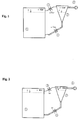
- Die Erfindung wird im folgenden anhand einer Zeichnung erläutert. Dabei zeigen die Figuren den Ablauf des Verfahrens.
- Die Anlage besteht aus einem Anaerob-Reaktor 1 und einem Faulschlammanreicherungsreaktor (FAR) 2 , die über einen Gasschieber 3 und einen Faulschlammschieber 4 miteinander verbunden sind. Beide Reaktoren 1, 2 sind gasdicht abgesclossen. Der FAR 2 ist mit einer Gaspumpe 5 versehen, die geeignet ist, einen Unterdruck in dem FAR zu bewirken.
- In Fig. 1 sind der Gasschieber 3 und der Faulschlammschieber 4 geöffnet, die Wasserspiegellagen in beiden Behältern (Ruhewasserspiegellagen y) gleichen sich aus; in den Gasphasen beider Reaktoren 1, 2 liegt der gleiche Druck von x mbar vor.
- Der sich zyklisch wiederholende Prozess beginnt damit, dass der Gasschieber 3 geschlossen wird und die Gasvakuumpumpe 5 im Gasraum des FAR 2 einen definierten Unterdruck x1 mbar erzeugt. Mit diesem Unterdruck korrespondiert ein neuer höherer Wasserspiegel y1 in dem FAR 2 durch die Zufuhr einer entsprechenden Faulschlammmenge aus dem Reaktor 1. Nachdem x1 mbar erricht ist, wird der Schieber 4 geschlossen (Fig 2) und der Unterdruck gegebenenfalls auf x2 mbar verstärkt. Danach wird der Unterdruck aufrechterhalten. Die Dauer des Unterdrucks kann je nach Ausfaulungsgrad einige Minuten bis mehrere Stunden andauern. Zweck dieser Unterdruckbehandlung ist, die Gaspartialdrücke (hierbei geht es nahezu ausschließlich um Kohlendioxid C02 und Methan CH4) des Faulschlammes in dem FAR 2 auf unter x mbar zu reduzieren.
- Danach wird der Gasschieber 3 geöffnet, so dass in der Gasphase des FAR 2 wieder ein Gasdruck von ungefähr x mbar entsteht. Da die Gaspartialdrücke in der Flüssigphase des FAR 2 deutlich unter x mbar liegen, wird, bis diese wieder auf Grund der fortlaufenden Faulprozesse auf x mbar ansteigen, ohne störenden Einfluss von aufsteigenden Gasblasen der Faulschlamm in dem FAR 2 sedimentieren und sich eine überstehende nahezu faulschlammfreie rein wässerige Zone 6 bilden (Fig. 3).
- Danach wird der Schlammschieber 4 geöffnet. Das Faulschlammkonzentrat 7 im unteren Bereich von des FAR 2 fließt in den Reaktor 1 bis sich beiden Wasserspiegellagen sich wieder auf y einstellen. Aus einem Ablauf 8 wird dann die nahezu faulschlammfreie Wasserfraktion entnommen und das Gesamtsystem kann mit dieser Menge an Rohsubstrat nachgespeist werden (Fig. 4). Danach kann ein neuer Anreicherungszyklus beginnen.
- Diese diskontinuierlichen Anreicherungszyklen verlaufen so lange bzw. so oft, bis der maximal möglich bzw. gewünschte TS-Gehalt in dem Reaktor 1 erreicht ist.
- Danach kann Netto-Überschussschlammproduktion an Faulschlamm mit den entnommenen Wasserfraktionen entnommen werden. Bevor dieser Zustand entsteht, kann optional über eine weitere Entnahmestelle 9 das Faulschlammkonzentrat entnommen werden.
- Die Vorteile dieser Prozessführung lassen sich wie folgt benennen:
- I) Es erfolgt eine sehr weitgehende Entkoppelung des partikulären Anteils des Faulschlamms von der Aufenthaltszeit des hydraulischen Anteils des zugeführten Abwassers/Schlammes. Durch diese Prozessführung kann die Aufenthaltszeit des Faulschlammes auf das gewünschte Schlammalter von z.B. 20 Tagen eingestellt werden, obwohl die Aufenthaltszeit des hydraulischen Anteils beispielsweise nur 5 Tage beträgt.
- II) Der Aufbau und Betrieb des Faulschlammanreicherungsreaktors (FAR) ist denkbar einfach. In diesem FAR befinden sich keinerlei Aggregate/Geräte oder bewegliche Teile, die eine Wartung erschweren würden. Der Automatikbetrieb beruht ausschließlich auf den externen automatischen Schiebern 3 und 4 und der Gaspumpe 5.
- III) Der FAR kann auch (Fig. 4) in einen Stufen- oder Parallelbetrieb integriert werden: Sowohl parallel betriebene Reaktoren als auch eine zweite Stufe können mit einem FAR verbunden und die Faulschlammanreicherung in jede beliebige Richtung geleitet werden.
Claims (3)
- Verfahren zur anaeroben Behandlung von Abwassern und Schlämmen in einem Faulreaktor, bei dem die Aufenthaltzeit der hydraulischen Bestandteile von der der partikulären Bestandteile entkoppelt ist,
gekennzeichnet durch diskontinuierliches Abführen eines Teiles des ausfaulenden Schlamms aus dem Faulreaktor,
Anreichern des abgeführten Teil des ausfaulenden Schlamms in einem Faulschlammanreicherungsreaktor und
Rückführen des angereicherten ausfaulenden Schlamms in den Faulreaktor. - Verfahren nach Anspruch 1, dadurch gekennzeichnet, dass das Abführen und Rückführen des ausfaulenden Schlamms über ein Einstellen des sich über dem Schlamm und des sich über diesem absetzenden hydraulischen Anteils befindlichen Gases herrschenden Drucks und des Öffnens und Schließens von den Faulbehälter mit dem Faulschlammanreicherungsreaktor verbindendenden Leitungen.
- Vorrichtung zur Durchführung des Verfahrens nach Anspruch 1 oder 2, gekennzeichnet durch einen Anaerob-Reaktor (1), einen mit diesem über eine mit einem Gasschieber (3) versehene Gasleitung und über eine mit einem Schlammschieber (4) versehene Schlammleitung verbundenen Faulschlammanreicherungsreaktor (2), der mit einer Gaspumpe (5) versehen ist.
Priority Applications (1)
| Application Number | Priority Date | Filing Date | Title |
|---|---|---|---|
| PL07001958T PL1820782T3 (pl) | 2006-02-10 | 2007-01-30 | Sposób obróbki ścieków |
Applications Claiming Priority (1)
| Application Number | Priority Date | Filing Date | Title |
|---|---|---|---|
| DE200610006166 DE102006006166B4 (de) | 2006-02-10 | 2006-02-10 | Verfahren und Anlage zur Behandlung von Schlämmen |
Publications (2)
| Publication Number | Publication Date |
|---|---|
| EP1820782A1 true EP1820782A1 (de) | 2007-08-22 |
| EP1820782B1 EP1820782B1 (de) | 2009-12-30 |
Family
ID=38015816
Family Applications (1)
| Application Number | Title | Priority Date | Filing Date |
|---|---|---|---|
| EP20070001958 Not-in-force EP1820782B1 (de) | 2006-02-10 | 2007-01-30 | Verfahren zur Behandlung von Schlämmen |
Country Status (5)
| Country | Link |
|---|---|
| EP (1) | EP1820782B1 (de) |
| AT (1) | ATE453606T1 (de) |
| DE (2) | DE102006006166B4 (de) |
| DK (1) | DK1820782T3 (de) |
| PL (1) | PL1820782T3 (de) |
Cited By (2)
| Publication number | Priority date | Publication date | Assignee | Title |
|---|---|---|---|---|
| EP2636651A1 (de) * | 2012-03-06 | 2013-09-11 | Lely Patent N.V. | System zum Verarbeiten von Biomasse |
| EP3974515A1 (de) * | 2020-09-28 | 2022-03-30 | ADG - Ateliers Des Graves | Doppelventilrohr für die ableitung des flüssigen anteils in einem biogaskreislauf |
Families Citing this family (1)
| Publication number | Priority date | Publication date | Assignee | Title |
|---|---|---|---|---|
| DE102007040622B4 (de) * | 2007-08-27 | 2017-02-09 | Hochschule Neubrandenburg - University of Applied Sciences | Vorrichtung und Verfahren zum Erzeugen von Biogas |
Citations (4)
| Publication number | Priority date | Publication date | Assignee | Title |
|---|---|---|---|---|
| US4632758A (en) * | 1985-09-06 | 1986-12-30 | Commonwealth Engineering & Technology, Inc. | Anaerobic wastewater treatment system |
| EP0737651A1 (de) * | 1993-12-28 | 1996-10-16 | Hitachi Zosen Corporation | Methode zum anaeroben abbau von klärschlamm |
| US5630942A (en) * | 1996-05-29 | 1997-05-20 | Purification Industries International | Two phase anaerobic digestion process utilizing thermophilic, fixed growth bacteria |
| US20030075501A1 (en) * | 2001-10-24 | 2003-04-24 | Wilkie Ann C. | Fixed-film anaerobic digestion of flushed manure |
Family Cites Families (2)
| Publication number | Priority date | Publication date | Assignee | Title |
|---|---|---|---|---|
| DE4042223A1 (de) * | 1990-12-29 | 1992-07-02 | Pwa Industriepapier Gmbh | Reaktor und verfahren zur kontinuierlichen mechanischen und anaerob biologischen reinigung feststoffhaltigen abwassers |
| DE102004003071B4 (de) * | 2004-01-21 | 2008-08-21 | Holm, Niels Christian, Dr. | Verfahren zur Abwasserreinigung |
-
2006
- 2006-02-10 DE DE200610006166 patent/DE102006006166B4/de not_active Expired - Fee Related
-
2007
- 2007-01-30 DE DE200750002448 patent/DE502007002448D1/de active Active
- 2007-01-30 DK DK07001958T patent/DK1820782T3/da active
- 2007-01-30 PL PL07001958T patent/PL1820782T3/pl unknown
- 2007-01-30 EP EP20070001958 patent/EP1820782B1/de not_active Not-in-force
- 2007-01-30 AT AT07001958T patent/ATE453606T1/de active
Patent Citations (4)
| Publication number | Priority date | Publication date | Assignee | Title |
|---|---|---|---|---|
| US4632758A (en) * | 1985-09-06 | 1986-12-30 | Commonwealth Engineering & Technology, Inc. | Anaerobic wastewater treatment system |
| EP0737651A1 (de) * | 1993-12-28 | 1996-10-16 | Hitachi Zosen Corporation | Methode zum anaeroben abbau von klärschlamm |
| US5630942A (en) * | 1996-05-29 | 1997-05-20 | Purification Industries International | Two phase anaerobic digestion process utilizing thermophilic, fixed growth bacteria |
| US20030075501A1 (en) * | 2001-10-24 | 2003-04-24 | Wilkie Ann C. | Fixed-film anaerobic digestion of flushed manure |
Cited By (3)
| Publication number | Priority date | Publication date | Assignee | Title |
|---|---|---|---|---|
| EP2636651A1 (de) * | 2012-03-06 | 2013-09-11 | Lely Patent N.V. | System zum Verarbeiten von Biomasse |
| EP3974515A1 (de) * | 2020-09-28 | 2022-03-30 | ADG - Ateliers Des Graves | Doppelventilrohr für die ableitung des flüssigen anteils in einem biogaskreislauf |
| FR3114632A1 (fr) * | 2020-09-28 | 2022-04-01 | Adg - Ateliers Des Graves | Conduit double vannes pour l’évacuation de la partie liquide présente dans un circuit de circulation de biogaz |
Also Published As
| Publication number | Publication date |
|---|---|
| EP1820782B1 (de) | 2009-12-30 |
| DK1820782T3 (da) | 2010-05-10 |
| DE502007002448D1 (de) | 2010-02-11 |
| DE102006006166B4 (de) | 2008-05-15 |
| DE102006006166A1 (de) | 2007-08-23 |
| ATE453606T1 (de) | 2010-01-15 |
| PL1820782T3 (pl) | 2010-06-30 |
Similar Documents
| Publication | Publication Date | Title |
|---|---|---|
| DE102010043630A1 (de) | Verfahren, Anlage und Methanreaktor zur Erhöhung der Methankonzentration des Biogases aus Biogasanlagen | |
| US11884565B2 (en) | Process for the production of bio-oil and biogas from biomass | |
| EP2707491A2 (de) | Verfahren zur herstellung von biogas aus überwiegend tierischen exkrementen | |
| DE19613397C2 (de) | Verfahren zum biologischen Reinigen von Abwasser | |
| DE102008032409A1 (de) | Verfahren zur Herstellung von Methan aus Prozeßwässern und biogenem Material | |
| DE102009009985A1 (de) | Verfahren zur Aufkonzentration von Mikroorganismen in wässrigen Substraten | |
| DE4409487A1 (de) | Verfahren und Anlage zur Vergärung von biogen-organischen Rohabfällen | |
| DE102014111287A1 (de) | Verfahren zur Erzeugung von Methan | |
| EP2982740A1 (de) | Verfahren zur erzeugung von methan | |
| EP1818314A2 (de) | Verfahren und Biogasanlage zur Herstellung von Biogas aus organisch beladenen Flüssigkeiten | |
| DE102013103704A1 (de) | Verfahren zur Optimierung der biologischen Nährstoffeliminierung aus Abwasser | |
| EP1820782B1 (de) | Verfahren zur Behandlung von Schlämmen | |
| López-Fernández et al. | Ultrafiltration as an advanced tertiary treatment of anaerobically digested swine manure liquid fraction: A practical and theoretical study | |
| DE102014111298A1 (de) | Verfahren zur Erzeugung von Methan | |
| DE102007004135A1 (de) | Verfahren und Vorrichtung zur Vergärung von Biomassen | |
| DE102010033442A1 (de) | Verfahren zur Aufkonzentration von Mikroorganismen in wässrigen Substraten | |
| EP3165598B1 (de) | Verfahren zum betreiben einer biogasanlage | |
| DE102014011479A1 (de) | Neues Verfahren zur Vergärung biogener Energieträger | |
| DE3534603A1 (de) | Verfahren zur weiterverarbeitung von aus einer biologischen abwasserreingiungsanlage abgezogenem rohschlamm | |
| DE102009008254A1 (de) | Verfahren zur Behandlung von bei Trockenvergärung anfallendem Perkolatwasser | |
| DE3534605A1 (de) | Verfahren zur weiterverarbeitung von aus einer biologischen abwasserreinigungsanlage abgezogenem rohschlamm | |
| EP3066205A1 (de) | Verfahren zur herstellung von biogas enthaltend eine verringerung der ammoniumkonzentration durch anammox | |
| US7445713B1 (en) | Method and facility for treating sludges | |
| DE19859665A1 (de) | Verfahren zur biologischen Behandlung hochnährstoffbelasteter Abwässer | |
| DE102017109733B4 (de) | Verfahren zum Betreiben einer Bioreaktoranlage |
Legal Events
| Date | Code | Title | Description |
|---|---|---|---|
| PUAI | Public reference made under article 153(3) epc to a published international application that has entered the european phase |
Free format text: ORIGINAL CODE: 0009012 |
|
| AK | Designated contracting states |
Kind code of ref document: A1 Designated state(s): AT BE BG CH CY CZ DE DK EE ES FI FR GB GR HU IE IS IT LI LT LU LV MC NL PL PT RO SE SI SK TR |
|
| AX | Request for extension of the european patent |
Extension state: AL BA HR MK YU |
|
| 17P | Request for examination filed |
Effective date: 20070809 |
|
| AKX | Designation fees paid |
Designated state(s): AT BE BG CH CY CZ DE DK EE ES FI FR GB GR HU IE IS IT LI LT LU LV MC NL PL PT RO SE SI SK TR |
|
| RTI1 | Title (correction) |
Free format text: PROCESS FOR THE TREATMENT OF SLUDGES |
|
| GRAP | Despatch of communication of intention to grant a patent |
Free format text: ORIGINAL CODE: EPIDOSNIGR1 |
|
| GRAS | Grant fee paid |
Free format text: ORIGINAL CODE: EPIDOSNIGR3 |
|
| GRAA | (expected) grant |
Free format text: ORIGINAL CODE: 0009210 |
|
| AK | Designated contracting states |
Kind code of ref document: B1 Designated state(s): AT BE BG CH CY CZ DE DK EE ES FI FR GB GR HU IE IS IT LI LT LU LV MC NL PL PT RO SE SI SK TR |
|
| REG | Reference to a national code |
Ref country code: GB Ref legal event code: FG4D Free format text: NOT ENGLISH |
|
| REG | Reference to a national code |
Ref country code: CH Ref legal event code: EP |
|
| REG | Reference to a national code |
Ref country code: CH Ref legal event code: NV Representative=s name: ISLER & PEDRAZZINI AG |
|
| REG | Reference to a national code |
Ref country code: IE Ref legal event code: FG4D |
|
| REF | Corresponds to: |
Ref document number: 502007002448 Country of ref document: DE Date of ref document: 20100211 Kind code of ref document: P |
|
| PG25 | Lapsed in a contracting state [announced via postgrant information from national office to epo] |
Ref country code: SE Free format text: LAPSE BECAUSE OF FAILURE TO SUBMIT A TRANSLATION OF THE DESCRIPTION OR TO PAY THE FEE WITHIN THE PRESCRIBED TIME-LIMIT Effective date: 20091230 Ref country code: LT Free format text: LAPSE BECAUSE OF FAILURE TO SUBMIT A TRANSLATION OF THE DESCRIPTION OR TO PAY THE FEE WITHIN THE PRESCRIBED TIME-LIMIT Effective date: 20091230 Ref country code: FI Free format text: LAPSE BECAUSE OF FAILURE TO SUBMIT A TRANSLATION OF THE DESCRIPTION OR TO PAY THE FEE WITHIN THE PRESCRIBED TIME-LIMIT Effective date: 20091230 |
|
| REG | Reference to a national code |
Ref country code: DK Ref legal event code: T3 |
|
| LTIE | Lt: invalidation of european patent or patent extension |
Effective date: 20091230 |
|
| PG25 | Lapsed in a contracting state [announced via postgrant information from national office to epo] |
Ref country code: SI Free format text: LAPSE BECAUSE OF FAILURE TO SUBMIT A TRANSLATION OF THE DESCRIPTION OR TO PAY THE FEE WITHIN THE PRESCRIBED TIME-LIMIT Effective date: 20091230 Ref country code: LV Free format text: LAPSE BECAUSE OF FAILURE TO SUBMIT A TRANSLATION OF THE DESCRIPTION OR TO PAY THE FEE WITHIN THE PRESCRIBED TIME-LIMIT Effective date: 20091230 |
|
| REG | Reference to a national code |
Ref country code: IE Ref legal event code: FD4D |
|
| PG25 | Lapsed in a contracting state [announced via postgrant information from national office to epo] |
Ref country code: BG Free format text: LAPSE BECAUSE OF FAILURE TO SUBMIT A TRANSLATION OF THE DESCRIPTION OR TO PAY THE FEE WITHIN THE PRESCRIBED TIME-LIMIT Effective date: 20100330 Ref country code: ES Free format text: LAPSE BECAUSE OF FAILURE TO SUBMIT A TRANSLATION OF THE DESCRIPTION OR TO PAY THE FEE WITHIN THE PRESCRIBED TIME-LIMIT Effective date: 20100410 Ref country code: EE Free format text: LAPSE BECAUSE OF FAILURE TO SUBMIT A TRANSLATION OF THE DESCRIPTION OR TO PAY THE FEE WITHIN THE PRESCRIBED TIME-LIMIT Effective date: 20091230 Ref country code: PT Free format text: LAPSE BECAUSE OF FAILURE TO SUBMIT A TRANSLATION OF THE DESCRIPTION OR TO PAY THE FEE WITHIN THE PRESCRIBED TIME-LIMIT Effective date: 20100430 Ref country code: IS Free format text: LAPSE BECAUSE OF FAILURE TO SUBMIT A TRANSLATION OF THE DESCRIPTION OR TO PAY THE FEE WITHIN THE PRESCRIBED TIME-LIMIT Effective date: 20100430 Ref country code: RO Free format text: LAPSE BECAUSE OF FAILURE TO SUBMIT A TRANSLATION OF THE DESCRIPTION OR TO PAY THE FEE WITHIN THE PRESCRIBED TIME-LIMIT Effective date: 20091230 |
|
| BERE | Be: lapsed |
Owner name: HOLM, NIELS CHRISTIAN Effective date: 20100131 |
|
| PG25 | Lapsed in a contracting state [announced via postgrant information from national office to epo] |
Ref country code: CZ Free format text: LAPSE BECAUSE OF FAILURE TO SUBMIT A TRANSLATION OF THE DESCRIPTION OR TO PAY THE FEE WITHIN THE PRESCRIBED TIME-LIMIT Effective date: 20091230 Ref country code: MC Free format text: LAPSE BECAUSE OF NON-PAYMENT OF DUE FEES Effective date: 20100131 Ref country code: SK Free format text: LAPSE BECAUSE OF FAILURE TO SUBMIT A TRANSLATION OF THE DESCRIPTION OR TO PAY THE FEE WITHIN THE PRESCRIBED TIME-LIMIT Effective date: 20091230 |
|
| PG25 | Lapsed in a contracting state [announced via postgrant information from national office to epo] |
Ref country code: GR Free format text: LAPSE BECAUSE OF FAILURE TO SUBMIT A TRANSLATION OF THE DESCRIPTION OR TO PAY THE FEE WITHIN THE PRESCRIBED TIME-LIMIT Effective date: 20100331 Ref country code: CY Free format text: LAPSE BECAUSE OF FAILURE TO SUBMIT A TRANSLATION OF THE DESCRIPTION OR TO PAY THE FEE WITHIN THE PRESCRIBED TIME-LIMIT Effective date: 20091230 Ref country code: IE Free format text: LAPSE BECAUSE OF FAILURE TO SUBMIT A TRANSLATION OF THE DESCRIPTION OR TO PAY THE FEE WITHIN THE PRESCRIBED TIME-LIMIT Effective date: 20091230 |
|
| PLBE | No opposition filed within time limit |
Free format text: ORIGINAL CODE: 0009261 |
|
| STAA | Information on the status of an ep patent application or granted ep patent |
Free format text: STATUS: NO OPPOSITION FILED WITHIN TIME LIMIT |
|
| 26N | No opposition filed |
Effective date: 20101001 |
|
| PG25 | Lapsed in a contracting state [announced via postgrant information from national office to epo] |
Ref country code: BE Free format text: LAPSE BECAUSE OF NON-PAYMENT OF DUE FEES Effective date: 20100131 |
|
| PG25 | Lapsed in a contracting state [announced via postgrant information from national office to epo] |
Ref country code: IT Free format text: LAPSE BECAUSE OF FAILURE TO SUBMIT A TRANSLATION OF THE DESCRIPTION OR TO PAY THE FEE WITHIN THE PRESCRIBED TIME-LIMIT Effective date: 20091230 |
|
| REG | Reference to a national code |
Ref country code: FR Ref legal event code: ST Effective date: 20110228 |
|
| PGFP | Annual fee paid to national office [announced via postgrant information from national office to epo] |
Ref country code: DK Payment date: 20110112 Year of fee payment: 5 |
|
| PG25 | Lapsed in a contracting state [announced via postgrant information from national office to epo] |
Ref country code: FR Free format text: LAPSE BECAUSE OF NON-PAYMENT OF DUE FEES Effective date: 20100301 |
|
| PGFP | Annual fee paid to national office [announced via postgrant information from national office to epo] |
Ref country code: NL Payment date: 20110117 Year of fee payment: 5 Ref country code: DE Payment date: 20110121 Year of fee payment: 5 Ref country code: CH Payment date: 20110124 Year of fee payment: 5 |
|
| PGFP | Annual fee paid to national office [announced via postgrant information from national office to epo] |
Ref country code: GB Payment date: 20110120 Year of fee payment: 5 |
|
| PGFP | Annual fee paid to national office [announced via postgrant information from national office to epo] |
Ref country code: PL Payment date: 20110131 Year of fee payment: 5 |
|
| REG | Reference to a national code |
Ref country code: NL Ref legal event code: V1 Effective date: 20120801 |
|
| REG | Reference to a national code |
Ref country code: CH Ref legal event code: PL |
|
| REG | Reference to a national code |
Ref country code: DK Ref legal event code: EBP |
|
| GBPC | Gb: european patent ceased through non-payment of renewal fee |
Effective date: 20120130 |
|
| PG25 | Lapsed in a contracting state [announced via postgrant information from national office to epo] |
Ref country code: HU Free format text: LAPSE BECAUSE OF FAILURE TO SUBMIT A TRANSLATION OF THE DESCRIPTION OR TO PAY THE FEE WITHIN THE PRESCRIBED TIME-LIMIT Effective date: 20100701 Ref country code: LU Free format text: LAPSE BECAUSE OF NON-PAYMENT OF DUE FEES Effective date: 20100130 |
|
| PG25 | Lapsed in a contracting state [announced via postgrant information from national office to epo] |
Ref country code: CH Free format text: LAPSE BECAUSE OF NON-PAYMENT OF DUE FEES Effective date: 20120131 Ref country code: TR Free format text: LAPSE BECAUSE OF FAILURE TO SUBMIT A TRANSLATION OF THE DESCRIPTION OR TO PAY THE FEE WITHIN THE PRESCRIBED TIME-LIMIT Effective date: 20091230 Ref country code: DE Free format text: LAPSE BECAUSE OF NON-PAYMENT OF DUE FEES Effective date: 20120801 Ref country code: GB Free format text: LAPSE BECAUSE OF NON-PAYMENT OF DUE FEES Effective date: 20120130 Ref country code: LI Free format text: LAPSE BECAUSE OF NON-PAYMENT OF DUE FEES Effective date: 20120131 |
|
| REG | Reference to a national code |
Ref country code: DE Ref legal event code: R119 Ref document number: 502007002448 Country of ref document: DE Effective date: 20120801 |
|
| PG25 | Lapsed in a contracting state [announced via postgrant information from national office to epo] |
Ref country code: DK Free format text: LAPSE BECAUSE OF NON-PAYMENT OF DUE FEES Effective date: 20120131 Ref country code: NL Free format text: LAPSE BECAUSE OF NON-PAYMENT OF DUE FEES Effective date: 20120801 |
|
| REG | Reference to a national code |
Ref country code: AT Ref legal event code: MM01 Ref document number: 453606 Country of ref document: AT Kind code of ref document: T Effective date: 20120130 |
|
| REG | Reference to a national code |
Ref country code: PL Ref legal event code: LAPE |
|
| PG25 | Lapsed in a contracting state [announced via postgrant information from national office to epo] |
Ref country code: PL Free format text: LAPSE BECAUSE OF NON-PAYMENT OF DUE FEES Effective date: 20120130 |
|
| PG25 | Lapsed in a contracting state [announced via postgrant information from national office to epo] |
Ref country code: AT Free format text: LAPSE BECAUSE OF NON-PAYMENT OF DUE FEES Effective date: 20120130 |