EP1820911A2 - Abflusseinrichtung - Google Patents
Abflusseinrichtung Download PDFInfo
- Publication number
- EP1820911A2 EP1820911A2 EP07102170A EP07102170A EP1820911A2 EP 1820911 A2 EP1820911 A2 EP 1820911A2 EP 07102170 A EP07102170 A EP 07102170A EP 07102170 A EP07102170 A EP 07102170A EP 1820911 A2 EP1820911 A2 EP 1820911A2
- Authority
- EP
- European Patent Office
- Prior art keywords
- drain
- layer
- drain installation
- aluminium
- steel
- Prior art date
- Legal status (The legal status is an assumption and is not a legal conclusion. Google has not performed a legal analysis and makes no representation as to the accuracy of the status listed.)
- Granted
Links
Images


Classifications
-
- B—PERFORMING OPERATIONS; TRANSPORTING
- B63—SHIPS OR OTHER WATERBORNE VESSELS; RELATED EQUIPMENT
- B63B—SHIPS OR OTHER WATERBORNE VESSELS; EQUIPMENT FOR SHIPPING
- B63B29/00—Accommodation for crew or passengers not otherwise provided for
- B63B29/16—Soil water discharges
-
- B—PERFORMING OPERATIONS; TRANSPORTING
- B32—LAYERED PRODUCTS
- B32B—LAYERED PRODUCTS, i.e. PRODUCTS BUILT-UP OF STRATA OF FLAT OR NON-FLAT, e.g. CELLULAR OR HONEYCOMB, FORM
- B32B15/00—Layered products comprising a layer of metal
- B32B15/01—Layered products comprising a layer of metal all layers being exclusively metallic
- B32B15/012—Layered products comprising a layer of metal all layers being exclusively metallic one layer being formed of an iron alloy or steel, another layer being formed of aluminium or an aluminium alloy
-
- E—FIXED CONSTRUCTIONS
- E03—WATER SUPPLY; SEWERAGE
- E03C—DOMESTIC PLUMBING INSTALLATIONS FOR FRESH WATER OR WASTE WATER; SINKS
- E03C1/00—Domestic plumbing installations for fresh water or waste water; Sinks
- E03C1/12—Plumbing installations for waste water; Basins or fountains connected thereto; Sinks
- E03C1/22—Outlet devices mounted in basins, baths, or sinks
Definitions
- the present invention concerns a drain installation for mounting in structures of aluminium and where the drain installations include steel, preferably stainless steel.
- the drain installation includes connecting means for disposition against the structure in which the drain installation is fitted, that these connecting means are made of a laminate at least including a layer of aluminium and a layer of steel which are united by rolling for forming the laminate in coherent form, and that the steel layer is welded to the drain installation while the aluminium layer is welded to the structure.
- the aluminium layer of the connecting means may now be welded to the aluminium parts of the structure and the steel layer of the connecting means to the steel parts of the drain installation.
- the drain installations hitherto used which have been of steel, usually stainless steel, may thus be mounted by welding in structures of aluminium. Welding of drain installations of steel is thus possible in structures as e.g. ships where floors, storey partitionings and other structural parts are made of aluminium.
- the drain installation according to the invention is peculiar in that the structure includes a navy vessel with deck and beam construction made of aluminium. Installations according to the invention are particularly suited for ships where hulls of aluminium are used to a higher degree, and where traditional drain installations in the form of drain bowls and drain pipes made of stainless steel are desired. According to a further embodiment according to the invention, the installation is peculiar in that it includes drain bowls and drain pipes.
- the drain installation according to the invention is peculiar in that the connecting means include a bushing with two concentric layers, or plane annular flanges with superposed layers, or a combination thereof.
- the connecting means may hereby be made in a simple way for interacting with drain bowls and drain pipes that necessitate fastening in surfaces via the annular flanges, or via beam structures or thicker structures via bushings.
- the drain installation according to the invention is peculiar in that the aluminium layer has a thickness between 3 and 8 mm, preferably 5-6 mm, and that the steel layer has a thickness between 3 and 8 mm, preferably 5-6 mm.
- This provides design advantages that satisfy by far the most situations of application. However, it is also possible to work with dimensions which are greater or lesser than these ranges.
- the drain installation according to the invention is peculiar in that the connecting means are separate elements which are connected to the drain installation in connection with its mounting in the structure.
- the installations may hereby be produced in a traditional way by using traditional tools and the connecting means are also made by methods and on tools for optimising the production process.
- optimise stores of elements for drain installations and connecting means This is particularly an advantage when not speaking of very standardised products, and where individual adaptation of the products is required.
- the drain installation according to the invention is peculiar in that the connecting means are separate elements which are connected to the drain installation in connection with its making. This enables making drain installations in a form in which they are ready for installation. This may particularly be an advantage by very standardised products.
- the drain installation according to the invention is peculiar in that the connecting means are elements made integral with the drain installation.
- the connecting means are elements made integral with the drain installation.
- the drain installation according to the invention is peculiar in that the aluminium , layer and the steel layer are united by rolling.
- this is a simple way of establishing a laminate which is brought together for forming the laminate in coherent form.
- a drain installation in the form of a drain pipe is generally designated with reference 1
- a drain installation in the form of a drain bowl will generally be designated with the reference 2.
- Drain pipes 1 and drain bowls 2 shown in the Figures are separate embodiments which are not exhaustive, as other forms of drain pipes and other forms of drain bowls are also possible within the scope of the invention.
- connecting means in the form of a flange is generally designated with reference 3, and connecting means in the form of a bushing will generally be designated with the reference 4. Furthermore, connecting means in the form of a collar bushing will generally be designated with the reference 5.
- flanges or bushings are only illustration of specific embodiments which are not exhaustive. Other embodiments of flanges and bushings will thus be possible within the scope of the invention.
- the connecting means 3-5 are made of a laminate which is generally designated with the reference 6.
- a laminate 6 appears, including two layers where an aluminium layer is generally designated with the reference 7, and a steel layer which is generally designated with the reference 8.
- the layers 7, 8 of the laminate 6 are in the same Figure provided in the form of a coherent laminate produced by rolling the two layers together.
- the laminate may consist of more layers, as it is only to be provided that an aluminium layer is provided for welding to a structure where the drain installation will be mounted, and a steel layer intended for being welded to the drain installation.
- the weldings 9, 10 may include large or small faces for the aluminium layer and the steel layer.
- Figs. 1 and 2 appears a drain pipe 1 which is provided with a flange 3. It is seen that the pipe 1 has an annular recess 11 for receiving a sealing ring 12.
- the annular flange 3 is provided with a steel layer 8 which has an aperture 13 with a diameter corresponding to the diameter of the pipe 1, and which is intended for resting on the top side of the recess 11.
- the aluminium layer 7 has an aperture 14 which is greater than the aperture 13 and intended for a position above the pipe 1.
- Fig. 4 shows a design where the steel layer 8 is disposed in the same way as shown in Fig. 3, and where the aluminium layer 7 is disposed at a position under the steel layer in order to be opposite the pipe 1.
- Fig. 5 shows a situation where the aperture 13, 14 has the same diameter in the aluminium layer 7 and the steel layer 8.
- the aluminium layer 7 is intended for being disposed above the steel layer, corresponding to the position shown in Fig. 3.
- Fig. 6 illustrates a situation where the apertures 13, 14 have the same diameter, as it is shown in Fig. 5. However, both layers 7, 8 are here disposed at a position under the recess 11.
- Figs. 7 and 8 show a pipe 1 with a bushing 4.
- the bushing 4 consists of two concentric rings, of which an inner ring is formed by a steel layer 8, and an outer layer is constituted by the aluminium layer 7.
- Fig. 10 is seen that the aluminium layer 7 is continued downwards in relation to the steel layer 8.
- Fig. 11 is seen that the aluminium layer 7 is continued upwards in relation to the steel layer 8.
- the bushing 4 is disposed at a position in the pipe 1 where this has a uniform cross-section.
- a bushing which is not circularly cylindric, and where the bushing thus can be placed at a position where the pipe has a bent part 15.
- Fig. 13 shows a pipe 1 which is provided with a collar bushing 5.
- an interspace 16 is provided within the bushing part of the collar bushing, as the annular steel layer 8 of the bushing is provided at its top side with an inwards directed annular flange 17 for contact with the pipe 1 at a position where the top side of the recess 11 on the pipe.
- Fig. 14 appears that the collar bushing has a bushing part consisting of two concentric overlaid layers.
- Fig. 15 is seen that the aluminium layer 7 of the bushing is displaced downwards in relation to the annular steel layer 8.
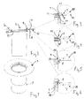
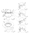
- Fig. 17 shows a drain bowl 2 with a flange 3. It appears that the drain bowl 2 has a drain stub 18 and an outer bowl 19 disposed thereabove. In the outer bowl 19, there may be provided inner bowls, return flow stop, gratings or other elements that may be required for the function of the drain bowl 2.
- the flange 13 may be disposed at other positions along the outer side of the outer bowl 19.
- Fig. 23 shows a drain bowl 2 corresponding to the drain bowls illustrated in Figs. 17 and 18.
- a bushing 4 is provided at a position around the outer bowl 19.
- Figs. 25-27 show different embodiments of the concentric layers 7, 8 of the bushing, corresponding to the embodiments explained with reference to Figs. 9-11.
- Figs. 25-27 is seen that the bushing 4 is provided with an upper edge provided with the upper aperture of the drain bowl 2. Alternatively, however, it will be possible to dispose the bushing at a position farther down at a straight section of the outer bowl 19 of the drain bowl. Mounting the bushing 4 at the outer side of the outer bowl 19 will hereby be largely identical to the mounting shown in connection with the pipe in Figs. 9-11.
- Fig. 28 shows a drain bowl 2 , now provided with a collar bushing 5.
- Fig. 29 is seen that the annular flange 17 of the collar bushing 5 is provided at the upper edge of the outer bowl 19.
- the drain bowl 2 corresponds to the drain bowl shown in Figs. 17, 18 and 23, 24.
- Figs. 30-32 appear various embodiments of the collar bushing by disposition on the outer bowl 19.
- the annular layers 7, 8 may be provided with the same configuration as illustrated in Figs. 14-16.
Landscapes
- Engineering & Computer Science (AREA)
- Life Sciences & Earth Sciences (AREA)
- Environmental & Geological Engineering (AREA)
- Hydrology & Water Resources (AREA)
- Water Supply & Treatment (AREA)
- Combustion & Propulsion (AREA)
- Mechanical Engineering (AREA)
- Ocean & Marine Engineering (AREA)
- Health & Medical Sciences (AREA)
- Public Health (AREA)
- Chemical & Material Sciences (AREA)
- Sink And Installation For Waste Water (AREA)
- Water Treatment By Sorption (AREA)
- Massaging Devices (AREA)
- Finger-Pressure Massage (AREA)
- Connection Of Plates (AREA)
- Sewage (AREA)
- Laminated Bodies (AREA)
- Flanged Joints, Insulating Joints, And Other Joints (AREA)
- Control And Other Processes For Unpacking Of Materials (AREA)
- Non-Silver Salt Photosensitive Materials And Non-Silver Salt Photography (AREA)
- Eye Examination Apparatus (AREA)
Applications Claiming Priority (1)
| Application Number | Priority Date | Filing Date | Title |
|---|---|---|---|
| DKPA200600220A DK176892B1 (da) | 2006-02-15 | 2006-02-15 | Afløbsinstallation |
Publications (3)
| Publication Number | Publication Date |
|---|---|
| EP1820911A2 true EP1820911A2 (de) | 2007-08-22 |
| EP1820911A3 EP1820911A3 (de) | 2008-06-04 |
| EP1820911B1 EP1820911B1 (de) | 2010-08-18 |
Family
ID=38121305
Family Applications (1)
| Application Number | Title | Priority Date | Filing Date |
|---|---|---|---|
| EP07102170A Active EP1820911B1 (de) | 2006-02-15 | 2007-02-12 | Abflusseinrichtung |
Country Status (6)
| Country | Link |
|---|---|
| EP (1) | EP1820911B1 (de) |
| AT (1) | ATE478204T1 (de) |
| DE (1) | DE602007008485D1 (de) |
| DK (2) | DK176892B1 (de) |
| ES (1) | ES2350261T3 (de) |
| NO (1) | NO336086B1 (de) |
Cited By (1)
| Publication number | Priority date | Publication date | Assignee | Title |
|---|---|---|---|---|
| AT523833B1 (de) * | 2020-09-08 | 2021-12-15 | Stefan Trautner | Rohrdurchführung durch ein Bauwerks-Trennelement |
Citations (3)
| Publication number | Priority date | Publication date | Assignee | Title |
|---|---|---|---|---|
| US3798010A (en) | 1968-07-30 | 1974-03-19 | Du Pont | Explosion bonded aluminum to steel |
| US4193529A (en) | 1977-01-24 | 1980-03-18 | The United States Of America As Represented By The Secretary Of The Navy | Method for interconnecting dissimilar metals welding to an explosively bonded bimetallic coupling |
| US20050012997A1 (en) | 2001-06-29 | 2005-01-20 | Canon Kabushiki Kaisha | Polarization beam splitter and method of producing the same |
Family Cites Families (4)
| Publication number | Priority date | Publication date | Assignee | Title |
|---|---|---|---|---|
| DE2242580C3 (de) * | 1972-08-30 | 1975-11-20 | Messer Griesheim Gmbh, 6000 Frankfurt | Rohrverbindungsstuck aus walzplattiertem Aluminium-Stahl-Verbundblech |
| JPS5412903B2 (de) * | 1974-04-15 | 1979-05-26 | ||
| US5296647A (en) * | 1991-10-25 | 1994-03-22 | Explosive Fabricators, Inc. | Assembly for connecting an electrical box to a plate with a bimetallic flange |
| US20050129971A1 (en) * | 2003-12-15 | 2005-06-16 | Ping Steven W. | Transition inserts and methods for joining dissimilar metals |
-
2006
- 2006-02-15 DK DKPA200600220A patent/DK176892B1/da not_active IP Right Cessation
-
2007
- 2007-02-12 DK DK07102170.3T patent/DK1820911T3/da active
- 2007-02-12 AT AT07102170T patent/ATE478204T1/de not_active IP Right Cessation
- 2007-02-12 DE DE602007008485T patent/DE602007008485D1/de active Active
- 2007-02-12 ES ES07102170T patent/ES2350261T3/es active Active
- 2007-02-12 EP EP07102170A patent/EP1820911B1/de active Active
- 2007-02-14 NO NO20070840A patent/NO336086B1/no unknown
Patent Citations (3)
| Publication number | Priority date | Publication date | Assignee | Title |
|---|---|---|---|---|
| US3798010A (en) | 1968-07-30 | 1974-03-19 | Du Pont | Explosion bonded aluminum to steel |
| US4193529A (en) | 1977-01-24 | 1980-03-18 | The United States Of America As Represented By The Secretary Of The Navy | Method for interconnecting dissimilar metals welding to an explosively bonded bimetallic coupling |
| US20050012997A1 (en) | 2001-06-29 | 2005-01-20 | Canon Kabushiki Kaisha | Polarization beam splitter and method of producing the same |
Cited By (2)
| Publication number | Priority date | Publication date | Assignee | Title |
|---|---|---|---|---|
| AT523833B1 (de) * | 2020-09-08 | 2021-12-15 | Stefan Trautner | Rohrdurchführung durch ein Bauwerks-Trennelement |
| AT523833A4 (de) * | 2020-09-08 | 2021-12-15 | Stefan Trautner | Rohrdurchführung durch ein Bauwerks-Trennelement |
Also Published As
| Publication number | Publication date |
|---|---|
| EP1820911A3 (de) | 2008-06-04 |
| NO20070840L (no) | 2007-08-16 |
| NO336086B1 (no) | 2015-05-11 |
| DK176892B1 (da) | 2010-03-08 |
| DE602007008485D1 (de) | 2010-09-30 |
| ES2350261T3 (es) | 2011-01-20 |
| EP1820911B1 (de) | 2010-08-18 |
| DK200600220A (da) | 2007-08-16 |
| DK1820911T3 (da) | 2010-12-13 |
| ATE478204T1 (de) | 2010-09-15 |
Similar Documents
| Publication | Publication Date | Title |
|---|---|---|
| JP2007192534A (ja) | 二重壁、放出式熱交換器 | |
| US8607508B2 (en) | Stayed connection for wind turbine | |
| EP1820911A2 (de) | Abflusseinrichtung | |
| JP5579943B1 (ja) | 配管用の補強用具 | |
| US20070080310A1 (en) | Electrolysis-resistant coupling assembly for valves | |
| EP3591143B1 (de) | Leistungsmast mit flansch, der mit rohrsegmenten verbunden ist | |
| KR101159793B1 (ko) | 복합 패널, 이를 포함하는 조립식 유체 저장탱크 및 , 이를 이용한 조립식 유체 저장탱크 시공방법 | |
| KR101717902B1 (ko) | 선박 기관실 데크 설치용 스쿠퍼와 그 제조방법 | |
| JP5529645B2 (ja) | 鋼製部材へのライニングプレートの固定構造 | |
| WO2002035141A1 (en) | Inter-locking grating | |
| JP2009002006A (ja) | 複合構造建物における柱の構造 | |
| CN110116783B (zh) | Lng加注船甲板的排水系统及膨胀伸缩接头制作方法 | |
| JP2006299750A (ja) | 水抜きボルト・ナット及びこれを使用した鋼箱の滞水防止用水抜き構造 | |
| KR20030085025A (ko) | 관 모양의 부품을 위한 연결 플랜지 | |
| JP7272823B2 (ja) | 梁補強構造及び梁補強方法 | |
| US3265354A (en) | Valve | |
| CN201779376U (zh) | 双金属复合异径接头 | |
| JP2009057745A (ja) | 異径鋼管柱の接合構造 | |
| US7062887B1 (en) | Intersecting structural member and a method for joining same | |
| JP5979907B2 (ja) | 継手構造及び継手方法 | |
| JP7382680B1 (ja) | 支柱部材と手摺部材との連結金具を生産する方法 | |
| JP2020204346A (ja) | 配管部材 | |
| JP2005264709A (ja) | 鉄骨構造物の柱梁接合部つばなし工法 | |
| JP2005009300A (ja) | 鋼管と鉄筋との接合構造および杭頭接合部 | |
| EP4520645A1 (de) | Schwimmende offshore-plattform mit miteinander verbundenen hohlen strukturelementen, stromerzeugungsanordnung mit solch einer plattform und zugehöriges herstellungsverfahren |
Legal Events
| Date | Code | Title | Description |
|---|---|---|---|
| PUAI | Public reference made under article 153(3) epc to a published international application that has entered the european phase |
Free format text: ORIGINAL CODE: 0009012 |
|
| AK | Designated contracting states |
Kind code of ref document: A2 Designated state(s): AT BE BG CH CY CZ DE DK EE ES FI FR GB GR HU IE IS IT LI LT LU LV MC NL PL PT RO SE SI SK TR |
|
| AX | Request for extension of the european patent |
Extension state: AL BA HR MK YU |
|
| PUAL | Search report despatched |
Free format text: ORIGINAL CODE: 0009013 |
|
| AK | Designated contracting states |
Kind code of ref document: A3 Designated state(s): AT BE BG CH CY CZ DE DK EE ES FI FR GB GR HU IE IS IT LI LT LU LV MC NL PL PT RO SE SI SK TR |
|
| AX | Request for extension of the european patent |
Extension state: AL BA HR MK RS |
|
| RIC1 | Information provided on ipc code assigned before grant |
Ipc: B63B 17/00 20060101ALI20080425BHEP Ipc: B32B 15/01 20060101ALI20080425BHEP Ipc: B63J 2/00 20060101ALI20080425BHEP Ipc: E03C 1/20 20060101AFI20070618BHEP Ipc: E03C 1/22 20060101ALI20080425BHEP Ipc: E03F 5/04 20060101ALI20080425BHEP |
|
| 17P | Request for examination filed |
Effective date: 20081204 |
|
| AKX | Designation fees paid |
Designated state(s): AT BE BG CH CY CZ DE DK EE ES FI FR GB GR HU IE IS IT LI LT LU LV MC NL PL PT RO SE SI SK TR |
|
| GRAP | Despatch of communication of intention to grant a patent |
Free format text: ORIGINAL CODE: EPIDOSNIGR1 |
|
| GRAS | Grant fee paid |
Free format text: ORIGINAL CODE: EPIDOSNIGR3 |
|
| GRAA | (expected) grant |
Free format text: ORIGINAL CODE: 0009210 |
|
| AK | Designated contracting states |
Kind code of ref document: B1 Designated state(s): AT BE BG CH CY CZ DE DK EE ES FI FR GB GR HU IE IS IT LI LT LU LV MC NL PL PT RO SE SI SK TR |
|
| REG | Reference to a national code |
Ref country code: GB Ref legal event code: FG4D |
|
| REG | Reference to a national code |
Ref country code: CH Ref legal event code: EP |
|
| REG | Reference to a national code |
Ref country code: IE Ref legal event code: FG4D |
|
| REF | Corresponds to: |
Ref document number: 602007008485 Country of ref document: DE Date of ref document: 20100930 Kind code of ref document: P |
|
| REG | Reference to a national code |
Ref country code: GR Ref legal event code: EP Ref document number: 20100402516 Country of ref document: GR |
|
| REG | Reference to a national code |
Ref country code: NL Ref legal event code: T3 |
|
| REG | Reference to a national code |
Ref country code: DK Ref legal event code: T3 |
|
| REG | Reference to a national code |
Ref country code: ES Ref legal event code: FG2A Effective date: 20110110 |
|
| LTIE | Lt: invalidation of european patent or patent extension |
Effective date: 20100818 |
|
| PG25 | Lapsed in a contracting state [announced via postgrant information from national office to epo] |
Ref country code: AT Free format text: LAPSE BECAUSE OF FAILURE TO SUBMIT A TRANSLATION OF THE DESCRIPTION OR TO PAY THE FEE WITHIN THE PRESCRIBED TIME-LIMIT Effective date: 20100818 Ref country code: LT Free format text: LAPSE BECAUSE OF FAILURE TO SUBMIT A TRANSLATION OF THE DESCRIPTION OR TO PAY THE FEE WITHIN THE PRESCRIBED TIME-LIMIT Effective date: 20100818 |
|
| PG25 | Lapsed in a contracting state [announced via postgrant information from national office to epo] |
Ref country code: PL Free format text: LAPSE BECAUSE OF FAILURE TO SUBMIT A TRANSLATION OF THE DESCRIPTION OR TO PAY THE FEE WITHIN THE PRESCRIBED TIME-LIMIT Effective date: 20100818 Ref country code: IS Free format text: LAPSE BECAUSE OF FAILURE TO SUBMIT A TRANSLATION OF THE DESCRIPTION OR TO PAY THE FEE WITHIN THE PRESCRIBED TIME-LIMIT Effective date: 20101218 Ref country code: BG Free format text: LAPSE BECAUSE OF FAILURE TO SUBMIT A TRANSLATION OF THE DESCRIPTION OR TO PAY THE FEE WITHIN THE PRESCRIBED TIME-LIMIT Effective date: 20101118 Ref country code: SI Free format text: LAPSE BECAUSE OF FAILURE TO SUBMIT A TRANSLATION OF THE DESCRIPTION OR TO PAY THE FEE WITHIN THE PRESCRIBED TIME-LIMIT Effective date: 20100818 Ref country code: PT Free format text: LAPSE BECAUSE OF FAILURE TO SUBMIT A TRANSLATION OF THE DESCRIPTION OR TO PAY THE FEE WITHIN THE PRESCRIBED TIME-LIMIT Effective date: 20101220 Ref country code: CY Free format text: LAPSE BECAUSE OF FAILURE TO SUBMIT A TRANSLATION OF THE DESCRIPTION OR TO PAY THE FEE WITHIN THE PRESCRIBED TIME-LIMIT Effective date: 20100818 |
|
| PG25 | Lapsed in a contracting state [announced via postgrant information from national office to epo] |
Ref country code: LV Free format text: LAPSE BECAUSE OF FAILURE TO SUBMIT A TRANSLATION OF THE DESCRIPTION OR TO PAY THE FEE WITHIN THE PRESCRIBED TIME-LIMIT Effective date: 20100818 Ref country code: BE Free format text: LAPSE BECAUSE OF FAILURE TO SUBMIT A TRANSLATION OF THE DESCRIPTION OR TO PAY THE FEE WITHIN THE PRESCRIBED TIME-LIMIT Effective date: 20100818 Ref country code: SE Free format text: LAPSE BECAUSE OF FAILURE TO SUBMIT A TRANSLATION OF THE DESCRIPTION OR TO PAY THE FEE WITHIN THE PRESCRIBED TIME-LIMIT Effective date: 20100818 |
|
| PG25 | Lapsed in a contracting state [announced via postgrant information from national office to epo] |
Ref country code: EE Free format text: LAPSE BECAUSE OF FAILURE TO SUBMIT A TRANSLATION OF THE DESCRIPTION OR TO PAY THE FEE WITHIN THE PRESCRIBED TIME-LIMIT Effective date: 20100818 Ref country code: SK Free format text: LAPSE BECAUSE OF FAILURE TO SUBMIT A TRANSLATION OF THE DESCRIPTION OR TO PAY THE FEE WITHIN THE PRESCRIBED TIME-LIMIT Effective date: 20100818 Ref country code: RO Free format text: LAPSE BECAUSE OF FAILURE TO SUBMIT A TRANSLATION OF THE DESCRIPTION OR TO PAY THE FEE WITHIN THE PRESCRIBED TIME-LIMIT Effective date: 20100818 |
|
| RIN2 | Information on inventor provided after grant (corrected) |
Inventor name: PFENNIG, VLADIMIR Inventor name: LOHMANN, HANS Inventor name: MUELLER, ALKEXANDER |
|
| PLBE | No opposition filed within time limit |
Free format text: ORIGINAL CODE: 0009261 |
|
| 26N | No opposition filed |
Effective date: 20110519 |
|
| REG | Reference to a national code |
Ref country code: DE Ref legal event code: R097 Ref document number: 602007008485 Country of ref document: DE Effective date: 20110519 |
|
| PG25 | Lapsed in a contracting state [announced via postgrant information from national office to epo] |
Ref country code: MC Free format text: LAPSE BECAUSE OF NON-PAYMENT OF DUE FEES Effective date: 20110228 |
|
| REG | Reference to a national code |
Ref country code: CH Ref legal event code: PL |
|
| PG25 | Lapsed in a contracting state [announced via postgrant information from national office to epo] |
Ref country code: LI Free format text: LAPSE BECAUSE OF NON-PAYMENT OF DUE FEES Effective date: 20110228 Ref country code: CH Free format text: LAPSE BECAUSE OF NON-PAYMENT OF DUE FEES Effective date: 20110228 |
|
| REG | Reference to a national code |
Ref country code: IE Ref legal event code: MM4A |
|
| PG25 | Lapsed in a contracting state [announced via postgrant information from national office to epo] |
Ref country code: IE Free format text: LAPSE BECAUSE OF NON-PAYMENT OF DUE FEES Effective date: 20110212 |
|
| PG25 | Lapsed in a contracting state [announced via postgrant information from national office to epo] |
Ref country code: LU Free format text: LAPSE BECAUSE OF NON-PAYMENT OF DUE FEES Effective date: 20110212 |
|
| PG25 | Lapsed in a contracting state [announced via postgrant information from national office to epo] |
Ref country code: TR Free format text: LAPSE BECAUSE OF FAILURE TO SUBMIT A TRANSLATION OF THE DESCRIPTION OR TO PAY THE FEE WITHIN THE PRESCRIBED TIME-LIMIT Effective date: 20100818 |
|
| PLAA | Information modified related to event that no opposition was filed |
Free format text: ORIGINAL CODE: 0009299DELT |
|
| PLBE | No opposition filed within time limit |
Free format text: ORIGINAL CODE: 0009261 |
|
| STAA | Information on the status of an ep patent application or granted ep patent |
Free format text: STATUS: NO OPPOSITION FILED WITHIN TIME LIMIT |
|
| PG25 | Lapsed in a contracting state [announced via postgrant information from national office to epo] |
Ref country code: HU Free format text: LAPSE BECAUSE OF FAILURE TO SUBMIT A TRANSLATION OF THE DESCRIPTION OR TO PAY THE FEE WITHIN THE PRESCRIBED TIME-LIMIT Effective date: 20100818 |
|
| R26N | No opposition filed (corrected) |
Effective date: 20110519 |
|
| RIN2 | Information on inventor provided after grant (corrected) |
Inventor name: PFENNIG, VLADIMIR Inventor name: MUELLER, ALEXANDER Inventor name: LOHMANN, HANS |
|
| REG | Reference to a national code |
Ref country code: FR Ref legal event code: RM Effective date: 20140213 |
|
| PGFP | Annual fee paid to national office [announced via postgrant information from national office to epo] |
Ref country code: ES Payment date: 20150226 Year of fee payment: 9 Ref country code: DK Payment date: 20150225 Year of fee payment: 9 |
|
| PGFP | Annual fee paid to national office [announced via postgrant information from national office to epo] |
Ref country code: GB Payment date: 20150226 Year of fee payment: 9 Ref country code: GR Payment date: 20150226 Year of fee payment: 9 |
|
| REG | Reference to a national code |
Ref country code: FR Ref legal event code: PLFP Year of fee payment: 10 |
|
| REG | Reference to a national code |
Ref country code: DK Ref legal event code: EBP Effective date: 20160229 |
|
| GBPC | Gb: european patent ceased through non-payment of renewal fee |
Effective date: 20160212 |
|
| PG25 | Lapsed in a contracting state [announced via postgrant information from national office to epo] |
Ref country code: GR Free format text: LAPSE BECAUSE OF NON-PAYMENT OF DUE FEES Effective date: 20160905 |
|
| PG25 | Lapsed in a contracting state [announced via postgrant information from national office to epo] |
Ref country code: DK Free format text: LAPSE BECAUSE OF NON-PAYMENT OF DUE FEES Effective date: 20160229 Ref country code: GB Free format text: LAPSE BECAUSE OF NON-PAYMENT OF DUE FEES Effective date: 20160212 |
|
| REG | Reference to a national code |
Ref country code: GR Ref legal event code: ML Ref document number: 20100402516 Country of ref document: GR Effective date: 20160905 |
|
| REG | Reference to a national code |
Ref country code: FR Ref legal event code: PLFP Year of fee payment: 11 |
|
| REG | Reference to a national code |
Ref country code: FR Ref legal event code: PLFP Year of fee payment: 12 |
|
| PG25 | Lapsed in a contracting state [announced via postgrant information from national office to epo] |
Ref country code: ES Free format text: LAPSE BECAUSE OF NON-PAYMENT OF DUE FEES Effective date: 20160213 |
|
| REG | Reference to a national code |
Ref country code: ES Ref legal event code: FD2A Effective date: 20181207 |
|
| P01 | Opt-out of the competence of the unified patent court (upc) registered |
Effective date: 20230516 |
|
| PGFP | Annual fee paid to national office [announced via postgrant information from national office to epo] |
Ref country code: NL Payment date: 20260226 Year of fee payment: 20 |
|
| PGFP | Annual fee paid to national office [announced via postgrant information from national office to epo] |
Ref country code: DE Payment date: 20260227 Year of fee payment: 20 |
|
| PGFP | Annual fee paid to national office [announced via postgrant information from national office to epo] |
Ref country code: FI Payment date: 20260225 Year of fee payment: 20 Ref country code: IT Payment date: 20260219 Year of fee payment: 20 |
|
| PGFP | Annual fee paid to national office [announced via postgrant information from national office to epo] |
Ref country code: FR Payment date: 20260225 Year of fee payment: 20 |
|
| PGFP | Annual fee paid to national office [announced via postgrant information from national office to epo] |
Ref country code: CZ Payment date: 20260127 Year of fee payment: 20 |