EP1820943B1 - Ensemble électrothermique chauffant pour l'antigivrage et le dégivrage d'un composant, composant de moteur à turbine à gaz et procédé de manufacture d'un ensemble chauffant associés - Google Patents
Ensemble électrothermique chauffant pour l'antigivrage et le dégivrage d'un composant, composant de moteur à turbine à gaz et procédé de manufacture d'un ensemble chauffant associés Download PDFInfo
- Publication number
- EP1820943B1 EP1820943B1 EP07250533.2A EP07250533A EP1820943B1 EP 1820943 B1 EP1820943 B1 EP 1820943B1 EP 07250533 A EP07250533 A EP 07250533A EP 1820943 B1 EP1820943 B1 EP 1820943B1
- Authority
- EP
- European Patent Office
- Prior art keywords
- heater assembly
- fabric layer
- resin
- fabric
- component
- Prior art date
- Legal status (The legal status is an assumption and is not a legal conclusion. Google has not performed a legal analysis and makes no representation as to the accuracy of the status listed.)
- Active
Links
Images

Classifications
-
- F—MECHANICAL ENGINEERING; LIGHTING; HEATING; WEAPONS; BLASTING
- F01—MACHINES OR ENGINES IN GENERAL; ENGINE PLANTS IN GENERAL; STEAM ENGINES
- F01D—NON-POSITIVE DISPLACEMENT MACHINES OR ENGINES, e.g. STEAM TURBINES
- F01D25/00—Component parts, details, or accessories, not provided for in, or of interest apart from, other groups
- F01D25/02—De-icing means for engines having icing phenomena
-
- F—MECHANICAL ENGINEERING; LIGHTING; HEATING; WEAPONS; BLASTING
- F01—MACHINES OR ENGINES IN GENERAL; ENGINE PLANTS IN GENERAL; STEAM ENGINES
- F01D—NON-POSITIVE DISPLACEMENT MACHINES OR ENGINES, e.g. STEAM TURBINES
- F01D5/00—Blades; Blade-carrying members; Heating, heat-insulating, cooling or antivibration means on the blades or the members
- F01D5/12—Blades
- F01D5/14—Form or construction
- F01D5/18—Hollow blades, i.e. blades with cooling or heating channels or cavities; Heating, heat-insulating or cooling means on blades
-
- F—MECHANICAL ENGINEERING; LIGHTING; HEATING; WEAPONS; BLASTING
- F02—COMBUSTION ENGINES; HOT-GAS OR COMBUSTION-PRODUCT ENGINE PLANTS
- F02C—GAS-TURBINE PLANTS; AIR INTAKES FOR JET-PROPULSION PLANTS; CONTROLLING FUEL SUPPLY IN AIR-BREATHING JET-PROPULSION PLANTS
- F02C7/00—Features, components parts, details or accessories, not provided for in, or of interest apart form groups F02C1/00 - F02C6/00; Air intakes for jet-propulsion plants
- F02C7/04—Air intakes for gas-turbine plants or jet-propulsion plants
- F02C7/047—Heating to prevent icing
-
- F—MECHANICAL ENGINEERING; LIGHTING; HEATING; WEAPONS; BLASTING
- F04—POSITIVE - DISPLACEMENT MACHINES FOR LIQUIDS; PUMPS FOR LIQUIDS OR ELASTIC FLUIDS
- F04D—NON-POSITIVE-DISPLACEMENT PUMPS
- F04D29/00—Details, component parts, or accessories
- F04D29/02—Selection of particular materials
- F04D29/023—Selection of particular materials especially adapted for elastic fluid pumps
-
- F—MECHANICAL ENGINEERING; LIGHTING; HEATING; WEAPONS; BLASTING
- F04—POSITIVE - DISPLACEMENT MACHINES FOR LIQUIDS; PUMPS FOR LIQUIDS OR ELASTIC FLUIDS
- F04D—NON-POSITIVE-DISPLACEMENT PUMPS
- F04D29/00—Details, component parts, or accessories
- F04D29/26—Rotors specially for elastic fluids
- F04D29/32—Rotors specially for elastic fluids for axial flow pumps
- F04D29/321—Rotors specially for elastic fluids for axial flow pumps for axial flow compressors
- F04D29/324—Blades
-
- F—MECHANICAL ENGINEERING; LIGHTING; HEATING; WEAPONS; BLASTING
- F04—POSITIVE - DISPLACEMENT MACHINES FOR LIQUIDS; PUMPS FOR LIQUIDS OR ELASTIC FLUIDS
- F04D—NON-POSITIVE-DISPLACEMENT PUMPS
- F04D29/00—Details, component parts, or accessories
- F04D29/58—Cooling; Heating; Diminishing heat transfer
- F04D29/582—Cooling; Heating; Diminishing heat transfer specially adapted for elastic fluid pumps
- F04D29/584—Cooling; Heating; Diminishing heat transfer specially adapted for elastic fluid pumps cooling or heating the machine
-
- F—MECHANICAL ENGINEERING; LIGHTING; HEATING; WEAPONS; BLASTING
- F04—POSITIVE - DISPLACEMENT MACHINES FOR LIQUIDS; PUMPS FOR LIQUIDS OR ELASTIC FLUIDS
- F04D—NON-POSITIVE-DISPLACEMENT PUMPS
- F04D29/00—Details, component parts, or accessories
- F04D29/58—Cooling; Heating; Diminishing heat transfer
- F04D29/582—Cooling; Heating; Diminishing heat transfer specially adapted for elastic fluid pumps
- F04D29/5853—Cooling; Heating; Diminishing heat transfer specially adapted for elastic fluid pumps heat insulation or conduction
-
- F—MECHANICAL ENGINEERING; LIGHTING; HEATING; WEAPONS; BLASTING
- F05—INDEXING SCHEMES RELATING TO ENGINES OR PUMPS IN VARIOUS SUBCLASSES OF CLASSES F01-F04
- F05D—INDEXING SCHEME FOR ASPECTS RELATING TO NON-POSITIVE-DISPLACEMENT MACHINES OR ENGINES, GAS-TURBINES OR JET-PROPULSION PLANTS
- F05D2300/00—Materials; Properties thereof
- F05D2300/40—Organic materials
- F05D2300/44—Resins
-
- F—MECHANICAL ENGINEERING; LIGHTING; HEATING; WEAPONS; BLASTING
- F05—INDEXING SCHEMES RELATING TO ENGINES OR PUMPS IN VARIOUS SUBCLASSES OF CLASSES F01-F04
- F05D—INDEXING SCHEME FOR ASPECTS RELATING TO NON-POSITIVE-DISPLACEMENT MACHINES OR ENGINES, GAS-TURBINES OR JET-PROPULSION PLANTS
- F05D2300/00—Materials; Properties thereof
- F05D2300/60—Properties or characteristics given to material by treatment or manufacturing
- F05D2300/601—Fabrics
-
- F—MECHANICAL ENGINEERING; LIGHTING; HEATING; WEAPONS; BLASTING
- F05—INDEXING SCHEMES RELATING TO ENGINES OR PUMPS IN VARIOUS SUBCLASSES OF CLASSES F01-F04
- F05D—INDEXING SCHEME FOR ASPECTS RELATING TO NON-POSITIVE-DISPLACEMENT MACHINES OR ENGINES, GAS-TURBINES OR JET-PROPULSION PLANTS
- F05D2300/00—Materials; Properties thereof
- F05D2300/60—Properties or characteristics given to material by treatment or manufacturing
- F05D2300/603—Composites; e.g. fibre-reinforced
-
- F—MECHANICAL ENGINEERING; LIGHTING; HEATING; WEAPONS; BLASTING
- F05—INDEXING SCHEMES RELATING TO ENGINES OR PUMPS IN VARIOUS SUBCLASSES OF CLASSES F01-F04
- F05D—INDEXING SCHEME FOR ASPECTS RELATING TO NON-POSITIVE-DISPLACEMENT MACHINES OR ENGINES, GAS-TURBINES OR JET-PROPULSION PLANTS
- F05D2300/00—Materials; Properties thereof
- F05D2300/60—Properties or characteristics given to material by treatment or manufacturing
- F05D2300/614—Fibres or filaments
-
- Y—GENERAL TAGGING OF NEW TECHNOLOGICAL DEVELOPMENTS; GENERAL TAGGING OF CROSS-SECTIONAL TECHNOLOGIES SPANNING OVER SEVERAL SECTIONS OF THE IPC; TECHNICAL SUBJECTS COVERED BY FORMER USPC CROSS-REFERENCE ART COLLECTIONS [XRACs] AND DIGESTS
- Y02—TECHNOLOGIES OR APPLICATIONS FOR MITIGATION OR ADAPTATION AGAINST CLIMATE CHANGE
- Y02T—CLIMATE CHANGE MITIGATION TECHNOLOGIES RELATED TO TRANSPORTATION
- Y02T50/00—Aeronautics or air transport
- Y02T50/60—Efficient propulsion technologies, e.g. for aircraft
Definitions
- the present invention relates to a heater assembly. More particularly, the present invention relates to an electrothermal heater assembly that is suitable for removing and/or preventing ice accumulation on a gas turbine engine component.
- the heating element may also be applied to a surface of the component.
- the heating element heats the susceptible areas of the component in order to help prevent ice from forming.
- the heating element may be a metallic heating element (e.g., a foil element) formed of stainless steel, copper, wire cloth, etc., which typically converts electrical energy into heat energy.
- the metallic heating element is typically a part of a heater assembly that also includes a thermally conductive fabric layer attached to and supporting the heating element.
- the heater assembly may be formed of a metallic heating element embedded into an epoxy fiberreinforced composite structure.
- the fabric layer also electrically insulates an electrically conductive component from the heating element.
- multiple plies of fabric are required for sufficient electrical isolation of the metallic heater element.
- the heater assembly When the heater assembly is embedded in a composite structure of some gas turbine engine components, the heater assembly replaces some structural elements of the composite in order to maintain the dimensions of the component. In those cases, the heating element accounts for a percentage of the composite structure that forms the component. This may affect the strength and the structural characteristics, such as the transfer of structural loads, of the component. The larger the percentage the heater assembly constitutes, the larger the reduction in composite strength of the gas turbine engine component.
- the present invention relates to heater assemblies suitable for deicing and/or anti-icing a gas turbine engine component.
- a heater assembly as claimed in claim 1.
- a gas turbine engine as claimed in claim 9.
- a method of forming a heater assembly as claimed in claim 15. The method may comprise positioning a second fabric layer adjacent to the heating element (14;24;34) prior to injecting the resin into the first fabric layer, the second fabric layer being substantially similar to the first fabric layer, wherein the heating element is positioned between the first and second fabric layers.
- the present invention is an electrothermal heater assembly that includes a metallic heating element and a densely woven fabric layer impregnated with a high temperature resin that is capable of withstanding operating temperatures of up to 288°C (550°F).
- the resin reinforces the fabric layer.
- the metallic heating element is attached to the fabric layer using a thermoset adhesive and is electrically connected to a source of electrical power using any suitable conductor, such as a wire or flexible circuit.
- the resin that is introduced into the fabric layer is also the thermoset adhesive that adheres the metallic heating element to the fabric layer.
- the heater assembly of the present invention is suitable for incorporating (or embedding) into a composite structure of a component (i.e., an internal application), including a gas turbine engine component, or for attaching to a surface of a component (i.e., an external application) in order to deice the component and/or prevent ice from forming thereon.
- the heater assembly may also be used in a hybrid configuration, which includes both internal and external applications.
- the component may be any component that is susceptible to ice formation.
- the component may be an aircraft component or a gas turbine engine component such as, but not limited to, a vane, an airfoil leading edge, a front bearing of the engine, a structural strut that supports the front bearing, and a duct.
- the component may be formed of materials such as, but not limited to, fiberglass, metal, or carbon composite.
- FIG. 1A is a schematic cross-sectional view of electrothermal heater assembly 10 in accordance with the present invention.
- Heater assembly 10 includes densely woven fabric layer 12 and metallic heating elements 14, which are attached to densely woven fabric layer 12 with thermoset adhesive 16.
- Fabric layer 12 is impregnated with a high-temperature resin that is capable of withstanding temperatures of up to 288 °C (550 °F).
- suitable high-temperature resins include, but are not limited to, bismaleimide, phthalonitrile, cyanate ester, polyimide adhesive, and polyimide resin.
- Fabric layer 12 includes about 45 to about 70 percent by volume of a fabric and about 30 to about 55 percent by volume of the high-temperature resin. In one embodiment, fabric layer 12 includes about 55 to about 60 percent by volume of the fabric and about 40 to about 45 percent by volume of the high-temperature resin.
- Suitable fabrics for including in fabric layer 12 include densely woven materials that have a continuous fiber. Preferably, the fabric is not easily distorted and maintains its weave pattern prior to and during the introduction of resin into the fabric during manufacture of heater assembly 10.
- Suitable densely woven materials include a fiberglass fabric, such as Style 106, which is made commercially available by Clark Schwebel Tech-Fab Company of Anderson, South Carolina, and a polymer film, such as Kapton, which is made commercially available by DuPont High Performance Materials of Circleville, Ohio.
- Fabric layer 12 acts as a backing material to support heating elements 14, and in some embodiments, also acts as a structural element of a component (if heater assembly 10 is embedded in the component). Because fabric layer 12 supports heating elements 14, it may also be referred to as a "structural layer.” Some heating elements 14 require a backing material because they are thin and fragile and, as a result, cannot be easily handled during the manufacturing process. For example, heater assembly 10 may be etched into a shape prior to application in or on a component. The shape typically depends upon the type of component and the area of the component that requires deicing and/or anti-icing. Some of these fragile heating elements 14 tend to break apart during the etching process without a backing material (i.e., fabric layer 12). Fabric layer 12 contributes to the mechanical integrity of heating elements 14.
- fabric layer 12 of the present invention is load bearing and more stiff, due to the type of the fabric that is selected for including in fabric layer 12.
- fabric layer 12 contributes to the structural integrity of the component and can act as a structural element of the component, rather than merely taking up space in the component that could be occupied by a structural element.
- the fabric material included in fabric layer 12 may also constitute all or substantially all of the structural material in a composite component, such as a vane.
- fabric layer 12 is also electrically insulating and configured to electrically insulate an electrically conductive component, such as one formed of a carbon composite or a metal alloy, from metallic heating elements 14, while at the same time, thermally conduct heat generated by heating elements 14.
- an electrically conductive component such as one formed of a carbon composite or a metal alloy
- metallic heating elements 14 it is desirable for the fabric material forming fabric layer 12 to be woven tightly enough to be electrically insulating.
- Electrically insulating materials that may be used to form fabric layer 12 include fiberglass, Nextel or another suitable ceramic fiber fabric.
- heater assembly 10 A thickness of heater assembly 10 is minimized because fabric layer 12 is thinner than many existing heating assemblies, which include structural layers that are about 0.0508 centimeters (0.020 inches) thick.
- heater assembly 10 of the present invention includes fabric layer 12 that is less than about 0.0127 centimeters (0.005 inches) thick.
- fabric layer 12 is about 0.00762 centimeters (0.003 inches) to about 0.0127 centimeters (0.005 inches) thick. Given the increased structural integrity of fabric layer 12, and in some embodiments, its ability to electrically insulate heating elements 14, it has been found that only one layer of material is typically required to form fabric layer 12. Of course, fabric layer 12 may also be formed of multiple layers of material.
- fabric layer 12 is also an electrically insulating layer, the thickness of fabric layer 12 varies depending on the voltage feeding heating elements 14.
- healer assembly 10 is embedded in a component, the amount of structural material of the component that is displaced by heater assembly 10 is reduced because the thickness of heater assembly 10 is reduced.
- fabric layer 12 is also load bearing, and in some embodiments, is a suitable structural substitution for structural elements of the component. As a result, the component is more structurally sound than a similar component that incorporates an existing heater assembly. Reducing a thickness of fabric layer 12 of heater assembly 10 helps reduce the weight of heater assembly 10, which may be desirable in the case of gas turbine engine components, which are used in aircrafts.
- Thermal conductivity of fabric layer 12 contributes to the even distribution of heat that is generated by heating elements 14.
- the fabric layer 12 exhibits a thermal conductivity value of 1.45 W/m-K (10.1 BTU-in/br-ft 2 -°F).
- the heating assemblies include thick heating elements in order to achieve the necessary operating temperatures through the thick fabric layers. It has been found that is difficult to incorporate these heating assemblies into a component having a small radius (e.g., less than about 1.27 centimeters (0.50 inches)) because the thick heating elements fracture upon bending around a radius of less than about 1.27 centimeters (0.50 inches). Heater assembly 10 in accordance with the present invention, however, is more flexible than many of these existing heating assemblies due to the thinner fabric layer 12.
- heater assembly 10 can be used with components having a small radius while retaining the full capability of heater assembly 10.
- Metallic heating elements 14 are resistive heating elements, such as titanium, stainless steel, copper or wire cloth heating elements, which convert electrically energy into thermal heat, as is known in the art.
- FIG. 1A illustrates four heating elements 14, heater assembly 10 may include any number of heating elements 14, and those skilled in the art can modify the number of heating elements depending upon the specific application of heater assembly 10.
- Heating elements 14 are each electrically connected to an electrical power source using any suitable conductor, such as a wire or a flexible circuit.
- Various power arrangements may be used to provide power to heating elements 14 of heater assembly 10.
- heating elements 14 may be electrically connected to one another, or each of the heating elements 14 may be separately electrically connected to the power source.
- the electrical energy may be intermittently or continuously supplied to heating elements 14, depending upon whether a deicing or anti-icing function is desired. Typically, in the case of a deicing function, power is intermittently supplied to heating elements 14, whereas in an anti-icing function, power is continuously supplied to heating elements 14.
- Metallic heating elements 14 each include a watt density in a range of about 0.155 watts/cm 2 (1 watt/in 2 ) to about 7.75 watts/cm 2 /in 2 (50 watts).
- the watt density varies depending on the particular application of heater assembly 10.
- the watt density varies between heating elements 14.
- heater assembly 10 includes at least two heating elements 14 having different watt densities. The zone heating may require a secondary power distribution system in order to vary the power distribution between heating elements 14.
- Metallic heating elements 14 are capable of operating at temperatures of up to 288 °C (550 °F) due to the high-temperature resin that impregnates fabric layer 12.
- Many existing heating assemblies include a structural layer impregnated with a resin, such as epoxy, that is unable to withstand temperatures greater than 148.89 °C (300 °F). In those cases, the integrity of the fabric layer is compromised and the heating elements may become detached from the fabric layer if the heater assembly operates at temperatures greater than 148.89 °C (300 °F) and if the heater assembly is exposed to temperatures greater than 148.89 °C (300 °F).
- the high-temperature resin in heater assembly 10 is able to withstand temperatures of up to 288 °C (550°F), thereby helping to maintain the integrity of heater assembly 10 at temperatures greater than 288 °C (550 °F).
- heater assembly 10 may be used in because heater assembly 10 may be used to deice/anti-ice gas turbine engine components that operate at temperatures greater than 148.89 °C (300 °F). Many existing heating assemblies that use resin that cannot withstand temperatures greater than about 148.89 °C (300 °F) will fail and be unable to deice and anti-ice components that operate at higher operating temperatures (i.e., the temperatures between 148.89 °C (300 °F) and up to 288 °C (550 °F).
- thermoset adhesive 16 is applied to a ply of high-density material that forms fabric layer 12. Heating elements 14 are then positioned on the layer of thermoset adhesive 16 and positioned with respect to one another as desired. High-temperature resin is then injected into the material, thereby impregnating the material with the resin and forming fabric layer 12. The resin and thermoset adhesive are then cured, and as a result, heating elements 14 are adhered to fabric layer 12 after the curing step. The resulting heater assembly 10 may then be etched into a shape suitable for the specific application of heater assembly 10.
- FIG. 1B is a schematic cross-sectional view of electrothermal heater assembly 20 in accordance with a second embodiment of the present invention.
- Heater assembly 20 includes densely woven fabric layer 22, which is impregnated with a high-temperature resin, and metallic heating elements 24, which are adhered to fabric layer 22 with the high-temperature resin.
- Fabric layer 22 is similar to fabric layer 12 of heater assembly 10 of FIG. 1
- heating elements 24 are similar to heating elements 14 of heater assembly 10.
- the high-temperature resin that impregnates fabric layer 22 also adheres metallic heating elements 24 to fabric layer 22.
- heating elements 24 may be positioned next to a ply of material that forms fabric layer 22.
- a high-temperature resin is then injected into the ply of material and the resin is cured (thereby forming fabric layer 22).
- resin is present along surface 22A of fabric layer 22, on which heating elements 24 are positioned. Therefore, after the resin on surface 22A is cured, the cured resin along surface 22A acts as an adhesive to adhere heating elements 24 to fabric layer 22.
- FIG. 1C is a schematic cross-sectional view of electrothermal heater assembly 30 in accordance with a third embodiment of the present invention.
- Heater assembly includes fabric layers 32 and 36 and heating elements 34, which are adhered to fabric layers 32 and 36 with a high-temperature resin.
- Fabric layers 32 and 36 are similar to fabric layers 12 and 22 of FIGS. 1A and 1B , respectively, and heating elements 34 are similar to heating elements 14 and 24 of FIGS. 1A and 1B , respectively.
- Heater assembly 30 is similar to heater assembly 20 of FIG. 1B , except that second fabric layer 36 is adhered to heating elements 34. If fabric layers 32 and 36 are electrically insulative and heater assembly 30 is embedded into or attached to an external surface of electrically conductive component, fabric layers 32 and 36 electrically insulate the electrically conductive component from heating elements 34.
- a method similar to the method discussed above in reference to heater assembly 20 may be used to form heater assembly 30.
- a second ply of material is positioned adjacent to heating elements 34 so that heating elements 34 are "sandwiched" between the plies of material.
- the high-temperature resin is then injected into the plies of material and the resin is cured.
- the cured resin adheres heating elements 24 to fabric layer 36.
- the first embodiment of heater assembly 10 may also be modified to include a second fabric layer to electrically insulate heating elements 14. However, because a separate thermoset adhesive 16 is used in heater assembly 10, a second layer of thermoset adhesive is used to adhere heating elements 14 to the second fabric layer.
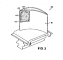
- FIG. 2 illustrates an embodiment of a composite component that includes a heater assembly.
- FIG. 2 is a perspective view of airfoil 40, where a portion of body 41 of airfoil 40 has been cutaway along leading edge 42 to expose heater assembly 44.
- Body 41 of airfoil 40 is a composite structure, and heater assembly 44 is embedded in body 41 as part of the composite.
- Heater assembly 44 is similar to heater assembly 10 of FIG. 1A , and includes fabric layer 46 embedded with a high-temperature resin and heating elements 48 (in phantom), which are attached to fabric layer 46 using a thermoset adhesive. As shown, fabric layer 46 is positioned between the exterior surface of body 41 and heating elements 48.
- other configurations are also contemplated.
- Airfoil 40 is a gas turbine engine component, and may be, for example, an airfoil in a compressor. If the gas turbine engine is used in an aircraft, moisture may accumulate on leading edge 42 of airfoil 40, and as the aircraft reaches higher elevations and the atmospheric temperature decreases, the moisture may turn into ice. In order to prevent the accumulation of ice (i.e., anti-ice) along leading edge 42 of airfoil 40, or remove the ice (i.e., deice) therefrom, heater assembly 44 is embedded in leading edge 42. As heating elements 48 receive electrical energy from an external power source (not shown), heating elements 48 convert the electrical power into thermal energy, thereby heating leading edge 42 of airfoil 40. Leading edge 42 of airfoil 40 is heated sufficiently enough to melt any accumulated ice and/or prevent ice from forming on leading edge 42.
- ice i.e., anti-ice
- heater assembly 44 is embedded in leading edge 42. As heating elements 48 receive electrical energy from an external power source (not shown), heating elements 48
Landscapes
- Engineering & Computer Science (AREA)
- Mechanical Engineering (AREA)
- General Engineering & Computer Science (AREA)
- Chemical & Material Sciences (AREA)
- Combustion & Propulsion (AREA)
- Physics & Mathematics (AREA)
- Thermal Sciences (AREA)
- Surface Heating Bodies (AREA)
- Resistance Heating (AREA)
- Structures Of Non-Positive Displacement Pumps (AREA)
Claims (17)
- Ensemble de chauffage électrothermique (10) destiné à l'antigivrage et au dégivrage d'un composant, l'ensemble de chauffage électrothermique comprenant :un élément métallique de chauffage (14 ; 24 ; 34) ; etune couche de tissu (12 ; 22 ; 32) adjacente à l'élément métallique de chauffage (14 ; 24 ; 34) et imprégnée d'une résine par injection, dans lequel la couche de tissu (12 ; 22 ; 32) contient un matériau de type tissu choisi dans un ensemble constitué d'un tissu en fibre de verre, d'un film en polymère et de leurs combinaisons ; caractérisé en ce queladite résine est à même de supporter une température de fonctionnement d'ensemble chauffant pouvant atteindre 550 °F (288 °C) ;ladite couche de tissu (12 ; 22 ; 32) a une valeur de conductivité thermique proche de 1,45 W/m.K(10,1 BTU-po/h-pied2-°F) ; etle matériau de tissu représente environ 45 à environ 70 % en volume de la couche de tissu (12 ; 22 ; 32).
- Ensemble de chauffage selon la revendication 1, dans lequel la résine est choisie dans un groupe constitué de : bismaléimide, phtalonitrile, cyanate ester, adhésif à base de polyimide et résine de polyimide.
- Ensemble de chauffage selon la revendication 1 ou 2, dans lequel la couche de tissu (12 ; 22 ; 32) isole électriquement le composant de l'élément métallique de chauffage (14 ; 24 ; 34).
- Ensemble de chauffage selon l'une quelconque des revendications précédentes, dans lequel la couche de tissu (12 ; 22 ; 32) représente moins d'environ 0,0127 cm (0,005 pouce) d'épaisseur.
- Ensemble de chauffage selon l'une quelconque des revendications précédentes, dans lequel l'élément métallique de chauffage (14 ; 24 ; 34) est un élément de chauffage à base de titane.
- Ensemble de chauffage selon l'une quelconque des revendications précédentes, dans lequel l'élément métallique de chauffage (14 ; 24 ; 34) a une densité de puissance comprise entre environ 0,155 W/cm2 (1 W/po2) et environ 7,75 W/cm2 (50 W/po2).
- Ensemble de chauffage selon l'une quelconque des revendications précédentes, dans lequel l'élément métallique de chauffage (14) est collé à la couche de tissu (12) à l'aide d'un adhésif (16) choisi dans un groupe constitué de la résine et d'un adhésif thermodurcissable.
- Ensemble de chauffage selon l'une quelconque des revendications précédentes, dans lequel l'élément métallique de chauffage (14 ; 24 ; 34) a une épaisseur d'environ 0,0127 à 0,1016 cm (0,5 à environ 40 millièmes de pouce).
- Composant de moteur de turbine à gaz (40) comprenant :un corps (41) ; etun ensemble de chauffage électrothermique (44) selon la revendication 1.
- Composant de moteur de turbine à gaz selon la revendication 9, dans lequel la résine est choisie dans un ensemble constitué de : bismaléimide, de phtalonitrile, de cyanate ester, d'adhésif au polyimide et de résine au polyimide.
- Composant de moteur de turbine à gaz selon la revendication 9 ou 10, dans lequel la couche de tissu (12 ; 22 ; 32) représente moins d'environ 0,0127 cm (0,005 pouce) d'épaisseur.
- Composant de moteur de turbine à gaz selon l'une quelconque des revendications 9 à 11, dans lequel le corps (41) est électroconducteur et où la couche de tissu (12 ; 22 ; 32) isole électriquement le composant de moteur de turbine à gaz (40) de l'élément métallique de chauffage (14 ; 24 ; 34).
- Composant de moteur de turbine à gaz selon l'une quelconque des revendications 9 à 12, dans lequel l'ensemble de chauffage (44) est logé dans le corps (41).
- Composant de moteur de turbine à gaz selon l'une quelconque des revendications 9 à 12, dans lequel l'ensemble de chauffage (44) est attaché à une surface extérieure du corps (41).
- Procédé de formation d'un ensemble de chauffage (10), ce procédé comprenant :l'utilisation d'une couche de tissu comprenant un matériau de type tissu choisi dans un ensemble constitué d'un tissu de fibre de verre, d'un tissu de fibre de céramique, d'un film de polymère et de leurs combinaisons, le matériau de type tissu représentant d'environ 45 à environ 70 % en volume de la couche de tissu (12 ; 22 ; 32) et la couche de tissu présentant une valeur de conductivité thermique d'environ 1,45 W/m.K (10,1 BTU-po/h-pied2-°F) ;le positionnement d'un élément métallique de chauffage (14 ; 24 ; 34) à côté de ladite couche de tissu ; et l'injection d'une résine dans la couche de tissu pour l'imprégner, la résine étant à même de supporter une température de fonctionnement pouvant atteindre 288 °C (550 °F).
- Procédé selon la revendication 15, dans lequel la résine est choisie dans un ensemble constitué de bismaléimide, de phtalonitrile, de cyanate ester, d'adhésif à base de polyimide et de résine à base de polyimide.
- Procédé selon la revendication 15 ou 16, dans lequel la couche de tissu a une épaisseur inférieure à environ 0,0127 cm (0,005 pouce).
Applications Claiming Priority (1)
| Application Number | Priority Date | Filing Date | Title |
|---|---|---|---|
| US11/356,329 US20070187381A1 (en) | 2006-02-16 | 2006-02-16 | Heater assembly for deicing and/or anti-icing a component |
Publications (3)
| Publication Number | Publication Date |
|---|---|
| EP1820943A2 EP1820943A2 (fr) | 2007-08-22 |
| EP1820943A3 EP1820943A3 (fr) | 2010-09-01 |
| EP1820943B1 true EP1820943B1 (fr) | 2015-08-26 |
Family
ID=37997731
Family Applications (1)
| Application Number | Title | Priority Date | Filing Date |
|---|---|---|---|
| EP07250533.2A Active EP1820943B1 (fr) | 2006-02-16 | 2007-02-09 | Ensemble électrothermique chauffant pour l'antigivrage et le dégivrage d'un composant, composant de moteur à turbine à gaz et procédé de manufacture d'un ensemble chauffant associés |
Country Status (3)
| Country | Link |
|---|---|
| US (2) | US20070187381A1 (fr) |
| EP (1) | EP1820943B1 (fr) |
| JP (1) | JP2007231942A (fr) |
Families Citing this family (52)
| Publication number | Priority date | Publication date | Assignee | Title |
|---|---|---|---|---|
| US20070267545A1 (en) * | 2005-04-18 | 2007-11-22 | Orr James R | Asset protection method and apparatus |
| US20060231683A1 (en) * | 2005-04-18 | 2006-10-19 | Orr James R | Aircraft & motor vehicle protection system that eliminates eleven safety and environmental hazards associated with aircraft and vehicles parked or tied down and exposed to the elements and animals |
| US9133714B2 (en) | 2006-11-01 | 2015-09-15 | United Technologies Corporation | Titanium foil as a structural heater element |
| US9581033B2 (en) * | 2007-02-06 | 2017-02-28 | United Technologies Corp0Ration | Surface mounted flexible heater for gas turbine engine application |
| US8049147B2 (en) | 2008-03-28 | 2011-11-01 | United Technologies Corporation | Engine inlet ice protection system with power control by zone |
| US8006934B2 (en) * | 2008-03-31 | 2011-08-30 | United Technologies Corporation | Heating architecture for a composite fairing |
| US7938368B2 (en) | 2008-04-07 | 2011-05-10 | United Technologies Corporation | Nosecone ice protection system for a gas turbine engine |
| FR2930234B1 (fr) * | 2008-04-21 | 2010-07-30 | Aircelle Sa | Systeme de degivrage et/ou d'antigivrage pour bord d'attaque de voilure d'aeronef. |
| EP2113635A1 (fr) * | 2008-04-30 | 2009-11-04 | Siemens Aktiengesellschaft | Turbine à vapeur à condensation à plusieurs étages |
| US20100024612A1 (en) | 2008-07-30 | 2010-02-04 | United Technologies Corporation | Installation tool for use with u-shaped component |
| FR2934566B1 (fr) * | 2008-08-04 | 2011-03-11 | Aircelle Sa | Procede de fabrication d'un ensemble de degivrage sur un panneau d'une nacelle. |
| US9656757B2 (en) * | 2008-09-16 | 2017-05-23 | Hamilton Sundstrand Corporation | Propeller deicing system |
| US20100108661A1 (en) * | 2008-10-31 | 2010-05-06 | United Technologies Corporation | Multi-layer heating assembly and method |
| US8246291B2 (en) * | 2009-05-21 | 2012-08-21 | Rolls-Royce Corporation | Thermal system for a working member of a power plant |
| GB0914502D0 (en) * | 2009-08-19 | 2009-09-30 | Rolls Royce Plc | Electrical conductor paths |
| US8342908B2 (en) * | 2009-08-31 | 2013-01-01 | United Technologies Corporation | Thermal mechanical skive for composite machining |
| US8431869B2 (en) | 2010-06-02 | 2013-04-30 | GM Global Technology Operations LLC | Defrosting, defogging and de-icing structures |
| US8844258B2 (en) | 2011-11-23 | 2014-09-30 | General Electric Company | Systems and methods for de-icing a gas turbine engine inlet screen and dehumidifying inlet air filters |
| US20130193127A1 (en) * | 2012-01-26 | 2013-08-01 | General Electric Company | Combustion turbine inlet anti-icing resistive heating system |
| US20130251500A1 (en) * | 2012-03-23 | 2013-09-26 | Kin-Leung Cheung | Gas turbine engine case with heating layer and method |
| US9359898B2 (en) * | 2012-04-19 | 2016-06-07 | General Electric Company | Systems for heating rotor disks in a turbomachine |
| US20140014776A1 (en) * | 2012-07-13 | 2014-01-16 | Kelly Aerospace Thermal Systems Llc | System containing an electric heating element and method for installation and use thereof |
| EP2943657B1 (fr) | 2013-01-14 | 2019-08-14 | United Technologies Corporation | Aube de guidage d'entrée structurale composite matriciel organique pour moteur à turbine |
| WO2014137418A2 (fr) | 2013-03-07 | 2014-09-12 | Rolls-Royce Corporation | Récupérateur de véhicule |
| US9845699B2 (en) * | 2013-03-15 | 2017-12-19 | Gkn Aerospace Services Structures Corp. | Fan spacer having unitary over molded feature |
| FR3003720B1 (fr) * | 2013-03-21 | 2017-12-01 | Tresse Metallique J Forissier | Element conducteur pour la realisation d'un systeme chauffant |
| EP2816200B1 (fr) * | 2013-06-18 | 2017-02-01 | General Electric Technology GmbH | Procédé et dispositif permettant de supprimer la formation de glace sur les structures au niveau de l'admission d'air d'une turbomachine |
| EP3044429B1 (fr) * | 2013-09-12 | 2021-06-30 | Raytheon Technologies Corporation | Procédé de fabrication de segments de panneau de glace |
| US9868536B2 (en) * | 2013-10-30 | 2018-01-16 | Goodrich Corporation | Electrical interconnects for ice protection systems |
| US20170238367A1 (en) * | 2016-02-15 | 2017-08-17 | General Electric Company | Integrated Conductive Foam Core for Composite Processing |
| CN106650081B (zh) * | 2016-12-19 | 2019-08-27 | 北京航空航天大学 | 冲击-热气膜复合式防冰结构设计方法 |
| US10494107B2 (en) * | 2017-01-03 | 2019-12-03 | Goodrich Corporation | Additive manufacturing of conformal deicing and boundary layer control surface for aircraft |
| CN106811714B (zh) * | 2017-03-31 | 2019-07-23 | 武汉理工大学 | 一种高电阻率电热涂层及其制备方法和应用 |
| KR102060191B1 (ko) | 2017-05-22 | 2019-12-27 | 주식회사 엘지화학 | 브레이크 패드 마찰재용 수지 조성물 및 상기 수지 조성물로 제조된 브레이크 패드 마찰재 |
| JP7223386B2 (ja) * | 2017-12-15 | 2023-02-16 | 国立研究開発法人宇宙航空研究開発機構 | ファンブレード及びエンジン |
| US10815885B2 (en) * | 2018-07-26 | 2020-10-27 | Raytheon Technologies Corporation | Anti-ice systems for engine airfoils |
| US11242151B2 (en) * | 2018-10-16 | 2022-02-08 | Goodrich Corporation | Method of using printed highly flexible conductive ink bus bars to transfer power to heated components |
| JP7339869B2 (ja) * | 2019-12-04 | 2023-09-06 | 東日本旅客鉄道株式会社 | 鉄道車両の台車カバー |
| US11655768B2 (en) | 2021-07-26 | 2023-05-23 | General Electric Company | High fan up speed engine |
| US11739689B2 (en) | 2021-08-23 | 2023-08-29 | General Electric Company | Ice reduction mechanism for turbofan engine |
| US11767790B2 (en) | 2021-08-23 | 2023-09-26 | General Electric Company | Object direction mechanism for turbofan engine |
| US11480063B1 (en) | 2021-09-27 | 2022-10-25 | General Electric Company | Gas turbine engine with inlet pre-swirl features |
| US12116929B2 (en) | 2022-01-19 | 2024-10-15 | General Electric Company | Bleed flow assembly for a gas turbine engine |
| US11788465B2 (en) | 2022-01-19 | 2023-10-17 | General Electric Company | Bleed flow assembly for a gas turbine engine |
| US12509993B1 (en) * | 2022-01-21 | 2025-12-30 | Rtx Corporation | Composite airfoil with integrated anti-icing for an aircraft propulsion system |
| US20230265862A1 (en) | 2022-02-21 | 2023-08-24 | General Electric Company | Turbofan engine having angled inlet pre-swirl vanes |
| US11808281B2 (en) | 2022-03-04 | 2023-11-07 | General Electric Company | Gas turbine engine with variable pitch inlet pre-swirl features |
| US11725526B1 (en) | 2022-03-08 | 2023-08-15 | General Electric Company | Turbofan engine having nacelle with non-annular inlet |
| US12209557B1 (en) | 2023-11-30 | 2025-01-28 | General Electric Company | Gas turbine engine with forward swept outlet guide vanes |
| US12385430B2 (en) | 2023-11-30 | 2025-08-12 | General Electric Company | Gas turbine engine with forward swept outlet guide vanes |
| US12228037B1 (en) | 2023-12-04 | 2025-02-18 | General Electric Company | Guide vane assembly with fixed and variable pitch inlet guide vanes |
| US12313021B1 (en) | 2024-03-14 | 2025-05-27 | General Electric Company | Outer nacelle with inlet guide vanes and acoustic treatment |
Family Cites Families (15)
| Publication number | Priority date | Publication date | Assignee | Title |
|---|---|---|---|---|
| US2992317A (en) | 1957-10-14 | 1961-07-11 | Goodrich Co B F | Electrically heated ice-removal apparatus |
| US3509568A (en) | 1968-07-08 | 1970-04-28 | North American Rockwell | Inlet attenuator assembly |
| GB2105520A (en) * | 1981-06-04 | 1983-03-23 | Rolls Royce | Electro-mechanical aircraft de-icer |
| FR2590681B1 (fr) * | 1985-11-27 | 1988-06-24 | Alcatel Espace | Systeme de localisation d'un objet muni d'au moins une mire passive. |
| US5925375A (en) * | 1987-05-22 | 1999-07-20 | The Liposome Company, Inc. | Therapeutic use of multilamellar liposomal prostaglandin formulations |
| ATE104493T1 (de) * | 1990-01-24 | 1994-04-15 | Hastings Otis | Elektrisch leitendes laminat fuer temperaturregelung von oberflaechen. |
| FR2686761B1 (fr) * | 1992-01-24 | 1994-05-27 | Seb Sa | Element chauffant a structure sandwich et appareil electromenager du type fer a repasser a vapeur comportant un tel element. |
| CA2176359C (fr) | 1993-11-30 | 2004-01-27 | David Charles Lawson | Dispositif de chauffage composite electriquement conducteur et procede de fabrication de ce dispositif |
| FR2731237B1 (fr) * | 1995-03-02 | 1997-04-30 | Seb Sa | Structure chauffante, notamment pour appareil electromenager realise selon une structure sandwich et appareil electromenager comportant une telle structure chauffante |
| US5657951A (en) * | 1995-06-23 | 1997-08-19 | The B.F. Goodrich Company | Electrothermal de-icing system |
| FR2756254B1 (fr) * | 1996-11-27 | 1999-01-29 | Eurocopter France | Dispositif de chauffage d'un profil aerodynamique |
| ES2209142T3 (es) * | 1997-05-20 | 2004-06-16 | Thermion Systems International | Dispositivo y metodo para calentar y descongelar alabes de turbina de energia eolica. |
| US6402093B1 (en) * | 2000-07-13 | 2002-06-11 | Lockheed Martin Corporation | Method and apparatus for autonomous de-icing |
| US6725645B1 (en) | 2002-10-03 | 2004-04-27 | General Electric Company | Turbofan engine internal anti-ice device |
| US7246773B2 (en) * | 2004-05-06 | 2007-07-24 | Goodrich Coporation | Low power, pulsed, electro-thermal ice protection system |
-
2006
- 2006-02-16 US US11/356,329 patent/US20070187381A1/en not_active Abandoned
-
2007
- 2007-02-09 EP EP07250533.2A patent/EP1820943B1/fr active Active
- 2007-02-15 JP JP2007034307A patent/JP2007231942A/ja active Pending
- 2007-07-05 US US11/825,174 patent/US7789620B2/en active Active
Also Published As
| Publication number | Publication date |
|---|---|
| US20070187381A1 (en) | 2007-08-16 |
| EP1820943A3 (fr) | 2010-09-01 |
| JP2007231942A (ja) | 2007-09-13 |
| US20080124222A1 (en) | 2008-05-29 |
| EP1820943A2 (fr) | 2007-08-22 |
| US7789620B2 (en) | 2010-09-07 |
Similar Documents
| Publication | Publication Date | Title |
|---|---|---|
| US7789620B2 (en) | Heater assembly for deicing and/or anti-icing a component | |
| US5925275A (en) | Electrically conductive composite heater and method of manufacture | |
| EP0732038B1 (fr) | Dispositif de chauffage composite electriquement conducteur et procede de fabrication de ce dispositif | |
| JP5933919B2 (ja) | ターボ機械ナセル及び氷結防止システム並びにその方法 | |
| US9193466B2 (en) | Aircraft ice protection system and method | |
| US9771866B2 (en) | High temperature composite inlet | |
| EP2204247B1 (fr) | Moules avec chauffage intégré et leurs procédés de fabrication | |
| US11338933B2 (en) | Acoustic honeycomb panel with integrated electrical heater | |
| JP2010511534A (ja) | 熱により影響を与えることができる材料から成る構成部材に一次成形形状付与または二次成形形状付与するための成形工具 | |
| US11618574B2 (en) | Heatable leading-edge apparatus, leading-edge heating system and aircraft comprising them | |
| US20100108661A1 (en) | Multi-layer heating assembly and method | |
| EP2390182B1 (fr) | Système de chauffage d'avion | |
| CN112124556A (zh) | 一种多功能蒙皮结构及其制备方法 | |
| US20190357312A1 (en) | Structural component for an aircraft | |
| EP3407678B1 (fr) | Procédé de fabrication de feuilles de nanotube carbone complexes | |
| JP2008115458A (ja) | 薄チタンフォイルを表面処理する方法およびこれを用いたアセンブリ | |
| US8630534B2 (en) | Heating system and component with such a heating system | |
| CN106321372A (zh) | 适用于风力发电机叶片防冰/融冰的复合碳纤维发热元件 | |
| US11591959B2 (en) | Generator air gap heater | |
| WO2025031648A1 (fr) | Pale d'éolienne intégrant un système de protection contre la glace et son procédé de fabrication | |
| KR102474962B1 (ko) | 방제빙용 복합재 구조물과 그 제조 시스템 및 제조 방법 | |
| JPH04336235A (ja) | 繊維補強熱可塑性樹脂パイプ | |
| CN121928827A (zh) | 一种复合材料结构碳基高导电复合膜及其制备方法 | |
| EP1116412A1 (fr) | Composants pour haut-parleurs comprenant des composites de carbone a structure d'inclinaison | |
| JPH0676926A (ja) | 面状発熱体 |
Legal Events
| Date | Code | Title | Description |
|---|---|---|---|
| PUAI | Public reference made under article 153(3) epc to a published international application that has entered the european phase |
Free format text: ORIGINAL CODE: 0009012 |
|
| AK | Designated contracting states |
Kind code of ref document: A2 Designated state(s): AT BE BG CH CY CZ DE DK EE ES FI FR GB GR HU IE IS IT LI LT LU LV MC NL PL PT RO SE SI SK TR |
|
| AX | Request for extension of the european patent |
Extension state: AL BA HR MK YU |
|
| PUAL | Search report despatched |
Free format text: ORIGINAL CODE: 0009013 |
|
| AK | Designated contracting states |
Kind code of ref document: A3 Designated state(s): AT BE BG CH CY CZ DE DK EE ES FI FR GB GR HU IE IS IT LI LT LU LV MC NL PL PT RO SE SI SK TR |
|
| AX | Request for extension of the european patent |
Extension state: AL BA HR MK RS |
|
| 17P | Request for examination filed |
Effective date: 20110301 |
|
| AKX | Designation fees paid |
Designated state(s): DE GB |
|
| 17Q | First examination report despatched |
Effective date: 20110901 |
|
| GRAP | Despatch of communication of intention to grant a patent |
Free format text: ORIGINAL CODE: EPIDOSNIGR1 |
|
| INTG | Intention to grant announced |
Effective date: 20150123 |
|
| GRAP | Despatch of communication of intention to grant a patent |
Free format text: ORIGINAL CODE: EPIDOSNIGR1 |
|
| INTG | Intention to grant announced |
Effective date: 20150617 |
|
| GRAS | Grant fee paid |
Free format text: ORIGINAL CODE: EPIDOSNIGR3 |
|
| GRAA | (expected) grant |
Free format text: ORIGINAL CODE: 0009210 |
|
| AK | Designated contracting states |
Kind code of ref document: B1 Designated state(s): DE GB |
|
| REG | Reference to a national code |
Ref country code: GB Ref legal event code: FG4D |
|
| REG | Reference to a national code |
Ref country code: DE Ref legal event code: R081 Ref document number: 602007042757 Country of ref document: DE Owner name: UNITED TECHNOLOGIES CORP. (N.D.GES.D. STAATES , US Free format text: FORMER OWNER: UNITED TECHNOLOGIES INC., HARTFORD, CONN., US |
|
| REG | Reference to a national code |
Ref country code: DE Ref legal event code: R096 Ref document number: 602007042757 Country of ref document: DE |
|
| REG | Reference to a national code |
Ref country code: DE Ref legal event code: R097 Ref document number: 602007042757 Country of ref document: DE |
|
| PLBE | No opposition filed within time limit |
Free format text: ORIGINAL CODE: 0009261 |
|
| STAA | Information on the status of an ep patent application or granted ep patent |
Free format text: STATUS: NO OPPOSITION FILED WITHIN TIME LIMIT |
|
| 26N | No opposition filed |
Effective date: 20160530 |
|
| REG | Reference to a national code |
Ref country code: DE Ref legal event code: R082 Ref document number: 602007042757 Country of ref document: DE Representative=s name: SCHMITT-NILSON SCHRAUD WAIBEL WOHLFROM PATENTA, DE |
|
| REG | Reference to a national code |
Ref country code: DE Ref legal event code: R082 Ref document number: 602007042757 Country of ref document: DE Representative=s name: SCHMITT-NILSON SCHRAUD WAIBEL WOHLFROM PATENTA, DE Ref country code: DE Ref legal event code: R081 Ref document number: 602007042757 Country of ref document: DE Owner name: UNITED TECHNOLOGIES CORP. (N.D.GES.D. STAATES , US Free format text: FORMER OWNER: UNITED TECHNOLOGIES CORP., HARTFORD, CONN., US |
|
| REG | Reference to a national code |
Ref country code: DE Ref legal event code: R081 Ref document number: 602007042757 Country of ref document: DE Owner name: RAYTHEON TECHNOLOGIES CORPORATION (N.D.GES.D.S, US Free format text: FORMER OWNER: UNITED TECHNOLOGIES CORP. (N.D.GES.D. STAATES DELAWARE), FARMINGTON, CONN., US Ref country code: DE Ref legal event code: R081 Ref document number: 602007042757 Country of ref document: DE Owner name: RTX CORPORATION (N.D.GES.D. STAATES DELAWARE),, US Free format text: FORMER OWNER: UNITED TECHNOLOGIES CORP. (N.D.GES.D. STAATES DELAWARE), FARMINGTON, CONN., US |
|
| P01 | Opt-out of the competence of the unified patent court (upc) registered |
Effective date: 20230519 |
|
| PGFP | Annual fee paid to national office [announced via postgrant information from national office to epo] |
Ref country code: DE Payment date: 20250122 Year of fee payment: 19 |
|
| PGFP | Annual fee paid to national office [announced via postgrant information from national office to epo] |
Ref country code: GB Payment date: 20250124 Year of fee payment: 19 |
|
| REG | Reference to a national code |
Ref country code: DE Ref legal event code: R081 Ref document number: 602007042757 Country of ref document: DE Owner name: RTX CORPORATION (N.D.GES.D. STAATES DELAWARE),, US Free format text: FORMER OWNER: RAYTHEON TECHNOLOGIES CORPORATION (N.D.GES.D.STAATES DELAWARE), ARLINGTON, VA, US |