EP1820947A2 - Brennkraftmaschine - Google Patents
Brennkraftmaschine Download PDFInfo
- Publication number
- EP1820947A2 EP1820947A2 EP07250121A EP07250121A EP1820947A2 EP 1820947 A2 EP1820947 A2 EP 1820947A2 EP 07250121 A EP07250121 A EP 07250121A EP 07250121 A EP07250121 A EP 07250121A EP 1820947 A2 EP1820947 A2 EP 1820947A2
- Authority
- EP
- European Patent Office
- Prior art keywords
- passage
- engine
- cooling water
- crank case
- water
- Prior art date
- Legal status (The legal status is an assumption and is not a legal conclusion. Google has not performed a legal analysis and makes no representation as to the accuracy of the status listed.)
- Withdrawn
Links
- XLYOFNOQVPJJNP-UHFFFAOYSA-N water Substances O XLYOFNOQVPJJNP-UHFFFAOYSA-N 0.000 claims abstract description 102
- 239000000498 cooling water Substances 0.000 claims abstract description 91
- 238000004891 communication Methods 0.000 claims description 20
- 239000012530 fluid Substances 0.000 claims description 18
- 238000005192 partition Methods 0.000 description 14
- 238000001816 cooling Methods 0.000 description 8
- 238000004519 manufacturing process Methods 0.000 description 6
- 238000005266 casting Methods 0.000 description 3
- 238000005516 engineering process Methods 0.000 description 1
- 238000012986 modification Methods 0.000 description 1
- 230000004048 modification Effects 0.000 description 1
- 238000005549 size reduction Methods 0.000 description 1
Images




Classifications
-
- F—MECHANICAL ENGINEERING; LIGHTING; HEATING; WEAPONS; BLASTING
- F01—MACHINES OR ENGINES IN GENERAL; ENGINE PLANTS IN GENERAL; STEAM ENGINES
- F01P—COOLING OF MACHINES OR ENGINES IN GENERAL; COOLING OF INTERNAL-COMBUSTION ENGINES
- F01P5/00—Pumping cooling-air or liquid coolants
- F01P5/10—Pumping liquid coolant; Arrangements of coolant pumps
-
- F—MECHANICAL ENGINEERING; LIGHTING; HEATING; WEAPONS; BLASTING
- F01—MACHINES OR ENGINES IN GENERAL; ENGINE PLANTS IN GENERAL; STEAM ENGINES
- F01M—LUBRICATING OF MACHINES OR ENGINES IN GENERAL; LUBRICATING INTERNAL COMBUSTION ENGINES; CRANKCASE VENTILATING
- F01M1/00—Pressure lubrication
- F01M1/02—Pressure lubrication using lubricating pumps
-
- F—MECHANICAL ENGINEERING; LIGHTING; HEATING; WEAPONS; BLASTING
- F01—MACHINES OR ENGINES IN GENERAL; ENGINE PLANTS IN GENERAL; STEAM ENGINES
- F01P—COOLING OF MACHINES OR ENGINES IN GENERAL; COOLING OF INTERNAL-COMBUSTION ENGINES
- F01P11/00—Component parts, details, or accessories not provided for in, or of interest apart from, groups F01P1/00 - F01P9/00
- F01P11/04—Arrangements of liquid pipes or hoses
-
- F—MECHANICAL ENGINEERING; LIGHTING; HEATING; WEAPONS; BLASTING
- F01—MACHINES OR ENGINES IN GENERAL; ENGINE PLANTS IN GENERAL; STEAM ENGINES
- F01P—COOLING OF MACHINES OR ENGINES IN GENERAL; COOLING OF INTERNAL-COMBUSTION ENGINES
- F01P2050/00—Applications
- F01P2050/16—Motor-cycles
-
- F—MECHANICAL ENGINEERING; LIGHTING; HEATING; WEAPONS; BLASTING
- F02—COMBUSTION ENGINES; HOT-GAS OR COMBUSTION-PRODUCT ENGINE PLANTS
- F02B—INTERNAL-COMBUSTION PISTON ENGINES; COMBUSTION ENGINES IN GENERAL
- F02B61/00—Adaptations of engines for driving vehicles or for driving propellers; Combinations of engines with gearing
- F02B61/02—Adaptations of engines for driving vehicles or for driving propellers; Combinations of engines with gearing for driving cycles
-
- F—MECHANICAL ENGINEERING; LIGHTING; HEATING; WEAPONS; BLASTING
- F02—COMBUSTION ENGINES; HOT-GAS OR COMBUSTION-PRODUCT ENGINE PLANTS
- F02B—INTERNAL-COMBUSTION PISTON ENGINES; COMBUSTION ENGINES IN GENERAL
- F02B75/00—Other engines
- F02B75/16—Engines characterised by number of cylinders, e.g. single-cylinder engines
- F02B75/18—Multi-cylinder engines
- F02B75/22—Multi-cylinder engines with cylinders in V, fan, or star arrangement
-
- F—MECHANICAL ENGINEERING; LIGHTING; HEATING; WEAPONS; BLASTING
- F02—COMBUSTION ENGINES; HOT-GAS OR COMBUSTION-PRODUCT ENGINE PLANTS
- F02F—CYLINDERS, PISTONS OR CASINGS, FOR COMBUSTION ENGINES; ARRANGEMENTS OF SEALINGS IN COMBUSTION ENGINES
- F02F7/00—Casings, e.g. crankcases
- F02F7/0065—Shape of casings for other machine parts and purposes, e.g. utilisation purposes, safety
- F02F7/007—Adaptations for cooling
Definitions
- the present invention relates to an engine that is mounted in, for example, a motorcycle.
- Examples of water-cooled motorcycle engines are known in which, usually, a water pump is provided to a lower side of the engine. Cooling water that is cooled by a radiator is supplied from the water pump to a water jacket provided at an upper section of the engine via a water pipe, a water hose or the like, thereby cooling the engine.
- An example of such a water-cooled motorcycle engine is disclosed in JP-A-1-315650 .
- the various types of water piping like the water pipe or water hose, and the water pump are positioned such that they are exposed at the outside of the water-cooled engine.
- the various types of water piping increase the manufacturing costs of the overall engine.
- the invention has been devised in light of the above-described problems, and it is an object thereof to provide an engine that can improve the external appearance (looks) of a water-cooled engine and in addition reduce cost.
- An engine according to the invention includes a crank case; a water pump; and a cooling water passage that connects between the water pump and a water jacket formed in the engine.
- the water pump is provided at least partially inside the crank case.
- At least a portion of the cooling water passage is formed inside the crankcase.
- the water pump is provided at least partially inside the crank case, and at least a portion of the cooling water passage is formed inside the crank case.
- cooling water and water-cooled are used herein, this is for clarity and brevity only. Accordingly, the present invention may be applied where alternative cooling media such as oil or the like is utilized and the claims appended hereto should be construed accordingly.
- a section of the cooling water passage and/or the water pump can be accommodated inside the crank case.
- the section of the cooling water passage and the water pump are not exposed to the outside of the engine, whereby the external appearance of the engine is improved.
- at least a portion of the cooling water passage can be formed integrally with the crank case by casting or the like, thereby allowing water pipes and water hoses to be simplified or omitted.
- a cylinder may be connected to the crank case, and the water jacket may be formed in the cylinder.
- cooling water can be passed from the cooling water passage through the water jacket formed in the cylinder, thereby allowing the cylinder to be effectively cooled.
- At least a portion of the cooling water passage may be defined by a channel formed on or in an inside wall of the crank case and a passage cover mountable on the inside wall of the crank case so as to close the channel.
- the channel may be defined by a passage side wall that protrudes out from an inside wall of the crank case, and the passage cover may be mountable on said passage wall.
- the cooling water passage may include a passage side wall forming a frame shape that protrudes out from an inside wall of the crank case, and a passage cover provided on the passage side wall so as to close the frame shape of the passage side wall.
- the passage side wall can be simply formed in an integrated manner using the inside wall of the crank case.
- the operation involved in forming the cooling water passage is made simpler.
- a pump shaft of the water pump may be disposed generally perpendicularly to a flow direction of cooling water in at least a portion of the cooling water passage.
- drive of the pump shaft of the water pump can be used to smoothly discharge cooling water from the water pump to the cooling water passage.
- the engine may further comprise an oil pump, wherein a pump shaft of the oil pump is positioned coaxially with a pump shaft of the water pump.
- the pump shaft of the water pump can also be used as the pump shaft of the oil pump, thereby making it possible to promote size reduction of the entire pump including the water pump and the oil pump.
- the engine may further comprise: a main shaft that supports a clutch plate; and a crank shaft.
- the main shaft and the crank shaft may be supported by the crank case, and at least a portion of the cooling water passage may be positioned between a main shaft support portion and a crank shaft support portion of the crank case.
- the space between the main shaft support portion and the crank shaft support portion of the crank case is used to dispose the cooling water passage, thereby allowing the design of the layout of the cooling water passage to be simplified.
- the crank case may comprise a left side case and a right side case, and at least a portion of the cooling water passage may be formed in either one of the left side case or the right side case.
- the engine may be a V-type engine having a front side cylinder and a rear side cylinder.
- the cooling water passage may comprise a first passage section and the water pump may be in fluid communication with the first passage section, preferably a lower end of the first passage section.
- the first passage section may be formed to extend in a generally up-down direction.
- the water pump may be provided at a lower end of the first passage section.
- cooling water from the water pump can be smoothly fed upward from a lower end of a section of the cooling water passage.
- a one side passage may be provided that connects the cooling water passage and a water jacket of the front side cylinder, and an other side passage may be provided that connects the cooling water passage and a water jacket of the rear side cylinder.
- the water jacket of the front side cylinder and the water jacket of the rear side cylinder may be connected, thereby allowing cooling water to be supplied efficiently.
- the cooling water passage may further include a fourth passage section that is positioned between the front side cylinder and the rear side cylinder, and that connects between the first passage section and the other side passage.
- the cooling water passage may further comprise a front side cylinder passage that permits fluid communication between the first passage section and a water jacket of the front side cylinder.
- the cooling water passage may further comprise a rear side cylinder passage that permits fluid communication between the first passage section and a water jacket of the rear side cylinder.
- the cooling water passage may further comprise a first intermediate passage, and at least one of the front and rear side cylinder passages may be in fluid communication with the first passage section via the first intermediate passage.
- the cooling water passage may further comprise a second intermediate passage, and at least one of the front and rear side cylinder passages may be in fluid communication with the first passage section via the second intermediate passage.
- the front side cylinder passage is in fluid communication with the first passage section via both the first and second intermediate passages
- the rear side cylinder passage is in fluid communication with the first passage section via the first intermediate passage
- the engine is preferably mounted in a motorcycle.
- a section of the cooling water passage and the water pump are not exposed to the outside of the engine as in the known art, whereby the external appearance of the engine is improved.
- the cooling water passage may be formed integrally with the crank case by casting or the like, thereby making it possible to simplify or omit the water pipes, water hoses and the like described in the known art. Accordingly, manufacturing cost of the overall engine is reduced.
- an engine comprising:
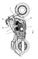
- reference numeral 1 is a V-type 2-cylinder engine for a motorcycle (hereinafter referred to as "engine").
- the engine 1 includes a crank case 2, a front side cylinder 3, a rear side cylinder 4, and a radiator 100.
- Water jackets 3A, 4A (refer to Fig. 3) are formed in the front side cylinder 3 and the rear side cylinder 4.
- the crank case 2 is provided with a right side case 5 and a left side case 6 that is formed integrally with the right side case 5.
- respective ends of water cooling pipes 150, 160 at one side thereof are connected to the front side cylinder 3 and the rear side cylinder 4 of the engine 1, and the other ends of the water cooling pipes 150, 160 at the other side are connected to the radiator 100 (refer to Fig. 3).
- an intake pipe 40 is connected between the radiator 100 and an intake port 13C of a water pump 13, described hereinafter.
- the right side case 5 includes a periphery wall 5A that has an elliptic shape, a closing section 5B that closes a right end section of the periphery wall 5A, and a partition wall 5C that divides the right side case 5 into a clutch chamber A that accommodates a clutch plate 10 and the like, and a crank chamber B that accommodates a crank 101 and the like.
- the clutch plate 10 as can be seen in Fig. 6, is accommodated inside the right side case 5 such that it is in a gap between the closing section 5B of the front side case 5 and a cooling water passage 20, described hereinafter.
- the left side case 6 is also provided with a periphery wall 6A, a closing section 6B, and a partition wall 6C. Further, the partition wall 6C divides the left side case 6 to form a generator chamber C that accommodates a generator and the like, and a crank chamber D.
- a main shaft 11 that is positioned toward a rear section of the partition wall 5C is rotatably inserted in a bearing 5D that defines a main shaft support portion inside the right side case 5.
- the clutch plate 10 is provided in an end section of the main shaft 11, and the clutch plate 10 is driven to rotate by driving force of the engine 1 transmitted to the main shaft 11.
- a crank shaft 12 that is positioned toward a front section of the partition wall 5C is rotatably inserted in a bearing 5E that defines a crank shaft support portion inside the right side case 5.
- the crank 101 accommodated in the crank chambers B, D is integrally attached to an end section of the crank shaft 12.
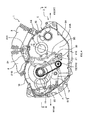
- the water pump 13 is provided inside the crank chamber B of the crank case 2 (at the rear surface side of the partition wall 5C shown in Fig. 4) at a position in the lower section thereof.
- a chain 14 is wrapped around a pump shaft 13A of the water pump 13 and the main shaft 11, and driving force of the main shaft 11 drives the pump shaft 13A to rotate via the chain 14.
- cooling water from the radiator 100 is sucked up through the intake pipe 40 connected to the intake port 13C of the water pump 13 to the water pump 13.
- the cooling water is discharged to the cooling water passage 20 from an outlet port 13B of the water pump 13.
- the pump shaft 13A of the water pump 13 is positioned generally perpendicular to the longitudinal direction of the cooling water passage 20, described hereinafter.
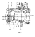
- an oil pump 103 is provided integrally with the water pump 13 and is driven by the pump shaft 13A.
- the pump shaft 13A of the water pump 13 and the pump shaft 103A of the oil pump 103 are formed integrally and coaxially with each other.
- the oil pump 103 maintains pistons (not shown) and the like that are housed in the front side cylinder 3 and the rear side cylinder 4 in a lubricated state.
- the water pump 13 and the oil pump 103 are structured such that, as can be seen in Fig. 11, a mechanical seal 104 and an oil seal 105 seal the cooling water that passes through the water pump 13 from the oil that passes through the oil pump 103.
- the cooling water passage 20 is formed from a first passage section 21, a second passage section 22, a third passage section 23, a fourth passage section 24, and a fifth passage section 25.
- the first passage section 21 extends along a surface of the partition wall 5C that is the inside wall surface of the crank case 2 in the up-down direction.
- the second passage section 22 is formed in a recessed manner inside the crank case 2, has an open upper side, and extends from an upper end 21D of the first passage section 21.
- the third passage section 23 is collectively formed by the crank case 2 and the rear side cylinder 4 and is in communication with the second passage section 22, extending generally rearward and upward from a rear end of the second passage section 22.
- the fourth passage section 24 is formed in the crank case 2, is connected to a front end of the second passage section 22, and extends further forward from the front end side.
- the fifth passage section 25 is collectively formed by the crank case 2 and the front side cylinder 3 and is in communication with the front end of the fourth passage section 24, extending generally forward and upward from the front end of the fourth passage section 24.
- the fifth passage section 25 may correspond to a front side cylinder passage and the third passage 23 may correspond to a rear side cylinder passage. Additionally, the second passage section 22 may correspond to a first intermediate passage and the fourth passage section 24 may correspond to a second intermediate passage. Accordingly, in the arrangement shown, the front side cylinder passage 25 is in fluid communication with the first passage section 21 via both the first and second intermediate passages 22, 24. Additionally, the rear side cylinder passage 23 is in fluid communication with the first passage section 21 via the intermediate passage.
- the fifth passage section 25 may also correspond to a "one side passage", and the second passage section 22 and the third passage section 23 may also correspond to an "other side passage”.
- the first passage section 21 is formed from a passage side wall 21A and a passage cover 21B (refer to Fig. 7 and Fig. 8).
- the passage side wall 21A is a frame like member which defines a channel having a substantially rectangular shape that protrudes out from the surface of the partition wall 5C of the crank case 2 and extends along the surface in a generally up-down direction between an opening of the bearing 5D of the main shaft 11 and an opening of the bearing 5E of the crank shaft 12.
- the passage cover 21B is a plate that has a substantially rectangular shape and is positioned to cover the inside of the passage side wall 21A from the outer side thereof.
- the passage cover 21B is tightly fixed by a plurality of bolts 21C to a top surface of the passage side wall 21A with a gasket (not shown) or the like therebetween. As a result, the passage side wall 21A and the passage cover 21B are held together in a fluid-tight manner.
- the outlet port 13B of the water pump 13 opens to a lower end 21E of the first passage section 21.
- the front end of the second passage section 22 opens in a back section of a passage opening 24A of the fourth passage section 24, described hereinafter.
- the third passage section 23 is connected to the water jacket 4A.
- the fourth passage section 24 is formed from a passage opening 24A and a passage cover 24B (refer to Fig. 9).
- the passage opening 24A is a frame-like member which defines a channel having a substantially rectangular shape that protrudes from the surface of the partition wall 5C of the crank case 2.
- the passage cover 24B is a plate having a substantially rectangular shape that closes the opening of the passage opening 24A.
- the passage cover 24B is tightly fixed by a plurality of bolts 24C to a top surface of the passage opening 24A with a gasket (not shown) or the like therebetween. As a result, the passage opening 24A and the passage cover 24B are held together in a fluid-tight manner.
- the fifth passage section 25 has a lower end that opens in a back section of the passage opening 24A of the fourth passage section 24, and an upper end that is connected to the water jacket 3A.
- cooling water from the radiator 100 is sucked up to the water pump 13 through the intake pipe 40.
- the cooling water is then discharged in the direction indicated by arrow A in Fig. 3 to the first passage section 21 of the cooling water passage 20 from the outlet port 13B of the water pump 13.
- the cooling water that has flown along the first passage section 21 in the direction of arrow A flows along the second passage section 22 in the direction of arrow B in Fig. 3, and also flows in the direction of arrow C along the fourth passage section 24.
- the cooling water flows in the direction of arrow D along the fifth passage section 25, and is fed into the water jacket 3A of the front side cylinder 3, thereby cooling the front side cylinder 3.
- the temperature of the cooling water is increased by cooling the front side cylinder 3.
- the cooling water flows out in the direction of arrow E from an outlet port 3B, and is fed to the radiator 100 where it is cooled.
- the cooling water discharged from the outlet port 13B of the water pump 13 in the direction of arrow A along the first passage section 21 of the cooling water passage 20 also flow in the direction of arrow F from the second passage section 22.
- the cooling water is fed into the water jacket 4A of the rear side cylinder 4, thereby cooling the rear side cylinder 4.
- the temperature of the water is increased by cooling the rear side cylinder 4.
- the cooling water flows out in the direction of arrow G from an outlet port 4B, and is fed to the radiator 100 where it is cooled.
- the engine 1 of the embodiment with the above-described structure includes the cooling water passage 20 formed in the surface of the partition wall 5C that is the inside wall surface of the crank case 2. Further, the water pump 13 is housed inside the crank case 2. Accordingly, the cooling water passage 20 and the water pump 13 are accommodated inside the crank case 2, thereby solving the problem of the cooling water passage 20 and the water pump 13 being exposed to the outside of the engine 1. Accordingly, the engine 1 has an external appearance that is simple, like that of an air-cooled engine, whereby the external appearance of the engine 1 is improved.
- the cooling water passage 20 is formed integrally with the crank case 2 using casting or the like.
- the first passage section 21 of the cooling water passage 20 is formed by the passage side wall 21A that is formed integrally with the surface of the partition wall 5C of the crank case 2 and that extends in the up-down direction, and the passage cover 21B that closes the opening of the passage side wall 21A.
- the first passage section 21 can be formed easily by simply attaching the passage cover 21B to the passage side wall 21A. Accordingly, the workability involved in manufacturing the cooling water passage 20 is enhanced.
- the fourth passage section 24 is also formed by the passage opening 24A that is formed integrally with the surface of the partition wall 5C of the crank case 2, and the passage cover 24B that closes the opening of the passage opening 24A.
- the fourth passage section 24 can be formed easily by simply attaching the passage cover 24B to the opening of the passage opening 24A. Accordingly, the workability involved in manufacturing the cooling water passage 20 is enhanced.
- the main shaft 11 and the crank shaft 12 are provided in the partition wall 5C of the crank case 2, and the first passage section 21 of the cooling water passage 20 is positioned between the main shaft 11 and the crank shaft 12. Accordingly, the cooling water passage 20 can be easily positioned while making use of the space between the main shaft 11 and the crank shaft 12, whereby the design of the layout of the cooling water passage 20 is made simpler. Further, the passage side wall 21A of the first passage section 21 that has a substantially U-shaped cross section is formed integrally with the partition wall 5C of the crank case 2. As a result, the first passage section 21 functions like a cross-beam member of the crank case 2, thereby improving rigidity etc. of the crank case 2.
- the embodiment described is merely exemplary and that various modifications may be made thereto without departing from the scope of the invention.
- the embodiment shown is an example in which the engine 1 is applied to a V-type 2-cylinder engine for a motorcycle.
- the invention is not limited to this structure and may be applied to, for example, a V-type 4-cylinder engine or to an engine of a four-wheeled vehicle.
- one or both of the passage covers 21B, 24B may be provided as part of another component, such as a closing section 5B of the crank case. Additionally, one or both of the passages 21, 24 may be at least partially formed by recesses into an inner wall within the crank case. Additionally further, at least a portion of one or both of the passages 21, 24 may be drilled into a portion of the crankcase.
- a portion or all of the water pump may be positioned externally of the crank case and be in fluid communication with a cooling water passage formed within the crank case.
- the water pump may be entirely or at least partially located within the crank case and be in fluid communication with a cooling water passage located externally of the crank case.
- 1 V-type 2 cylinder engine 2 Crank case, 3 Front side cylinder, 3A, 4A Water jacket, 4 Rear side cylinder, 5 Right side case, 5E Bearing (Crank shaft support portion), 5D Bearing (Main shaft support portion), 6 Left side case, 10 Clutch plate, 11 Main shaft, 12 Crank shaft, 13 Water pump, 13A, 13A Pump shaft of water pump, 20 Cooling water passage, 21 First passage section, 21A Passage side wall, 21B, 24B Passage cover, 22 Second passage section (First intermediate passage), 23 Third passage section (Rear side cylinder passage), 24 Fourth passage section (Second intermediate passage), 25 Fifth passage section (Front side cylinder passage), 103 Oil pump, 103A Pump shaft of oil pump.
Landscapes
- Engineering & Computer Science (AREA)
- Mechanical Engineering (AREA)
- General Engineering & Computer Science (AREA)
- Chemical & Material Sciences (AREA)
- Combustion & Propulsion (AREA)
- Lubrication Of Internal Combustion Engines (AREA)
- Cylinder Crankcases Of Internal Combustion Engines (AREA)
Applications Claiming Priority (1)
| Application Number | Priority Date | Filing Date | Title |
|---|---|---|---|
| JP2006039688A JP2007218173A (ja) | 2006-02-16 | 2006-02-16 | エンジン |
Publications (1)
| Publication Number | Publication Date |
|---|---|
| EP1820947A2 true EP1820947A2 (de) | 2007-08-22 |
Family
ID=37882548
Family Applications (1)
| Application Number | Title | Priority Date | Filing Date |
|---|---|---|---|
| EP07250121A Withdrawn EP1820947A2 (de) | 2006-02-16 | 2007-01-12 | Brennkraftmaschine |
Country Status (3)
| Country | Link |
|---|---|
| US (1) | US7481186B2 (de) |
| EP (1) | EP1820947A2 (de) |
| JP (1) | JP2007218173A (de) |
Families Citing this family (8)
| Publication number | Priority date | Publication date | Assignee | Title |
|---|---|---|---|---|
| US8539929B2 (en) * | 2009-11-18 | 2013-09-24 | Harley-Davidson Motor Company | Cylinder head cooling system |
| CN102220919A (zh) * | 2011-05-27 | 2011-10-19 | 北京中清能发动机技术有限公司 | V型曲柄圆滑块内燃机机体及应用该机体的内燃机 |
| FR3016396A1 (fr) * | 2014-01-13 | 2015-07-17 | Rdmo | Corps de pompe integree dans le carter d'un moteur a refroidissement liquide |
| JP6676944B2 (ja) * | 2015-12-08 | 2020-04-08 | スズキ株式会社 | 水冷式エンジン |
| USD839921S1 (en) * | 2016-08-22 | 2019-02-05 | Harley-Davidson Motor Company Group, LLC | Engine |
| JP6943538B2 (ja) * | 2019-09-30 | 2021-10-06 | 本田技研工業株式会社 | 鞍乗型車両 |
| JP7007342B2 (ja) * | 2019-09-30 | 2022-01-24 | 本田技研工業株式会社 | 鞍乗型車両 |
| CN114109641B (zh) * | 2021-11-10 | 2024-02-27 | 力帆科技(集团)股份有限公司 | 摩托车发动机冷却水道结构 |
Family Cites Families (8)
| Publication number | Priority date | Publication date | Assignee | Title |
|---|---|---|---|---|
| JPS6095150A (ja) * | 1983-10-28 | 1985-05-28 | Mitsubishi Electric Corp | 内燃機関の空燃比制御装置 |
| JPH01315650A (ja) | 1989-05-12 | 1989-12-20 | Honda Motor Co Ltd | エンジンの冷却水通路構造 |
| JP4021068B2 (ja) * | 1998-09-14 | 2007-12-12 | 本田技研工業株式会社 | 自動二輪車用v型内燃機関 |
| JP2001132468A (ja) * | 1999-11-11 | 2001-05-15 | Kawasaki Heavy Ind Ltd | V型液冷式エンジンの冷却液通路構造 |
| JP3442760B2 (ja) * | 2001-12-03 | 2003-09-02 | 本田技研工業株式会社 | 並列4気筒エンジン |
| JP2003293720A (ja) * | 2002-03-29 | 2003-10-15 | Fuji Heavy Ind Ltd | ドライサンプ式エンジン |
| JP2005344559A (ja) * | 2004-06-01 | 2005-12-15 | Suzuki Motor Corp | エンジンの冷却構造 |
| JP4444056B2 (ja) * | 2004-09-30 | 2010-03-31 | 本田技研工業株式会社 | エンジンの冷却構造 |
-
2006
- 2006-02-16 JP JP2006039688A patent/JP2007218173A/ja active Pending
-
2007
- 2007-01-12 EP EP07250121A patent/EP1820947A2/de not_active Withdrawn
- 2007-02-12 US US11/674,016 patent/US7481186B2/en active Active
Also Published As
| Publication number | Publication date |
|---|---|
| US7481186B2 (en) | 2009-01-27 |
| JP2007218173A (ja) | 2007-08-30 |
| US20070186879A1 (en) | 2007-08-16 |
Similar Documents
| Publication | Publication Date | Title |
|---|---|---|
| EP1820947A2 (de) | Brennkraftmaschine | |
| US6598595B2 (en) | Breather device for motorcycle | |
| CN101149014B (zh) | 具有排风管道的内燃机及装载有该内燃机的车辆 | |
| CN105849378B (zh) | 发动机的冷却通路结构 | |
| JP4830000B2 (ja) | 内燃機関の流体通路構造 | |
| JP5932574B2 (ja) | 車両用水冷式内燃機関 | |
| US9266421B2 (en) | Cooling system structure for vehicular water-cooled internal combustion engine | |
| JP5238629B2 (ja) | エアクリーナ | |
| CN100434663C (zh) | 发动机动力传动系统罩盖 | |
| US20050263110A1 (en) | Cooling structure of engine | |
| US8925512B2 (en) | Support structure for water-cooled internal combustion engine | |
| JP5806072B2 (ja) | エンジンのオイルジェット構造 | |
| JP2017125467A (ja) | 内燃機関の冷却構造 | |
| JP6613808B2 (ja) | エンジン及び自動二輪車 | |
| JP4901619B2 (ja) | 内燃機関のブリーザ装置 | |
| US6631780B1 (en) | Engine with torque converter | |
| CN109386363B (zh) | 内燃机的排气结构 | |
| JP2018168815A (ja) | 内燃機関のフロントカバー | |
| JP6601148B2 (ja) | エンジンの潤滑構造及び自動二輪車 | |
| JP6665708B2 (ja) | エンジンのオイル通路構造 | |
| JP2002089217A (ja) | エンジンのオイルポンプ構造 | |
| JP4101619B2 (ja) | 自動二輪車の冷却通路構造 | |
| ITTO980685A1 (it) | Dispositivo di raffreddamento per motori a combustione interna raf- freddati ad acqua | |
| JP2004245110A (ja) | エンジンの排気浄化装置 | |
| JP3852735B2 (ja) | 内燃機関の潤滑装置 |
Legal Events
| Date | Code | Title | Description |
|---|---|---|---|
| PUAI | Public reference made under article 153(3) epc to a published international application that has entered the european phase |
Free format text: ORIGINAL CODE: 0009012 |
|
| AK | Designated contracting states |
Kind code of ref document: A2 Designated state(s): AT BE BG CH CY CZ DE DK EE ES FI FR GB GR HU IE IS IT LI LT LU LV MC NL PL PT RO SE SI SK TR |
|
| AX | Request for extension of the european patent |
Extension state: AL BA HR MK YU |
|
| STAA | Information on the status of an ep patent application or granted ep patent |
Free format text: STATUS: THE APPLICATION HAS BEEN WITHDRAWN |
|
| 18W | Application withdrawn |
Effective date: 20100528 |