EP1820955A2 - Système de moteur aérobie et anaérobie intégré - Google Patents
Système de moteur aérobie et anaérobie intégré Download PDFInfo
- Publication number
- EP1820955A2 EP1820955A2 EP07250522A EP07250522A EP1820955A2 EP 1820955 A2 EP1820955 A2 EP 1820955A2 EP 07250522 A EP07250522 A EP 07250522A EP 07250522 A EP07250522 A EP 07250522A EP 1820955 A2 EP1820955 A2 EP 1820955A2
- Authority
- EP
- European Patent Office
- Prior art keywords
- assembly
- engine
- gas
- nozzle
- turbine engine
- Prior art date
- Legal status (The legal status is an assumption and is not a legal conclusion. Google has not performed a legal analysis and makes no representation as to the accuracy of the status listed.)
- Withdrawn
Links
Images






Classifications
-
- F—MECHANICAL ENGINEERING; LIGHTING; HEATING; WEAPONS; BLASTING
- F02—COMBUSTION ENGINES; HOT-GAS OR COMBUSTION-PRODUCT ENGINE PLANTS
- F02K—JET-PROPULSION PLANTS
- F02K1/00—Plants characterised by the form or arrangement of the jet pipe or nozzle; Jet pipes or nozzles peculiar thereto
- F02K1/06—Varying effective area of jet pipe or nozzle
- F02K1/10—Varying effective area of jet pipe or nozzle by distorting the jet pipe or nozzle
-
- F—MECHANICAL ENGINEERING; LIGHTING; HEATING; WEAPONS; BLASTING
- F02—COMBUSTION ENGINES; HOT-GAS OR COMBUSTION-PRODUCT ENGINE PLANTS
- F02K—JET-PROPULSION PLANTS
- F02K3/00—Plants including a gas turbine driving a compressor or a ducted fan
- F02K3/02—Plants including a gas turbine driving a compressor or a ducted fan in which part of the working fluid by-passes the turbine and combustion chamber
- F02K3/04—Plants including a gas turbine driving a compressor or a ducted fan in which part of the working fluid by-passes the turbine and combustion chamber the plant including ducted fans, i.e. fans with high volume, low pressure outputs, for augmenting the jet thrust, e.g. of double-flow type
- F02K3/06—Plants including a gas turbine driving a compressor or a ducted fan in which part of the working fluid by-passes the turbine and combustion chamber the plant including ducted fans, i.e. fans with high volume, low pressure outputs, for augmenting the jet thrust, e.g. of double-flow type with front fan
-
- F—MECHANICAL ENGINEERING; LIGHTING; HEATING; WEAPONS; BLASTING
- F02—COMBUSTION ENGINES; HOT-GAS OR COMBUSTION-PRODUCT ENGINE PLANTS
- F02C—GAS-TURBINE PLANTS; AIR INTAKES FOR JET-PROPULSION PLANTS; CONTROLLING FUEL SUPPLY IN AIR-BREATHING JET-PROPULSION PLANTS
- F02C3/00—Gas-turbine plants characterised by the use of combustion products as the working fluid
- F02C3/32—Inducing air flow by fluid jet, e.g. ejector action
-
- F—MECHANICAL ENGINEERING; LIGHTING; HEATING; WEAPONS; BLASTING
- F02—COMBUSTION ENGINES; HOT-GAS OR COMBUSTION-PRODUCT ENGINE PLANTS
- F02K—JET-PROPULSION PLANTS
- F02K1/00—Plants characterised by the form or arrangement of the jet pipe or nozzle; Jet pipes or nozzles peculiar thereto
- F02K1/36—Plants characterised by the form or arrangement of the jet pipe or nozzle; Jet pipes or nozzles peculiar thereto having an ejector
-
- F—MECHANICAL ENGINEERING; LIGHTING; HEATING; WEAPONS; BLASTING
- F02—COMBUSTION ENGINES; HOT-GAS OR COMBUSTION-PRODUCT ENGINE PLANTS
- F02K—JET-PROPULSION PLANTS
- F02K9/00—Rocket-engine plants, i.e. plants carrying both fuel and oxidant therefor; Control thereof
- F02K9/74—Rocket-engine plants, i.e. plants carrying both fuel and oxidant therefor; Control thereof combined with another jet-propulsion plant
- F02K9/78—Rocket-engine plants, i.e. plants carrying both fuel and oxidant therefor; Control thereof combined with another jet-propulsion plant with an air-breathing jet-propulsion plant
-
- F—MECHANICAL ENGINEERING; LIGHTING; HEATING; WEAPONS; BLASTING
- F02—COMBUSTION ENGINES; HOT-GAS OR COMBUSTION-PRODUCT ENGINE PLANTS
- F02K—JET-PROPULSION PLANTS
- F02K9/00—Rocket-engine plants, i.e. plants carrying both fuel and oxidant therefor; Control thereof
- F02K9/80—Rocket-engine plants, i.e. plants carrying both fuel and oxidant therefor; Control thereof characterised by thrust or thrust vector control
- F02K9/84—Rocket-engine plants, i.e. plants carrying both fuel and oxidant therefor; Control thereof characterised by thrust or thrust vector control using movable nozzles
Definitions
- the present invention provides a single-stage-to-orbit engine system that can be used with a vehicle suitable for horizontal takeoffs and horizontal landings.
- An engine assembly includes a gas-turbine engine having a tailcone portion and a bypass duct, a rocket engine combustion assembly located at the tailcone portion of the gas-turbine engine, and a movable nozzle segment subassembly that is selectively engageable with the gas-turbine engine bypass duct in an open position and with the rocket engine combustion assembly in a closed position.
- the present invention provides a single-stage-to-orbit engine system that can be used with a vehicle suitable for horizontal takeoffs and horizontal landings.
- the engine system provides an integrated airbreathing and non-airbreathing propulsion system.
- a conventional horizontal takeoff can be achieved as the engine system operates like an airbreathing gas-turbine engine.
- the engine system can transition to operate like a non-airbreathing rocket engine and propel the vehicle further to orbit.
- a convertible nozzle and ejector duct assembly is utilized to transition the engine from airbreathing to non-airbreathing operation, or vice-versa.
- single-stage-to-orbit means that no engine or fuel supply components are jettisoned during takeoff and the climb to orbit. Space is recognized as beginning at an altitude of 100 km (62 miles).
- the present invention relates to travel to orbital altitudes of about 120 to 500 km or more where conditions of microgravity exist.
- the engine system of the present invention can be utilized at speeds below hyper-sonic speeds (i.e., at speeds below about Mach 9).
- FIGS. 1A and 1B are perspective views of an engine system 100 that includes a convertible nozzle and ejector duct assembly 102 that can be selectively moved between open and closed positions.
- the nozzle and ejector duct assembly 102 is in an open position suitable for airbreathing operation of the engine system 100.
- the nozzle and ejector duct assembly 102 is in a closed position suitable for non-airbreathing operation of the engine system 100.
- FIG. 2 is a schematic representation of the engine system 100, which generally includes a gas-turbine engine assembly, a rocket engine assembly, and a convertible nozzle and ejector duct assembly 102.
- the gas-turbine engine assembly can be a conventional gas-turbine engine, for example, a PW4000 family aircraft engine available from Pratt & Whitney, East Hartford, CT.
- the gas-turbine engine assembly includes a nosecone 110, a fan 112, a fan containment structure 114, a low-pressure compressor subassembly 116, a high-pressure compressor subassembly 118, a high-pressure turbine subassembly 120, a low-pressure turbine subassembly 122, a shaft assembly 124 positioned at an engine centerline C L , a bypass duct 126, and a turbine exhaust case 128.
- a tailcone portion 130 is located at the aft end of the gas turbine engine assembly, adjacent to the turbine exhaust case 128.
- the rocket engine assembly can be a conventional rocket engine, for example a RL60 or RL10B-2 cryogenic rocket engine, available from Pratt & Whitney.
- the rocket engine assembly is mounted at the tailcone portion 130 of the gas-turbine engine, along the engine centerline C L , and includes an injector assembly 132 and converging-diverging combustion chamber 134.
- a first strut assembly 136 (also called the J-strut assembly) is connected relative to an aft portion of rocket engine assembly.
- a second strut assembly 138 (also called the I-strut assembly) is connected relative to a forward portion of the rocket engine assembly.
- the strut assemblies 136 and 138 are described in more detail below.
- the convertible nozzle and ejector duct assembly 102 is shown in two positions: an open position 102 o and a closed position 102 c (shown in phantom).
- the assembly 102 forms a portion of an ejector duct for the gas-turbine engine assembly for airbreathing operation of the engine system 100.
- Movable nozzle segments of the assembly 102 are operatively engaged with the first strut assembly 136, which drives and guides those movable segments.
- the assembly 102 engages with the combustion chamber 134 of the rocket engine assembly to form a diverging nozzle suitable for non-airbreathing operation of the engine system 100.
- FIG. 3 is a perspective view of the convertible nozzle and ejector assembly 102 in an open position.
- the convertible nozzle and ejector assembly 102 includes an ejector duct segment subassembly 200 made up of a plurality of ejector duct segments 200A-200F.
- Each ejector duct segment 200A-200F is fixed relative to an airframe anchor location of the engine system 100, meaning each segment 200A-200F is fixed relative to the frame of the vehicle in which the engine system 100 is installed.
- the convertible nozzle and ejector assembly 102 further includes a nozzle segment subassembly 202 made up of a plurality of movable nozzle segments 202A-202F.
- Each of the ejector duct segments 200A-200F can have a side portion surface shape that is formed by rotating an edge 203 of a nozzle segment 202A-202F about the engine centerline C L . This allows the nozzle segments 202A-202F to mate with their adjacent ejector duct segments 200A-200F in an open position.
- the interior surface of ejector duct segments 200A-200F can have a contoured surface for aerodynamic airbreathing opeation between their 203 side surfaces.
- the ejector duct segment subassembly 200 and the nozzle segment subassembly 202 mate together when in an open position. Sealed, mating arrangements of the assembly 102 components is facilitated by maintaining the edges of the ejector duct segments 200A-200F in fixed positions. Although it should be recognized that in further embodiments, portions of the ejector duct segments 200A-200F can be movable to facilitate transitioning the assembly 102 between open and closed positions, as will be explained further below.
- the convertible nozzle and ejector assembly 102 defines a nearly-circular nozzle exit area of about 35,758.63 cm 2 (5,542.6 in 2 ). It should be recognized that in further embodiments, the particular shape and size of the nozzle exit area defined by the assembly 102 can vary as desired.
- FIGS. 4A and 4B are perspective views of the nozzle segment assembly 202 in an open position and a closed position, respectively.
- Each of the nozzle segments 202A-202F includes a pivot support 204 at its aft end, a retainer assembly 206 at its forward end, and can include strengthening structures 208 between its forward and aft ends (reference numbers for subcomponents of nozzle segments 202A and 202C-202F have been omitted in FIGS. 4A and 4B for clarity).
- Each nozzle segment 202A-202F has a bell-shaped interior surface for rocket engine operation and is narrower at its forward end than at its aft end.
- the pivot support 204 is designed to pivotally engage with a pivot mounting bracket (see FIG. 5) to support the aft end of each nozzle segment 202A-202F while permitting movement of the forward end of the nozzle segments 202A-202F.
- the retainer assembly 206 (see also FIG. 12) is designed to operatively engage with the first strut assembly 136 (see FIG. 5) to guide the forward end of each nozzle segment 202A-202F as it moves between open and closed positions.
- the strengthening structures 208 can be external structures as shown in FIGS. 4A and 4B or can be internal structures. The particular shape and configuration of the strengthening structures will vary as desired, and can include rib-like formations that increase strength and rigidity while helping to limit the mass of each nozzle segment 202A-202F.
- joint locations 210 are each located in planes that contain the engine centerline C L (see FIG. 2), and a seal can be formed at each joint location 210 between the adjacent nozzle segments 202A-202F.
- FIG. 5 is a perspective view of a portion of the convertible nozzle and ejector assembly 102 in the closed position.
- each ejector duct segment 200A-200F (only segments 200A and 200B are shown in FIG. 5) includes strengthening structures 208 similar to those on the nozzle segments 202A-202F described above.
- each ejector duct segment 200A-200F has a pivot mounting bracket 212 at its aft end for pivotally supporting portions of adjacent nozzle segment pivot supports 204.
- a first strut assembly 136 (see also FIGS. 9 and 10) is located at the forward end of the convertible nozzle and ejector duct assembly 102 (only one strut 136A is shown in FIG. 5).
- the strut 136A is fixed relative to the ejector duct subassembly 200, and therefore is fixed relative to an airframe of a vehicle in which it is installed.
- An actuator assembly 220 is provided adjacent to the first strut assembly 136 for providing a driving force to move each of the nozzle segments 202A-202F (see also FIG. 11).
- the actuator assembly can be mounted at an outer end of each strut assembly 136, that is, at an end spaced furthest from the engine centerline C L .
- a guide assembly 222 is located along a trailing edge of each strut in the strut assembly 136.
- the retainer assemblies 206 of the nozzle segments 202A-202F engage and retain the guide assemblies 222, such that the forward ends of the movable nozzle segments 202A-202F can be guided along the trailing edges of the respective struts of the first strut assembly 136.
- a flexible, screw-type drive shaft 224 is supported adjacent to each guide assembly 222 at the trailing edge of each strut in the first strut assembly 136.
- the drive shafts 224 are positioned within the guide assemblies 222.
- Each drive shaft 224 is connected to one of the actuator assemblies 220 and is engaged with the retainer assembly 206 of the corresponding nozzle segment 202A-202F. In this way, force generated by the actuator assembly 220 can be transmitted to the drive shaft 224 to move the nozzle segments 202A-202F between the open and closed positions, with the retainer assemblies 206 moving along the paths formed by the guide assemblies 222.
- the particular flexible drive shaft 224 described above is provided merely by way of example, and other types of mechanisms can be used. For instance, a chain-drive system can be used instead of a flex-drive system.
- FIG. 6 is a perspective view of a tailcone assembly that includes the first strut assembly 136 and the second strut assembly 138 mounted at the tailcone portion 130 of the engine system 100.
- FIG. 7 is a cross-sectional view of the tailcone assembly 130, as viewed along line 7-7 of FIG. 6. As shown in FIGS. 6 and 7, the first and second strut assemblies 136 and 138 are secured to the tailcone portion 130 of the engine system 100. The first strut assembly 136 is secured relative to the aft end of the tailcone portion 130, and the second strut assembly 138 is connected relative to the forward end of the tailcone portion 130. The first strut assembly is configured to connect to the rocket combustion chamber 134.
- the individual struts 136A-136F of the first strut assembly 136 extend radially outward from the tailcone portion 130 and are arranged in a spaced circumferential pattern that corresponds to the location and arrangement of the nozzle segment subassembly 202.
- the struts 138A-138E of the second strut assembly 138 are connected to the injector assembly 132 of the rocket engine assembly.
- the individual struts 138A-138E extend radially outward from the tailcone portion 130 and are arranged in a spaced circumferential pattern that corresponds to the location and arrangement of the airfoils which are part of the turbine exhaust case assembly 128.
- FIG. 8 is an exploded perspective view of a portion of the rocket engine assembly.
- the rocket engine assembly includes a low pressure turbine bearing compartment cover 230 (which is also part of the turbine exhaust case assembly 128), a thermal protection dome 232, a combustion chamber mount 234, bolt fasteners 236, oxidizer flow turnaround tube assemblies 238, oxidizer flow diverter plates 240, an oxidizer dome 242, an injector body 244 having oxidizer pintles, an injector body face plate 246, a combustion chamber discharge collection manifold exterior closeout ring 248, a combustion chamber discharge outer turn-around manifold 250, and a combustion chamber discharge collection manifold interior closeout ring 252.
- a portion of the combustion chamber 134 is shown adjacent to the combustion chamber discharge outer turn-around manifold 250.
- Various components of the rocket engine assembly are secured by welding, and weld beads 254 are shown to represent welded connections.
- the rocket engine assembly can be mounted aft of the low pressure turbine assembly 122 of the gas-turbine engine assembly, at the tailcone portion 130.
- the oxidizer turn-around tube assemblies 238 are each connected to struts of the second strut assembly 138 (see FIGS. 7, 14 and 16), and supply an oxidizer fluid (e.g., liquid oxygen, nitrogen tetroxide, and hydrogen peroxide) to the injector assembly 132.
- an oxidizer fluid e.g., liquid oxygen, nitrogen tetroxide, and hydrogen peroxide
- the rocket engine assembly viewed in isolation, operates in a conventional manner well known to those of ordinary skill in the art.
- the gas-turbine engine assembly (see FIG. 2), viewed in isolation, operates in a conventional manner well known to those of ordinary skill in the art.
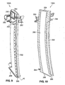
- FIG. 9 is a perspective view of the strut 136A from the first strut assembly 136.
- FIG. 10 is a cross-sectional view of the strut 136A, as viewed along line 10-10 of FIG. 9.
- Other struts 136B-136F of the strut assembly 136, shown in FIG. 6, are substantially identical to the strut 136A.
- the strut 136A is an elliptically-shaped (in a direction tangential to the engine's centerline C L ) hollow member having an interior cavity 280.
- the interior cavity 280 has an inlet opening 282 near an outer end 284 of the strut 136A, and an outlet opening 286 near an inner end 288 of the strut 136A.
- the strut 136A performs multiple functions, including assisting in mechanically moving the convertible nozzle and ejector duct assembly 102 between open and closed positions, providing structural support to the rocket engine assembly, and providing a fuel supply path to the rocket
- the inlet opening 282 permits the introduction of a fluid, such as a liquid fuel, to the strut 136A.
- the inlet opening 282 is connected to a fuel supply manifold (see FIGS. 1A, 1B and 13) to permit a suitable rocket fuel (e.g., liquid hydrogen, a conventional kerosene or kerosene-based rocket fuel, etc.) to be supplied to the strut 136A from vehicle fuel tanks (not shown).
- a suitable rocket fuel e.g., liquid hydrogen, a conventional kerosene or kerosene-based rocket fuel, etc.
- the outlet opening 286 allows fluid to pass out of the strut 136A to conventional cooling channels formed in the walls of the rocket combustion chamber 134.
- the outlet opening 286 is positioned adjacent to the aft, diverging portion of the rocket combustion chamber 134 (see FIGS. 2, 6, 7 and 16).
- the strut 136A has an actuator support structure 290 near its outer end 284 for mounting the actuator assembly 220 to the strut 136A, and a nozzle segment support 292 near its outer end 284 for supporting the forward ends of adjacent nozzle segments 202 when in the open position.
- the strut 136A also has an inner support flange 294 to facilitate securing the strut 136A to the tailcone portion 130 of the engine system 100.
- the strut 136 must have substantial structural support, because it is located within the exhaust path of the gas-turbine engine assembly. Bolts and welding are used to structurally secure the strut 136A, as well as to provide suitable seals to prevent leakage of fluid passing through the interior cavity 280.
- Fuel pumped through the strut 136A cools the strut 136A, to prevent damage from high temperatures generated within the engine system 100.
- the rocket combustion chamber 134 utilizes conventional fuel coolant paths in the chamber walls (not specifically shown), and the fuel can pass from the outlet opening 286 to the fuel coolant paths of the rocket combustion chamber 134.
- the guide assembly 222 is positioned at the trailing edge of the strut 136A.
- the strut 136A has an arcuate shape along its trailing edge, between its outer and inner ends 284 and 288, in order to provide an arcuate path for the forward end of the corresponding segment of the pivoting nozzle segment subassembly 202.
- the particular size and shape of the strut 136 will vary depending on the particular application.
- the elliptical shape of the strut 136 can form a conventional airfoil shape of desired aerodynamic characteristics.
- FIG. 11 is a perspective view of the actuator assembly 220, which is used to provide a driving force to move the nozzle segment subassembly 202.
- the actuator assembly 220 includes a rotary-output motor 300 (e.g., an electric motor having a suitable torque output), a number of bevel gears 302, a number of torque transmission shafts 304, a drive shaft engagement gear 306, and the flexible drive shaft 224.
- the actuator assembly 220 is configured to transmit torque that selectively rotates the drive shaft 224.
- FIG. 12 is a perspective view of the retainer assembly 206 attached to the forward end of the nozzle segment 202A.
- the retainer assembly 206 includes a drive shaft engagement groove 310 and a pair of opposed wheel assemblies 312A and 312B.
- the drive shaft engagement groove 310 engages the drive shaft 224, and is urged outward (to move the nozzle segment 202A toward an open position) or inward (to move the nozzle segment 202A toward a closed position) due to contact with threads of the drive shaft 224 as the drive shaft 224 is rotated by the motor 300 and gearing 302, 304 and 306.
- the opposed wheel assemblies 312A and 312B engage the guide assembly 222 to help guide the nozzle segment 202A along a desired path between its open and closed positions. Moreover, the opposed wheel assemblies 312A and 312B and the guide assembly 222 jointly help maintain engagement of the retainer assembly 206 and the drive shaft 224.
- actuator assemblies 220 can be utilized, such as universal-joint connected gang drive shafts or flexible drive shafts with a single drive motor instead of separate actuator assemblies at each strut assembly 136 and therefore the particular features of the actuator assembly 220 can vary accordingly.
- the first strut assembly 136 functions not only to facilitate mechanically opening and closing the convertible nozzle and ejector duct assembly and structurally supporting the rocket engine assembly, but also to supply fluid, such as fuel, to the rocket engine assembly.
- Fuel can be supplied to the first strut assembly 136 by a fuel supply manifold.
- FIG. 13 is a perspective view of a fuel supply manifold 320.
- the fuel supply manifold 320 has a generally circular body portion 322 that is sized to fit at a circumference of the engine system 100 (see FIG. 1A).
- a number of supply passage structures 324A-324F extend from the body 322, and are configured for mated, sealed attachment to the fluid inlet openings 282 in the struts 136A-136F of the first strut assembly 136.
- inlet flanges 326A-326F are provided to accept fuel pumped to the manifold 320 from a vehicle storage tank.
- fuel supply manifolds can be used.
- individual supply manifolds can be provided for each strut 136A-136F.
- a number of fuel supply manifolds can be provided for groups of two or more of the struts 136A-136F.
- the rocket engine assembly In addition to fuel, the rocket engine assembly must be supplied with an oxidizer to enable non-airbreathing operation of the engine system 100.
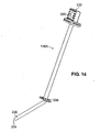
- FIG. 14 is a perspective view of the strut 138A from the second strut assembly 138.
- the strut 138A is substantially similar to the other struts of the second strut assembly 138.
- the strut 138A is hollow, for providing a fluid path between an inlet opening 330 located at an outer end 332 and an outlet opening 334 located at an inner end 336.
- the strut 138A forms an oxidizer supply path through a portion of an exhaust path of the gas-turbine engine to supply oxidizer to the injector assembly 132 of the rocket engine assembly.
- the oxidizer can be a cryogenic fluid, such as liquid oxygen, which can cool the strut 138A.
- the outlet opening 334 can be welded and sealed to the rocket injector assembly 132, and the inlet opening 330 can be connected to an oxidizer supply manifold (see FIG. 15).
- a flange 338 is provided between the opposed ends 332 and 336 of the strut 138A, to secure the strut 138A to the tailcone portion 130 of the engine system 100.
- the oxidizer can be pumped through walls of the rocket combustion chamber 134 to cool it, rather than using fuel to cool the combustion chamber walls.
- the strut 138A can have an airfoil shape, to improve aerodynamic performance. Moreover, the strut 138A can be angled between the flange 338 and the inner end 336 to facilitate attachment between an oxidizer supply manifold and the oxidizer flow turnaround tube assemblies 238, which are part of the injector assembly 132.
- FIG. 15 is a perspective view of an oxidizer supply manifold 340 that includes a generally circular body portion 342, a number of supply passage structures 344A-344E, and a number of inlet flanges 346A-346E.
- the oxidizer supply manifold 340 is sized to fit at a circumference of the engine system 100 (see FIG. 1A), and accepts oxidizer fluid pumped from vehicle oxidizer tanks (not shown) for delivery to the second strut assembly 138 and the rocket engine assembly.
- oxidizer supply manifolds can be used.
- individual supply manifolds can be provided for each strut 138A-138E.
- a number of fuel supply manifolds can be provided for groups of two or more of the struts 138A-138E.
- FIG. 16 is a cross-sectional perspective view of an aft portion of the engine system 100, with a portion of the convertible nozzle and ejector duct assembly 102 shown in the closed position.
- the gas-turbine engine assembly is utilized to produce thrust, with an exhaust flow passing from the turbine exhaust case 128.
- the struts of the second strut assembly 138 are located directly aft of airfoils of the turbine exhaust case 128, for example, strut 138A is located aft of turbine exhaust case airfoil 128A.
- the first and second strut assemblies 136 and 138 are not required to carry fuel and oxidizer during airbreathing operation of the engine system 100. However, in some embodiments, a fluid can be directed through the strut assemblies 136 and 138 to provide cooling.
- the rocket engine assembly is utilized to produce thrust, with an exhaust flow passing from the rocket combustion chamber 134 located at the tailcone portion 130 of the engine system 100.
- Fuel is pumped through the first strut assembly 136 to the rocket combustion chamber 134, and oxidizer is pumped through the second strut assembly 138 to the injector assembly 132.
- the oxidizer and fuel are then combined and burned in a conventional manner.
- suitable rocket fuels include conventional liquid hydrogen and kerosene-based rocket fuels.
- Suitable oxidizers include liquid oxygen, nitrogen tetroxide, and hydrogen peroxide.
- the gas-turbine engine can use a conventional kerosene or kerosene-based jet fuel.
- liquid hydrogen presents numerous problems. For instance, liquid hydrogen has a relatively high density, and is carcinogenic. It may be desirable to utilize a single kerosene or kerosene-based fuel for both airbreathing and non-airbreathing operation of the engine system 100, with liquid oxygen used as the oxidizer for non-airbreathing operation.
- FIG. 17 is a schematic representation of a vehicle 400 utilizing a convertible airbreathing and non-airbreathing engine system 100.
- the vehicle 400 includes conventional airfoil wings 402, to enable horizontal takeoff and landing.
- the wings 402 can be movable to facilitate various takeoff, flight, orbit, and landing maneuvers.
- Optional propellant containers 404 are shown mounted at the wings 402 in FIG. 17. These propellant containers 404 (i.e., self-contained propulsion devices) can release a compressed gas to provide thrust during a transition between airbreathing and non-airbreathing operation of the engine system 100 of the vehicle 400.
- the vehicle 400 is merely an exemplary embodiment, and the engine system 100 can be utilized with different types of vehicles. Moreover, the placement of the engine system 100 on or in the vehicle can vary.
- the operation of the engine system 100 can be understood in the context of a single-stage-to-orbit flight and landing.
- Thefollowing is a discussion of how the various components of the vehicle 400 work together to provide an integral airbreathing and non-airbreathing engine system 100 that enables horizontal takeoff and horizontal landing.
- FIG. 18 is a flow chart illustrating the operation of the vehicle 400.
- the vehicle 400 is filled with oxidizer and fuel (step 500) and the nozzle segment subassembly 202 is driven to the open position (step 502).
- a conventional horizontal takeoff is then executed from a runway (step 504), with the gas-turbine engine assembly providing thrust.
- the vehicle 400 then performs a climb-out procedure to reach a first speed and altitude (step 506). Suitable speeds and altitudes for the climb-out are approximately Mach 0.9 and approximately 12.192 km (40,000 feet) above sea level, which are speeds and altitudes typical for commercial jet aviation. Faster speeds and higher altitudes are also acceptable.
- a decision can be made whether or not to proceed to orbit (decision step 508). If orbit is not desired, the vehicle 400 can execute a conventional horizontal landing at a landing strip (step 510). Such a landing without travel to orbit means that the engine system 100 works only in an airbreathing mode, and can be undertaken by only utilizing the gas-turbine engine assembly.
- a transition is initiated to begin operation of the rocket engine assembly.
- the rocket fuel is pumped through the first strut assembly 136 (step 512).
- cryogenic oxidizer is pumped through the second strut assembly 138 (step 514).
- the fuel from the first strut assembly is first pumped through the walls of the rocket combustion chamber 134 to provide cooling.
- the oxidizer is pumped directly from the second strut assembly 138 to the injector assembly 132.
- the injector assembly 132 includes an igniter, which is energized to achieve rocket engine ignition (step 516). Ignition of the rocket engine assembly occurs while maintaining gas-turbine engine assembly operation.
- a dual flow thrust stream is formed.
- a high velocity, low pressure rocket flow stream is created at the center of a lower velocity, higher pressure gas-turbine engine flow stream.
- the lower velocity, higher pressure, gas-turbine flow stream acts as a "pneumatic nozzle" to direct the high velocity, low pressure rocket flow stream during this intermediate engine transition phase.
- step 518 fuel supply to the gas-turbine engine is stopped.
- the rotors of the gas-turbine engine assembly can be braked to more quickly arrest their rotation (optional step 520). Thrust transfer from the gas-turbine engine assembly to the rocket engine assembly then begins.
- the convertible nozzle and ejector duct assembly 102 is moved to the closed position to engage the rocket combustion chamber 134 and form a diverging nozzle portion (step 522). Aerodynamic loads across the closing nozzle segment subassembly 202 are balanced between the inner, central (high velocity, low pressure) rocket flow stream and the outer (lower velocity, higher pressure) gas-turbine flow stream, which helps prevent excessive nozzle segment subassembly loading.
- the optional propellant containers 404 can be discharged to provide thrust, in order to assure a relatively constant thrust during the transition between airbreathing and non-airbreathing operation.
- the nozzle segment subassembly 202 then completely closes as the rotor assemblies of the gas-turbine engine assembly come to a complete stop.
- a full rocket thrust chamber profile is achieved when the nozzle segment subassembly 202 is fully closed.
- the engine system 100 is now configured for non-airbreathing operation.
- the vehicle's angle of attack is increased and the vehicle 400 is flown to a second speed and altitude, powered by the rocket engine assembly (step 524).
- Suitable speeds and altitude are those sufficient to reach escape velocity (about 40,233 km/h or 25,000 mph) and travel to an orbital altitude with a microgravity environment (e.g., about 120-500 km above sea level or 75-300 miles above sea level).
- a microgravity environment e.g., about 120-500 km above sea level or 75-300 miles above sea level.
- Engine operation can then be terminated (step 526).
- the vehicle can later travel back toward the Earth's surface, by powering the rocket engine assembly to leave orbit, and can execute a conventional horizontal landing (step 510).
- the entire trip, from takeoff to landing, can be accomplished without jettisoning any booster rockets or other engine or fuel system components.
- This provides single-stage-to-orbit capabilities for the vehicle 400. This is made possible by the engine system 100, which integrally provides both airbreathing and non-airbreathing operation.
- the present invention provides numerous benefits. The following are selected examples. First, by enabling both horizontal takeoff and landings, vertical liftoff is not required. This can greatly reduce stress on vehicle and engine components, and offers the potential for greatly increased safety and reliability. Secondly, the present invention provides for a single-stage-to-orbit engine system and vehicle. This provides for more readily reusable components and systems, which reduces the need for disposal or retrieval of jettisoned parts, as well as reduces the need for reworking and remanufacturing of components. Third, the present invention enables the use of the same or similar fuels for both airbreathing and non-airbreathing operation, which can help reduce the mass of fuel required to be carried on board for orbital flight.
- the present invention provides fuel and oxidizer flow paths through a gas-turbine exhaust path.
- the first and second strut assemblies enable fuel and oxidizer to be delivered to a rocket engine assembly located along an engine centerline (and generally aft of a gas-turbine engine assembly).
Landscapes
- Engineering & Computer Science (AREA)
- Chemical & Material Sciences (AREA)
- Combustion & Propulsion (AREA)
- Mechanical Engineering (AREA)
- General Engineering & Computer Science (AREA)
- Jet Pumps And Other Pumps (AREA)
- Structures Of Non-Positive Displacement Pumps (AREA)
- Fluidized-Bed Combustion And Resonant Combustion (AREA)
Applications Claiming Priority (1)
| Application Number | Priority Date | Filing Date | Title |
|---|---|---|---|
| US11/354,453 US7721524B2 (en) | 2006-02-15 | 2006-02-15 | Integrated airbreathing and non-airbreathing engine system |
Publications (2)
| Publication Number | Publication Date |
|---|---|
| EP1820955A2 true EP1820955A2 (fr) | 2007-08-22 |
| EP1820955A3 EP1820955A3 (fr) | 2011-03-23 |
Family
ID=37995637
Family Applications (1)
| Application Number | Title | Priority Date | Filing Date |
|---|---|---|---|
| EP07250522A Withdrawn EP1820955A3 (fr) | 2006-02-15 | 2007-02-08 | Système de moteur aérobie et anaérobie intégré |
Country Status (6)
| Country | Link |
|---|---|
| US (1) | US7721524B2 (fr) |
| EP (1) | EP1820955A3 (fr) |
| JP (1) | JP2007224906A (fr) |
| KR (1) | KR20070082527A (fr) |
| CA (1) | CA2578554A1 (fr) |
| IL (1) | IL181280A0 (fr) |
Cited By (4)
| Publication number | Priority date | Publication date | Assignee | Title |
|---|---|---|---|---|
| CN106499544A (zh) * | 2016-11-03 | 2017-03-15 | 中国人民解放军国防科学技术大学 | 一种火箭旋翼着陆动力系统 |
| RU2648480C2 (ru) * | 2013-01-18 | 2018-03-26 | Эйрбас Дифенс Энд Спейс Сас | Устройство запуска турбонасоса ракетного двигателя |
| CN109408993A (zh) * | 2018-11-02 | 2019-03-01 | 厦门大学 | 一种外涵内置火箭的涡扇冲压组合发动机的设计方法 |
| WO2020052910A1 (fr) * | 2018-09-12 | 2020-03-19 | Reaction Engines Limited | Module de moteur |
Families Citing this family (16)
| Publication number | Priority date | Publication date | Assignee | Title |
|---|---|---|---|---|
| US8281567B2 (en) * | 2005-07-27 | 2012-10-09 | Aryeh Yaakov Kohn | Deployable rocket engine in a combination jet and rocket engine |
| US9222409B2 (en) | 2012-03-15 | 2015-12-29 | United Technologies Corporation | Aerospace engine with augmenting turbojet |
| US9650997B2 (en) | 2013-03-05 | 2017-05-16 | John Bossard | Rotary turbo rocket |
| GB2519155B (en) * | 2013-10-11 | 2016-10-12 | Reaction Engines Ltd | Engine |
| GB2519156A (en) * | 2013-10-11 | 2015-04-15 | Reaction Engines Ltd | A nozzle arrangement for an engine |
| US20150267615A1 (en) * | 2014-03-21 | 2015-09-24 | Michael Marion McCulley | Alternative fuel rocket augmentation device |
| US11041463B1 (en) | 2015-02-11 | 2021-06-22 | Raytheon Technologies Corporation | Turbine engine structure with oxidizer enhanced mode |
| GB2584696A (en) * | 2019-06-12 | 2020-12-16 | Rolls Royce Plc | Generating electrical power at high thrust conditions |
| US11887129B1 (en) | 2020-02-27 | 2024-01-30 | MeasureOne, Inc. | Consumer-permissioned data processing system |
| CN113123899B (zh) * | 2021-04-19 | 2022-07-15 | 中国人民解放军国防科技大学 | 一种中心引射火箭、rbcc发动机及其燃料喷注方法 |
| US11828200B2 (en) | 2022-02-11 | 2023-11-28 | Raytheon Technologies Corporation | Hydrogen-oxygen fueled powerplant with water and heat recovery |
| US11905914B2 (en) | 2022-02-11 | 2024-02-20 | Rtx Corporation | Liquid hydrogen-liquid oxygen fueled powerplant |
| US11635022B1 (en) | 2022-02-11 | 2023-04-25 | Raytheon Technologies Corporation | Reducing contrails from an aircraft powerplant |
| US12161963B2 (en) | 2022-09-13 | 2024-12-10 | Rtx Corporation | Extracting water vapor from a powerplant exhaust |
| US12071890B1 (en) | 2023-03-08 | 2024-08-27 | Rtx Corporation | Recovering water and/or heat energy from powerplant combustion products |
| US12312996B2 (en) | 2023-05-02 | 2025-05-27 | Rtx Corporation | Aircraft powerplant with steam system and bypass |
Family Cites Families (18)
| Publication number | Priority date | Publication date | Assignee | Title |
|---|---|---|---|---|
| US2676457A (en) * | 1945-11-09 | 1954-04-27 | Fred S Kramer | Combined rocket and jet propulsion |
| US2713243A (en) * | 1946-10-23 | 1955-07-19 | Curtiss Wright Corp | Rocket and turbine engine combination for aircraft |
| US2673445A (en) * | 1949-06-21 | 1954-03-30 | Bruno W Bruckmann | Turbojet and rocket motor combination with hot gas ignition system for nonself-reaction rocket fuels |
| US2960824A (en) * | 1955-08-01 | 1960-11-22 | Rohr Aircraft Corp | Rocket starter for gas turbine |
| US2968146A (en) * | 1956-03-23 | 1961-01-17 | Power Jets Res & Dev Ltd | Convertible turbo-rocket and ram jet engine |
| US3002340A (en) * | 1957-04-05 | 1961-10-03 | United Aircraft Corp | Rocket gas generator for turbofan engine |
| US3229459A (en) * | 1963-11-26 | 1966-01-18 | Adolph J Cervenka | Turbojet-liquid air rocket and fuel system |
| US3308626A (en) * | 1964-06-09 | 1967-03-14 | Daniel E Nelson | Convertible gas turbine-rocket reaction propulsion engine |
| US3316716A (en) * | 1964-07-01 | 1967-05-02 | William J D Escher | Composite powerplant and shroud therefor |
| US4096803A (en) * | 1976-12-27 | 1978-06-27 | The United States Of America As Represented By The Secretary Of The Army | Solid propellant air turbo rocket |
| US4817892A (en) * | 1986-04-28 | 1989-04-04 | Janeke Charl E | Aerospace plane and engine therefor |
| GB2238080B (en) * | 1987-05-26 | 1991-10-09 | Rolls Royce Plc | Improved propulsion system for an aerospace vehicle |
| US5052176A (en) * | 1988-09-28 | 1991-10-01 | Societe Nationale D'etude Et De Construction De Moteurs D'aviation | Combination turbojet-ramjet-rocket propulsion system |
| DE3909050C1 (fr) * | 1989-03-18 | 1990-08-16 | Messerschmitt-Boelkow-Blohm Gmbh, 8012 Ottobrunn, De | |
| FR2648517B1 (fr) | 1989-06-14 | 1994-04-01 | Snecma | Propulseur combine turbofusee statoreacteur a rechauffe et son procede de fonctionnement |
| FR2656382B1 (fr) * | 1989-12-21 | 1994-07-08 | Europ Propulsion | Moteur a propulsion combinee a haute adaptabilite pour aeronef ou avion spatial. |
| US6148609A (en) * | 1999-05-27 | 2000-11-21 | Provitola; Anthony Italo | Turbo-rocket thruster |
| US7305816B2 (en) * | 2004-08-13 | 2007-12-11 | United Technologies Corporation | Rocket augmentation for combined cycle turboaccelerator jet engine |
-
2006
- 2006-02-15 US US11/354,453 patent/US7721524B2/en active Active
-
2007
- 2007-02-08 EP EP07250522A patent/EP1820955A3/fr not_active Withdrawn
- 2007-02-12 IL IL181280A patent/IL181280A0/en unknown
- 2007-02-14 JP JP2007032865A patent/JP2007224906A/ja active Pending
- 2007-02-14 CA CA002578554A patent/CA2578554A1/fr not_active Abandoned
- 2007-02-14 KR KR1020070015123A patent/KR20070082527A/ko not_active Withdrawn
Cited By (6)
| Publication number | Priority date | Publication date | Assignee | Title |
|---|---|---|---|---|
| RU2648480C2 (ru) * | 2013-01-18 | 2018-03-26 | Эйрбас Дифенс Энд Спейс Сас | Устройство запуска турбонасоса ракетного двигателя |
| CN106499544A (zh) * | 2016-11-03 | 2017-03-15 | 中国人民解放军国防科学技术大学 | 一种火箭旋翼着陆动力系统 |
| CN106499544B (zh) * | 2016-11-03 | 2018-01-02 | 中国人民解放军国防科学技术大学 | 一种火箭旋翼着陆动力系统 |
| WO2020052910A1 (fr) * | 2018-09-12 | 2020-03-19 | Reaction Engines Limited | Module de moteur |
| US11661908B2 (en) | 2018-09-12 | 2023-05-30 | Reaction Engines Limited | Airbreathing engine module with reverse flow arrangement |
| CN109408993A (zh) * | 2018-11-02 | 2019-03-01 | 厦门大学 | 一种外涵内置火箭的涡扇冲压组合发动机的设计方法 |
Also Published As
| Publication number | Publication date |
|---|---|
| US20090282806A1 (en) | 2009-11-19 |
| JP2007224906A (ja) | 2007-09-06 |
| US7721524B2 (en) | 2010-05-25 |
| KR20070082527A (ko) | 2007-08-21 |
| CA2578554A1 (fr) | 2007-08-15 |
| EP1820955A3 (fr) | 2011-03-23 |
| IL181280A0 (en) | 2007-07-04 |
Similar Documents
| Publication | Publication Date | Title |
|---|---|---|
| EP1820955A2 (fr) | Système de moteur aérobie et anaérobie intégré | |
| RU2233772C2 (ru) | Система запуска и транспортирования полезной нагрузки | |
| EP3423716B1 (fr) | Système utilisant de l'air comprimé comme source de force et son procédé; aéronef | |
| US10815935B2 (en) | Throttleable propulsion launch escape systems and devices | |
| US9580183B2 (en) | Actuation mechanism for a convertible gas turbine propulsion system | |
| US8511058B2 (en) | Convertible gas turbine propulsion system | |
| EP3617061B1 (fr) | Transmission de propulsion et architecture distribuées mécaniquement | |
| US8955335B2 (en) | System, propulsion system and vehicle | |
| US5149012A (en) | Turbocraft | |
| GB2222635A (en) | A propulsion system for an aerospace vehicle | |
| WO2014021742A2 (fr) | Procédé de déplacement de charges dans l'atmosphère de planètes à des vitesses supérieures à la vitesse orbitale et aéronef ultra-hypersonique multimodal à intégration avancée de la cellule pour sa mise en oeuvre | |
| US20240199237A1 (en) | Launch system and method | |
| RU2682228C2 (ru) | Вращательный механизм | |
| CN210391548U (zh) | 一种竹蜻蜓单桨翼直升机 | |
| US20100251695A1 (en) | Rocket engine for use with aerodynamic fuel ribbon, and fuel ribbon for rocket and method | |
| JP4944270B1 (ja) | ターボシャフト・エンジンのv/stol機 | |
| RU2106511C1 (ru) | Ракетно-турбинный двигатель комбинированного типа | |
| US20230383709A1 (en) | Thrust vectoring exhaust nozzle for aircraft propulsion system | |
| US3103324A (en) | High velocity high altitude v.t.o.l. aircraft | |
| US12228287B1 (en) | Rotating detonation combustor | |
| RU2609547C1 (ru) | Возвращаемая ступень ракеты-носителя и способ ее работы | |
| EP4592510A1 (fr) | Carter intermédiaire pour carter de système de propulsion d'aéronef | |
| US12358615B2 (en) | Pyrotechnic wheel acceleration system | |
| RU2810821C1 (ru) | Ударный авиационный комплекс с беспилотным летательным аппаратом | |
| RU2860045C1 (ru) | Сверхскоростной, сверхвысотный, трехрежимный реактивный двигатель |
Legal Events
| Date | Code | Title | Description |
|---|---|---|---|
| PUAI | Public reference made under article 153(3) epc to a published international application that has entered the european phase |
Free format text: ORIGINAL CODE: 0009012 |
|
| AK | Designated contracting states |
Kind code of ref document: A2 Designated state(s): AT BE BG CH CY CZ DE DK EE ES FI FR GB GR HU IE IS IT LI LT LU LV MC NL PL PT RO SE SI SK TR |
|
| AX | Request for extension of the european patent |
Extension state: AL BA HR MK YU |
|
| PUAL | Search report despatched |
Free format text: ORIGINAL CODE: 0009013 |
|
| AK | Designated contracting states |
Kind code of ref document: A3 Designated state(s): AT BE BG CH CY CZ DE DK EE ES FI FR GB GR HU IE IS IT LI LT LU LV MC NL PL PT RO SE SI SK TR |
|
| AX | Request for extension of the european patent |
Extension state: AL BA HR MK RS |
|
| AKY | No designation fees paid | ||
| REG | Reference to a national code |
Ref country code: DE Ref legal event code: R108 |
|
| REG | Reference to a national code |
Ref country code: DE Ref legal event code: R108 Effective date: 20111130 |
|
| STAA | Information on the status of an ep patent application or granted ep patent |
Free format text: STATUS: THE APPLICATION IS DEEMED TO BE WITHDRAWN |
|
| 18D | Application deemed to be withdrawn |
Effective date: 20110924 |