EP1820968A2 - Machine de compression de fluide à spirales - Google Patents
Machine de compression de fluide à spirales Download PDFInfo
- Publication number
- EP1820968A2 EP1820968A2 EP07102582A EP07102582A EP1820968A2 EP 1820968 A2 EP1820968 A2 EP 1820968A2 EP 07102582 A EP07102582 A EP 07102582A EP 07102582 A EP07102582 A EP 07102582A EP 1820968 A2 EP1820968 A2 EP 1820968A2
- Authority
- EP
- European Patent Office
- Prior art keywords
- scroll
- fixed
- orbiting
- driving shaft
- wrap
- Prior art date
- Legal status (The legal status is an assumption and is not a legal conclusion. Google has not performed a legal analysis and makes no representation as to the accuracy of the status listed.)
- Granted
Links
Images


Classifications
-
- F—MECHANICAL ENGINEERING; LIGHTING; HEATING; WEAPONS; BLASTING
- F04—POSITIVE - DISPLACEMENT MACHINES FOR LIQUIDS; PUMPS FOR LIQUIDS OR ELASTIC FLUIDS
- F04C—ROTARY-PISTON, OR OSCILLATING-PISTON, POSITIVE-DISPLACEMENT MACHINES FOR LIQUIDS; ROTARY-PISTON, OR OSCILLATING-PISTON, POSITIVE-DISPLACEMENT PUMPS
- F04C29/00—Component parts, details or accessories of pumps or pumping installations, not provided for in groups F04C18/00 - F04C28/00
- F04C29/04—Heating; Cooling; Heat insulation
-
- F—MECHANICAL ENGINEERING; LIGHTING; HEATING; WEAPONS; BLASTING
- F04—POSITIVE - DISPLACEMENT MACHINES FOR LIQUIDS; PUMPS FOR LIQUIDS OR ELASTIC FLUIDS
- F04C—ROTARY-PISTON, OR OSCILLATING-PISTON, POSITIVE-DISPLACEMENT MACHINES FOR LIQUIDS; ROTARY-PISTON, OR OSCILLATING-PISTON, POSITIVE-DISPLACEMENT PUMPS
- F04C18/00—Rotary-piston pumps specially adapted for elastic fluids
- F04C18/02—Rotary-piston pumps specially adapted for elastic fluids of arcuate-engagement type, i.e. with circular translatory movement of co-operating members, each member having the same number of teeth or tooth-equivalents
- F04C18/0207—Rotary-piston pumps specially adapted for elastic fluids of arcuate-engagement type, i.e. with circular translatory movement of co-operating members, each member having the same number of teeth or tooth-equivalents both members having co-operating elements in spiral form
- F04C18/0215—Rotary-piston pumps specially adapted for elastic fluids of arcuate-engagement type, i.e. with circular translatory movement of co-operating members, each member having the same number of teeth or tooth-equivalents both members having co-operating elements in spiral form where only one member is moving
- F04C18/0223—Rotary-piston pumps specially adapted for elastic fluids of arcuate-engagement type, i.e. with circular translatory movement of co-operating members, each member having the same number of teeth or tooth-equivalents both members having co-operating elements in spiral form where only one member is moving with symmetrical double wraps
Definitions
- the present invention relates to a scroll fluid machine such as a scroll vacuum pump or a scroll compressor.
- a scroll fluid machine comprises a fixed scroll having a spiral fixed wrap and an orbiting scroll having a spiral orbiting wrap.
- the orbiting scroll is revolved by a driving shaft while the fixed wrap engages with the orbiting wrap.
- a compression chamber formed between the fixed and orbiting wraps is gradually decreased in volume and moved towards the center, thereby compressing a compression medium such as a gas sucked through an inlet in the outer circumference and discharging it through an outlet at the center.
- the compression medium is compressed towards the center, so that the temperature of the center rises compared with the outer circumference.
- it is necessary to cool a central part so as to prevent a rotary part of the driving shaft and orbiting scroll such as bearings or seal member from deteriorating owing to heat.
- the compression medium is a toxic gas that contaminates natural environment
- a housing 1 comprises a rear casing 2 and a front cover 3 to form a sealed cylindrical chamber 4.
- An inlet 5 for sucking a gas from an external tank (not shown) into the chamber 4 is formed on the upper outer circumference, and an outlet 6 for discharging a compressed gas from the chamber 4 is formed in the center.
- the outlet 6 is connected to a discharge tube 7 in the lower outer circumference of the cover 3 via a discharge path 61 extending downwards.
- the housing 1 and a motor 10 described below are mounted to a support 1a partially shown in Fig. 1.
- the casing 2 and the cover 3 have circular fixed end plates 21,31 facing each other.
- the opposite surfaces of the fixed end plates 21,31 have involute-curve-like spiral fixed wraps 22,32 to form fixed scroll 23,33.
- orbiting wraps 91,91 are provided respectively to engage with the fixed wraps 22,32 with 180 degree shifting, and the orbiting scroll 9 is connected to the fixed end plate 31 via a known pin-crank-type self-rotation preventing device 15.
- the driving shaft 8 is connected to the motor 10 as drive source at the rear end and rotatably supported by bearings 11,12 in the center of each of the fixed end plates 21,31.
- seals 20,20a,20b are provided between the outer circumferential surface of the driving shaft 6 and the casing 2 or the cover 3, seals 20,20a,20b are provided to prevent a gas from leaking.
- a the front and rear ends which project from the fixed end plates 31,21 of the driving shaft 8, balance weights 13,14 are secured to rotate together with the driving shaft 8 making rotation of the driving shaft 8 smooth.
- covering members 18,19 are mounted to cover the projecting ends of the driving shaft 8 from the housing and the balance weights 13,14.
- the covering members 18,19 prevent a compressed gas in the chamber 4 from leaking.
- the orbiting scroll 9 is revolved by rotating the driving shaft 8 by the motor 10 while the orbiting wraps 91,91 engage with the fixed wraps 22,32.
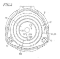
- a plurality of compression chambers 16,16a,16b,16c between the fixed wraps 22,32 and the orbiting wraps 91,91 are moved towards the center as the volume of the compression chamber reduces gradually.
- the adiabatic expansion chamber 17 is formed by removing an innermost winding of a known fixed wrap and is greater in volume than the innermost compression chamber 16c.
- an intake port 324 for introducing a gas compressed by the innermost compression chamber 16c into the adiabatic expansion chamber 17.
- a projection and an intake port (not shown).
- each of the compression chambers 16,16a,16b,16c moves towards the center while each volume gradually decreases thereby compressing gas sucked from the inlet 5.
- Gas finally compressed by the innermost compression chamber 16c is introduced into the adiabatic expansion chamber 17 through the intake port 324.
- Gas in the adiabatic expansion chamber 17 adiabatically expands and falls in temperature because the volume of the adiabatic expansion chamber 17 is greater than that of the innermost compression chamber 16c, thereby cooling the eccentric axial portion 81 of the driving shaft 8 within the adiabatic expansion chamber 17, rotary parts of the orbiting scroll 9 such as the bearings 11,12 and sealing members 20,20a,20b effectively.
- Gas introduced in the adiabatic expansion chamber 17 is discharged to outside or stored in an external tank (not shown) via the outlet 6, the discharge path 61 and the discharge tube 7.
- Gas which is discharged from the outlet 6 of the adiabatic expansion chamber 16c is lower in temperature than gas compressed in the innermost compression chamber 16c thereby cooling part of the scroll fluid machine especially the discharge path 61 when it passes through the discharge path 61.
- the foregoing embodiment relates to a both-side scroll fluid machine where the both-side orbiting scroll 9 is disposed between the two fixed scrolls 23 and 23.
- the present invention may apply to a one-side scroll fluid machine where a one-side fixed scroll engages with a one-side orbiting scroll.
- the adiabatic expansion chamber 17 is disposed inside the innermost winding portions 221,321 of the fixed wraps 22,32 of the fixed scroll 23,33.
- the innermost winding portion of the orbiting wrap 91 may engage within the innermost winding portions 221,321 and the adiabatic expansion chamber 17 may be disposed within the innermost winding portion of the orbiting wrap 91. Similar advantages can be achieved as well.
Landscapes
- Engineering & Computer Science (AREA)
- Mechanical Engineering (AREA)
- General Engineering & Computer Science (AREA)
- Rotary Pumps (AREA)
- Applications Or Details Of Rotary Compressors (AREA)
Applications Claiming Priority (1)
| Application Number | Priority Date | Filing Date | Title |
|---|---|---|---|
| JP2006043703A JP4870445B2 (ja) | 2006-02-21 | 2006-02-21 | スクロール流体機械 |
Publications (3)
| Publication Number | Publication Date |
|---|---|
| EP1820968A2 true EP1820968A2 (fr) | 2007-08-22 |
| EP1820968A3 EP1820968A3 (fr) | 2013-08-07 |
| EP1820968B1 EP1820968B1 (fr) | 2016-07-13 |
Family
ID=38008923
Family Applications (1)
| Application Number | Title | Priority Date | Filing Date |
|---|---|---|---|
| EP07102582.9A Ceased EP1820968B1 (fr) | 2006-02-21 | 2007-02-16 | Machine de compression de fluide à spirales |
Country Status (4)
| Country | Link |
|---|---|
| US (1) | US7341439B2 (fr) |
| EP (1) | EP1820968B1 (fr) |
| JP (1) | JP4870445B2 (fr) |
| CN (1) | CN101025158A (fr) |
Family Cites Families (8)
| Publication number | Priority date | Publication date | Assignee | Title |
|---|---|---|---|---|
| JPH07119634A (ja) * | 1993-10-21 | 1995-05-09 | Kobe Steel Ltd | 往復式圧縮機 |
| JP3637792B2 (ja) * | 1998-11-18 | 2005-04-13 | 株式会社豊田自動織機 | 燃料電池装置 |
| JP2001329970A (ja) * | 2000-05-19 | 2001-11-30 | Fujitsu General Ltd | スクロール圧縮機 |
| JP2003343203A (ja) * | 2002-05-30 | 2003-12-03 | Anest Iwata Corp | 圧縮部と膨張部を備えたスクロール式流体機械 |
| US7121817B2 (en) * | 2002-05-30 | 2006-10-17 | Anest Iwata Corporation | Scroll fluid machine comprising compressing and expanding sections |
| JP3966088B2 (ja) * | 2002-06-11 | 2007-08-29 | 株式会社豊田自動織機 | スクロール型圧縮機 |
| JP4116830B2 (ja) | 2002-06-27 | 2008-07-09 | アネスト岩田株式会社 | スクロール流体機械 |
| JP4542800B2 (ja) * | 2004-03-05 | 2010-09-15 | アネスト岩田株式会社 | スクロール真空ポンプ |
-
2006
- 2006-02-21 JP JP2006043703A patent/JP4870445B2/ja not_active Expired - Fee Related
-
2007
- 2007-02-12 CN CNA2007100050392A patent/CN101025158A/zh active Pending
- 2007-02-16 EP EP07102582.9A patent/EP1820968B1/fr not_active Ceased
- 2007-02-20 US US11/708,655 patent/US7341439B2/en active Active
Also Published As
| Publication number | Publication date |
|---|---|
| US7341439B2 (en) | 2008-03-11 |
| EP1820968B1 (fr) | 2016-07-13 |
| EP1820968A3 (fr) | 2013-08-07 |
| JP4870445B2 (ja) | 2012-02-08 |
| US20070196226A1 (en) | 2007-08-23 |
| JP2007224735A (ja) | 2007-09-06 |
| CN101025158A (zh) | 2007-08-29 |
Similar Documents
| Publication | Publication Date | Title |
|---|---|---|
| JP4999157B2 (ja) | 磁気カップリングを介して駆動源に結合した流体機械 | |
| EP2650541A1 (fr) | Machine de fluide en volute | |
| EP1813813A2 (fr) | Machine de compression de fluide à spirales | |
| JP2012082794A (ja) | スクロール型流体機械 | |
| JP5914810B2 (ja) | スクロール型圧縮機 | |
| CN103291617B (zh) | 涡旋压缩机及空气调和装置 | |
| EP1820968B1 (fr) | Machine de compression de fluide à spirales | |
| JP7481640B2 (ja) | スクロール圧縮機及び冷凍装置 | |
| US9470229B2 (en) | Single screw compressor | |
| JP4448314B2 (ja) | スクロール圧縮機 | |
| CN111156166B (zh) | 涡旋式真空泵 | |
| JP2008164095A (ja) | 磁気カップリング装置 | |
| CN112585357B (zh) | 密闭型压缩机 | |
| EP2108842A1 (fr) | Compresseur à spirales | |
| JP2007332850A (ja) | 流体機械 | |
| JP2009085154A (ja) | スクロール流体機械 | |
| CN216767751U (zh) | 涡旋式压缩机 | |
| JP5149850B2 (ja) | スクロール型流体機械 | |
| JP2015165116A (ja) | スクロール型圧縮機 | |
| CN113454341B (zh) | 涡旋式压缩机 | |
| JP3884101B2 (ja) | オイルフリースクロール真空ポンプ | |
| EP1626178B1 (fr) | Pompe à vide à spirales | |
| GB2099081A (en) | Sliding-vane rotary compressor | |
| JP2012036841A (ja) | 圧縮機 | |
| JP3036927B2 (ja) | スクロール圧縮機 |
Legal Events
| Date | Code | Title | Description |
|---|---|---|---|
| PUAI | Public reference made under article 153(3) epc to a published international application that has entered the european phase |
Free format text: ORIGINAL CODE: 0009012 |
|
| 17P | Request for examination filed |
Effective date: 20070313 |
|
| AK | Designated contracting states |
Kind code of ref document: A2 Designated state(s): AT BE BG CH CY CZ DE DK EE ES FI FR GB GR HU IE IS IT LI LT LU LV MC NL PL PT RO SE SI SK TR |
|
| AX | Request for extension of the european patent |
Extension state: AL BA HR MK YU |
|
| PUAL | Search report despatched |
Free format text: ORIGINAL CODE: 0009013 |
|
| AK | Designated contracting states |
Kind code of ref document: A3 Designated state(s): AT BE BG CH CY CZ DE DK EE ES FI FR GB GR HU IE IS IT LI LT LU LV MC NL PL PT RO SE SI SK TR |
|
| AX | Request for extension of the european patent |
Extension state: AL BA HR MK RS |
|
| RIC1 | Information provided on ipc code assigned before grant |
Ipc: F04C 29/04 20060101ALI20130704BHEP Ipc: F04C 18/02 20060101ALI20130704BHEP Ipc: F04C 2/18 20060101AFI20130704BHEP |
|
| AKX | Designation fees paid |
Designated state(s): DE FR GB |
|
| GRAP | Despatch of communication of intention to grant a patent |
Free format text: ORIGINAL CODE: EPIDOSNIGR1 |
|
| INTG | Intention to grant announced |
Effective date: 20160209 |
|
| GRAS | Grant fee paid |
Free format text: ORIGINAL CODE: EPIDOSNIGR3 |
|
| GRAA | (expected) grant |
Free format text: ORIGINAL CODE: 0009210 |
|
| AK | Designated contracting states |
Kind code of ref document: B1 Designated state(s): DE FR GB |
|
| REG | Reference to a national code |
Ref country code: GB Ref legal event code: FG4D |
|
| REG | Reference to a national code |
Ref country code: DE Ref legal event code: R096 Ref document number: 602007046957 Country of ref document: DE |
|
| REG | Reference to a national code |
Ref country code: FR Ref legal event code: PLFP Year of fee payment: 11 |
|
| REG | Reference to a national code |
Ref country code: DE Ref legal event code: R097 Ref document number: 602007046957 Country of ref document: DE |
|
| PLBE | No opposition filed within time limit |
Free format text: ORIGINAL CODE: 0009261 |
|
| STAA | Information on the status of an ep patent application or granted ep patent |
Free format text: STATUS: NO OPPOSITION FILED WITHIN TIME LIMIT |
|
| 26N | No opposition filed |
Effective date: 20170418 |
|
| REG | Reference to a national code |
Ref country code: FR Ref legal event code: PLFP Year of fee payment: 12 |
|
| PGFP | Annual fee paid to national office [announced via postgrant information from national office to epo] |
Ref country code: FR Payment date: 20230220 Year of fee payment: 17 |
|
| PGFP | Annual fee paid to national office [announced via postgrant information from national office to epo] |
Ref country code: GB Payment date: 20230220 Year of fee payment: 17 Ref country code: DE Payment date: 20220620 Year of fee payment: 17 |
|
| P01 | Opt-out of the competence of the unified patent court (upc) registered |
Effective date: 20230526 |
|
| REG | Reference to a national code |
Ref country code: DE Ref legal event code: R119 Ref document number: 602007046957 Country of ref document: DE |
|
| GBPC | Gb: european patent ceased through non-payment of renewal fee |
Effective date: 20240216 |
|
| PG25 | Lapsed in a contracting state [announced via postgrant information from national office to epo] |
Ref country code: DE Free format text: LAPSE BECAUSE OF NON-PAYMENT OF DUE FEES Effective date: 20240903 |
|
| PG25 | Lapsed in a contracting state [announced via postgrant information from national office to epo] |
Ref country code: GB Free format text: LAPSE BECAUSE OF NON-PAYMENT OF DUE FEES Effective date: 20240216 |
|
| PG25 | Lapsed in a contracting state [announced via postgrant information from national office to epo] |
Ref country code: FR Free format text: LAPSE BECAUSE OF NON-PAYMENT OF DUE FEES Effective date: 20240229 |
|
| PG25 | Lapsed in a contracting state [announced via postgrant information from national office to epo] |
Ref country code: GB Free format text: LAPSE BECAUSE OF NON-PAYMENT OF DUE FEES Effective date: 20240216 Ref country code: FR Free format text: LAPSE BECAUSE OF NON-PAYMENT OF DUE FEES Effective date: 20240229 Ref country code: DE Free format text: LAPSE BECAUSE OF NON-PAYMENT OF DUE FEES Effective date: 20240903 |