EP1820981A2 - Roulement à rouleaux pour mécanisme d'un engrenage planétaire - Google Patents
Roulement à rouleaux pour mécanisme d'un engrenage planétaire Download PDFInfo
- Publication number
- EP1820981A2 EP1820981A2 EP07003147A EP07003147A EP1820981A2 EP 1820981 A2 EP1820981 A2 EP 1820981A2 EP 07003147 A EP07003147 A EP 07003147A EP 07003147 A EP07003147 A EP 07003147A EP 1820981 A2 EP1820981 A2 EP 1820981A2
- Authority
- EP
- European Patent Office
- Prior art keywords
- cage
- planetary gear
- outside diameter
- diameter surface
- pillar
- Prior art date
- Legal status (The legal status is an assumption and is not a legal conclusion. Google has not performed a legal analysis and makes no representation as to the accuracy of the status listed.)
- Withdrawn
Links
Images


Classifications
-
- F—MECHANICAL ENGINEERING; LIGHTING; HEATING; WEAPONS; BLASTING
- F16—ENGINEERING ELEMENTS AND UNITS; GENERAL MEASURES FOR PRODUCING AND MAINTAINING EFFECTIVE FUNCTIONING OF MACHINES OR INSTALLATIONS; THERMAL INSULATION IN GENERAL
- F16C—SHAFTS; FLEXIBLE SHAFTS; ELEMENTS OR CRANKSHAFT MECHANISMS; ROTARY BODIES OTHER THAN GEARING ELEMENTS; BEARINGS
- F16C33/00—Parts of bearings; Special methods for making bearings or parts thereof
- F16C33/30—Parts of ball or roller bearings
- F16C33/46—Cages for rollers or needles
- F16C33/54—Cages for rollers or needles made from wire, strips, or sheet metal
- F16C33/542—Cages for rollers or needles made from wire, strips, or sheet metal made from sheet metal
- F16C33/543—Cages for rollers or needles made from wire, strips, or sheet metal made from sheet metal from a single part
-
- F—MECHANICAL ENGINEERING; LIGHTING; HEATING; WEAPONS; BLASTING
- F16—ENGINEERING ELEMENTS AND UNITS; GENERAL MEASURES FOR PRODUCING AND MAINTAINING EFFECTIVE FUNCTIONING OF MACHINES OR INSTALLATIONS; THERMAL INSULATION IN GENERAL
- F16C—SHAFTS; FLEXIBLE SHAFTS; ELEMENTS OR CRANKSHAFT MECHANISMS; ROTARY BODIES OTHER THAN GEARING ELEMENTS; BEARINGS
- F16C19/00—Bearings with rolling contact, for exclusively rotary movement
- F16C19/22—Bearings with rolling contact, for exclusively rotary movement with bearing rollers essentially of the same size in one or more circular rows, e.g. needle bearings
- F16C19/44—Needle bearings
- F16C19/46—Needle bearings with one row or needles
- F16C19/466—Needle bearings with one row or needles comprising needle rollers and an outer ring, i.e. subunit without inner ring
-
- F—MECHANICAL ENGINEERING; LIGHTING; HEATING; WEAPONS; BLASTING
- F16—ENGINEERING ELEMENTS AND UNITS; GENERAL MEASURES FOR PRODUCING AND MAINTAINING EFFECTIVE FUNCTIONING OF MACHINES OR INSTALLATIONS; THERMAL INSULATION IN GENERAL
- F16C—SHAFTS; FLEXIBLE SHAFTS; ELEMENTS OR CRANKSHAFT MECHANISMS; ROTARY BODIES OTHER THAN GEARING ELEMENTS; BEARINGS
- F16C33/00—Parts of bearings; Special methods for making bearings or parts thereof
- F16C33/30—Parts of ball or roller bearings
- F16C33/46—Cages for rollers or needles
- F16C33/4605—Details of interaction of cage and race, e.g. retention or centring
-
- F—MECHANICAL ENGINEERING; LIGHTING; HEATING; WEAPONS; BLASTING
- F16—ENGINEERING ELEMENTS AND UNITS; GENERAL MEASURES FOR PRODUCING AND MAINTAINING EFFECTIVE FUNCTIONING OF MACHINES OR INSTALLATIONS; THERMAL INSULATION IN GENERAL
- F16H—GEARING
- F16H57/00—General details of gearing
- F16H57/08—General details of gearing of gearings with members having orbital motion
- F16H57/082—Planet carriers
-
- F—MECHANICAL ENGINEERING; LIGHTING; HEATING; WEAPONS; BLASTING
- F16—ENGINEERING ELEMENTS AND UNITS; GENERAL MEASURES FOR PRODUCING AND MAINTAINING EFFECTIVE FUNCTIONING OF MACHINES OR INSTALLATIONS; THERMAL INSULATION IN GENERAL
- F16C—SHAFTS; FLEXIBLE SHAFTS; ELEMENTS OR CRANKSHAFT MECHANISMS; ROTARY BODIES OTHER THAN GEARING ELEMENTS; BEARINGS
- F16C2240/00—Specified values or numerical ranges of parameters; Relations between them
- F16C2240/40—Linear dimensions, e.g. length, radius, thickness, gap
- F16C2240/70—Diameters; Radii
-
- F—MECHANICAL ENGINEERING; LIGHTING; HEATING; WEAPONS; BLASTING
- F16—ENGINEERING ELEMENTS AND UNITS; GENERAL MEASURES FOR PRODUCING AND MAINTAINING EFFECTIVE FUNCTIONING OF MACHINES OR INSTALLATIONS; THERMAL INSULATION IN GENERAL
- F16C—SHAFTS; FLEXIBLE SHAFTS; ELEMENTS OR CRANKSHAFT MECHANISMS; ROTARY BODIES OTHER THAN GEARING ELEMENTS; BEARINGS
- F16C2361/00—Apparatus or articles in engineering in general
- F16C2361/61—Toothed gear systems, e.g. support of pinion shafts
-
- F—MECHANICAL ENGINEERING; LIGHTING; HEATING; WEAPONS; BLASTING
- F16—ENGINEERING ELEMENTS AND UNITS; GENERAL MEASURES FOR PRODUCING AND MAINTAINING EFFECTIVE FUNCTIONING OF MACHINES OR INSTALLATIONS; THERMAL INSULATION IN GENERAL
- F16H—GEARING
- F16H57/00—General details of gearing
- F16H57/08—General details of gearing of gearings with members having orbital motion
- F16H2057/085—Bearings for orbital gears
Definitions
- This invention relates to a roller bearing such as a needle roller bearing incorporated in a planetary gear mechanism in an automatic transmission of an automobile or the like, and more particularly to a roller bearing for a planetary gear mechanism which is of the cage-and-roller type comprising a plurality of rollers and a cage positioning and holding these rollers, and in which an outside diameter surface of the cage is guided by a bore diameter surface of a planetary gear.
- a cage-and-roller type needle roller bearing (This type will hereinafter be referred to as "a needle roller bearing with cage”.) comprising a plurality of needle rollers and a cage positioning and holding these rollers has increasingly been used as a needle roller bearing (serving as a gear inner bearing) interposed between the planetary gear and a planetary gear support shaft passing through the planetary gear.
- a sun gear and a ring gear are arranged in concentric relation to each other, and a plurality of planetary gears are arranged between the sun gear and the ring gear, and support shafts (planetary gear support shafts) of these planetary gears are connected to and held by a carrier so that the planetary gears can revolve ( JP-A-2004-204898 Publication).
- the planetary gear In the planetary gear mechanism of the above construction, the planetary gear, while rotating, revolves around the sun gear, and therefore a centrifugal force due to the above revolution acts on the needle roller bearing supporting the planetary gear on the planetary gear support shaft.
- the cage of the needle roller bearing is pressed against a bore diameter surface of the planetary gear (serving as an outer ring) by the centrifugal force due to the revolution, and therefore a sliding movement develops between the planetary gear and the cage.
- Such sliding movement increases a drag resistance of the needle roller bearing, and there is a fear that this may incur premature wear and seizure, the deformation of the cage, etc.
- It is an object of this invention is to provide a construction in which even when a centrifugal force due to revolution of a planetary gear is applied to a cage to bring an outside diameter surface of the cage into sliding contact with a bore diameter surface of the planetary gear, this sliding resistance can be suppressed to such a small value that premature wear and seizure of the outside diameter surface of the cage, the deformation of the cage, etc., can be prevented.
- a roller bearing for a planetary gear mechanism comprising a plurality of rollers, and a cage-and-roller type cage positioning and holding the rollers, wherein an outside diameter surface of the cage is guided by a bore diameter surface of a planetary gear; characterized in that an outside diameter dimension of the cage is set to a value which is not smaller than 95% and not larger than 97% of an inner diameter dimension of the planetary gear.
- outside diameter dimension of the cage is less than 95% of the inner diameter dimension of the planetary gear, the outside diameter surface of the cage can not be properly guided by the bore diameter surface of the planetary gear. Also, if the outside diameter dimension of the cage is more than 97% of the inner diameter dimension of the planetary gear, this lowers advantageous effects of preventing premature wear and seizure of the outside diameter surface of the cage, the deformation of the cage, etc., during sliding contact between the outside diameter surface of the cage and the bore diameter surface of the planetary gear.
- the outside diameter dimension of the cage is set to the proper range of from 95% to 97% of the inner diameter dimension of the planetary gear, and with this construction even when the planetary gear revolves at high speed, so that a large centrifugal force acts on the cage, the outside diameter surface of the cage of the roller bearing will not be pressed hard against the bore diameter surface of the planetary gear, and therefore a sliding resistance between the planetary gear and the cage is small.
- wear of the outside diameter surface of the cage can be suppressed to a low level, and seizure of this outside diameter surface and the deformation of the cage can be prevented.
- a wear-and-seizure prevention film does not need to be formed on the outside diameter surface of the cage by plating, coating or the like, and therefore an additional cost for such a film is saved, and besides the durability in long-term use can be enhanced even without such a film.
- the cage may include a pair of annular portions interconnected by a plurality of pillar portions, and a plurality of pocket holes formed between adjacent pillar portions for holding the rollers.
- Each pillar portion may have a pillar central portion bent radially inwardly and pillar opposite side portions disposed on opposite sides of the pillar central portion in an axial direction of the cage such that a center portion of the cage has a smaller diameter than diameters on opposite sides thereof in the axial direction.
- the annular portions may have a maximum outside diameter to form the outside diameter surface of the cage.
- a surface treatment to decrease a degree of surface roughness may be applied to the outside diameter surface of the cage.
- a friction-reducing layer, a lubrication-imparting layer etc. may be formed on the outside diameter surface of the cage by a surface treatment to decrease a degree of surface roughness.
- the cage may include a plurality of pillar portions, and a plurality of pocket holes formed between adjacent pillar portions for holding the rollers, and an outside diameter surface of each pillar portion may be formed flat along an axial direction of the cage, and an annular recess may be formed on a bore diameter surface of said pillar portion so that oil is supplied through the annular recess.
- a planetary gear mechanism including:
- the roller bearing of this embodiment is a cage-and-roller type needle roller bearing incorporated in a planetary gear mechanism in an automatic transmission of an automobile.
- a torque converter is provided in a torque transmission system for the purpose of absorbing and reducing this torque variation and also of increasing the torque, and further a planetary gear mechanism serving as an auxiliary transmission (speed change gear) is provided in the torque converter.
- the planetary gear mechanism converts a rotational force, transmitted from the torque converter, to a set gear ratio.
- the planetary gear mechanism is provided for the purpose of achieving a sufficient power performance of the automobile and also because of the need for reverse rotation (rearward movement) . Namely, a torque outputted from a crank shaft of the engine is transmitted via the torque converter, and is decelerated in a plurality of stages via planetary gear mechanisms combined in a plurality of rows.
- Fig. 1 is a cross-sectional view of the planetary gear mechanism, incorporating the needle roller bearing of this embodiment, taken along an axis thereof
- Fig. 2 is a cross-sectional view taken along the line II-II of Fig. 1
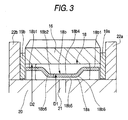
- Fig. 3 is a cross-sectional view showing the needle roller bearing of the planetary gear mechanism and its vicinities on an enlarged scale
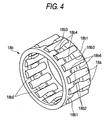
- Fig. 4 is an enlarged view of the needle roller bearing of Fig. 3.
- a sun gear (externally-toothed gear) 12 and a ring gear (internally-toothed gear) 14 are arranged in concentric relation to each other, and a plurality of planetary gears (externally-toothed gears) 16 are disposed between the sun gear 12 and the ring gear 14.
- the sun gear 12, the ring gear 14 and the planetary gears 16 are helical gears each having a tooth trace inclined relative to its axis.
- Each planetary gear 16 is rotatably supported on a planetary gear support shaft 20 through the needle roller bearing 18.
- An oil passageway 21 is formed in the planetary gear support shaft 20, and axially extends from a right end (Fig.
- each support shaft 20 extends in the axial direction in parallel relation to each other, and each support shaft 20 is connected and fixed at its opposite ends to right and left (in the drawings) planetary gear carriers 22a and 22b.
- the planetary gear carriers 22a and 22b are integrally interconnected by an interconnecting portion (not shown).
- a washer 19 is interposed between opposed side surfaces of each planetary gear 16 and each planetary gear carrier 22a, 22b.
- the sun gear 12 is fitted on a rotation shaft 14, and is connected to this rotation shaft 14 through axial splines so as to rotate therewith.
- the planetary gear carrier 22 is connected with a rotation shaft (not shown), and when this rotation shaft is rotated, the plurality of planetary gears 16 are revolved in a path between the sun gear 12 and the ring gear 14.
- the ring gear 14 is connected with a rotation shaft (not shown).
- the needle roller bearing 18 of this embodiment is interposed between the planetary gear 16 and the outside diameter surface (outer peripheral surface) of the planetary gear support shaft 20.
- This needle roller bearing 18 is of the cage-and-roller type, and comprises a plurality of needle rollers 18a, and a cage 18b positioning and holding these needle rollers 18a.
- a bore diameter surface (inner peripheral surface) of the planetary gear 16 serves as an outer ring raceway
- the outside diameter surface of the planetary gear support shaft 20 serves as an inner ring raceway
- an outside diameter surface (outer peripheral surface) of the cage 18b is guided by the bore diameter surface of the planetary gear 16.
- the cage 18b includes a pair of annular portions 18b1 interconnected by a plurality of pillar portions 18b2, and a plurality of pocket holes 18b3 holding the needle rollers 18a, respectively, each pocket hole 18b3 being formed between the two circumferentially-adjacent pillar portions 18b2.
- a pillar central portion 18b4 of each pillar portion 18b2 is bent radially inwardly such that the central portion of the cage 18b is reduced in diameter.
- Pillar opposite side portions 18b6 of the pillar portion 18b2 disposed respectively on opposite sides of the pillar central portion 18b4 in the axial direction are formed such that those portions of the cage 18b disposed respectively on the opposite sides of the central portion thereof are enlarged in diameter.
- the cage 18b has the pillar portions 18b2 of the above construction, and the pillar central portions 18b4 support those portions of the needle rollers 18a disposed radially inwardly of a pitch circle diameter of the row of needle rollers 18a, while the pillar opposite side portions 18b6 support those portions of the needle rollers 18a disposed radially outwardly of the pitch circle diameter of the row of needle rollers 18a, thereby holding the needle rollers 18a against withdrawal.
- the outside diameter surface of the cage 18b which has the largest outside diameter and serves as the outside diameter guide surface is the outside diameter surface of each annular portion 18bl.
- a surface treatment can be applied to the outside diameter surface of the cage 18b in order to decrease the degree of surface roughness thereof.
- a treatment layer (such as a friction-reducing layer, a lubrication-imparting layer, etc.) capable of reducing a sliding resistance developing during a sliding movement between the outside diameter surface of the cage 18b and the bore .diameter surface of the planetary gear 16 can be formed on the outside diameter surface of the cage 18b.
- the cage 18b instead of being formed into the above inverted M-shape, can be formed into a portal shape such that the outside diameter surface of the pillar portion 18b2 is constant in the axial direction, and the axially-central portion (that is, the pillar central portions 18b4) of the cage is enlarged in diameter at the bore diameter surface thereof to provide an annular recess 18b5 enabling the smooth supply of oil from the oil passageway 21.
- the outside diameter of this portal type cage 18b is uniform in the axial direction.
- an outside diameter dimension D1 of the cage 18b is set to the range of from 95% to 97% of an inner diameter dimension D2 of the planetary gear 16.
- the outside diameter dimension of the cage 18b set to the range from not smaller than 95% to not larger than 97% of the inner diameter dimension of the planetary gear 16
- the outside diameter dimension of the cage 1.8b in some cases, becomes less than 95% or larger than 97% of the inner diameter dimension of the planetary gear 16 because of a manufacturing error or the like.
- the outside diameter dimension D1 of the cage 18b is set to the proper range of from 95% to 97% of the inner diameter dimension D2 of the planetary gear 16, and therefore this sliding resistance developing between the outside diameter surface of the cage 18b and the bore diameter surface of the planetary gear 16 can be made small, and therefore abnormal wear and seizure of these sliding surfaces are suppressed.
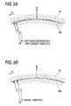
- Fig. 5A shows the case where the outside diameter dimension D1 of the cage is not smaller than 95% and not larger than 97% of the inner diameter dimension D2 of the planetary gear 16.
- Fig. 5B shows the case where the outside diameter dimension D1 of the cage is larger than 97% of the inner diameter dimension D2 of the planetary gear 16.
- the planetary gear 16 revolves at high speed in a direction of arrow A, and a centrifugal force acts on the cage 18b in a direction of arrow B.
- the cages 18b having their respective outside diameter dimension (D1) values, have the same weight.
- the outside diameter dimension D1 of the cage 18b is in the proper range of from 95% to 97% of the inner diameter dimension D2 of the planetary gear 16, and the proper dimensional difference between the outside diameter dimension D1 and the inner diameter dimension D2 is secured. Therefore, even when the centrifugal force acts on the cage 18b, so that this cage 18b is moved in the centrifugal force-acting direction, an area of contact between the cage 18b and the planetary gear 16 is reduced to a small value.
- the outside diameter dimension D1 of the cage 18b is more than 97% of the inner diameter dimension D2 of the planetary gear 16, and the dimensional difference between the outside diameter dimension D1 and the inner diameter dimension D2 is extremely small, and when the centrifugal force acts on the cage 18b to move this cage 18b in the centrifugal force-acting direction, the pressure of contact between the bore diameter surface of the planetary gear 16 and the outside diameter surface of the cage 18b, as well as the contact area therebetween, increases.
- the speed of revolution of a planetary gear 16 is 5892 r/min.
- the radius of revolution of the planetary gear 16 is 90 mm.
- a centrifugal acceleration of the planetary gear 16 is 3404G.
- the speed of rotation of the planetary gear 16 is 9896 r/min.
- Lubricating oil is ATF.
- the amount of the lubricating oil is 60 cc/min.
- the temperature of the lubricating oil is 120°C.
- the weight of a cage 18b is 5.0 g.
- a centrifugal force acting on the cage 18b is 171 N.
- the inner diameter of the planetary gear 16 is 24.562 mm.
- cages 18b having respective outside diameter dimensions of 23.3 mm, 23.6 mm, 23.8 mm, 24.1 mm and 24.3 mm, and it was confirmed whether abnormal wear and seizure had developed on the outside diameter surface of each cage 18b and the bore diameter surface of the planetary gear 16 for each cage 18b.
- two cages 18b were used for each of the outside diameter dimensions of 23.3 mm, 23.6 mm, 23.8 mm, 24.1 mm and 24.3 mm.
- the inner diameter dimension of the planetary gear 16 was kept to the constant value of 24.562 mm, while the outside diameter dimension of the cage 18b was changed.
- the centrifugal acceleration acting on the planetary gear 16 is 3000G or more
- the relation between the inner diameter dimension of the planetary gear 16 and the outside diameter dimension of the cage 18b in the above test can be expressed by the generalized formula in which the inner diameter dimension of the planetary gear 16 is represented in terms of 100%, while the outside diameter dimension of the cage 18b is represented in terms of a percentage (%) value of the inner diameter dimension of the planetary gear 16.
Landscapes
- Engineering & Computer Science (AREA)
- General Engineering & Computer Science (AREA)
- Mechanical Engineering (AREA)
- Rolling Contact Bearings (AREA)
- General Details Of Gearings (AREA)
Applications Claiming Priority (1)
| Application Number | Priority Date | Filing Date | Title |
|---|---|---|---|
| JP2006040709A JP2007218369A (ja) | 2006-02-17 | 2006-02-17 | 遊星歯車機構用ころ軸受 |
Publications (2)
| Publication Number | Publication Date |
|---|---|
| EP1820981A2 true EP1820981A2 (fr) | 2007-08-22 |
| EP1820981A3 EP1820981A3 (fr) | 2010-12-29 |
Family
ID=38006213
Family Applications (1)
| Application Number | Title | Priority Date | Filing Date |
|---|---|---|---|
| EP07003147A Withdrawn EP1820981A3 (fr) | 2006-02-17 | 2007-02-14 | Roulement à rouleaux pour mécanisme d'un engrenage planétaire |
Country Status (3)
| Country | Link |
|---|---|
| US (1) | US20070202986A1 (fr) |
| EP (1) | EP1820981A3 (fr) |
| JP (1) | JP2007218369A (fr) |
Cited By (1)
| Publication number | Priority date | Publication date | Assignee | Title |
|---|---|---|---|---|
| WO2012093010A1 (fr) * | 2011-01-03 | 2012-07-12 | Robert Bosch Gmbh | Transmission à trains épicycloïdaux pour une machine-outil |
Families Citing this family (10)
| Publication number | Priority date | Publication date | Assignee | Title |
|---|---|---|---|---|
| US7730869B2 (en) * | 2007-04-13 | 2010-06-08 | Yan Li | Housing wheel engine |
| EP2215357B1 (fr) * | 2007-10-22 | 2011-12-07 | Vestas Wind Systems A/S | Étage de train épicycloïdal pour boîte d'éolienne, boîte de vitesse d'éolienne et éolienne |
| ES2364319T3 (es) * | 2007-12-20 | 2011-08-31 | Vestas Wind Systems A/S | Etapa de engranajes epicíclicos para una caja de engranajes de turbina eólica, caja de engranajes de turbina eólica y turbina eólica. |
| JP5169719B2 (ja) * | 2008-10-17 | 2013-03-27 | 株式会社ジェイテクト | 遊星歯車機構のころ軸受 |
| DE102009024027A1 (de) * | 2009-06-02 | 2010-12-09 | Schaeffler Technologies Gmbh & Co. Kg | Maschinenelement |
| KR101009742B1 (ko) * | 2010-10-29 | 2011-01-19 | 주식회사 세진아이지비 | 동력전달장치 |
| US10641332B2 (en) * | 2016-12-06 | 2020-05-05 | General Electric Company | Roller element bearing with preloaded hydrodynamic cage guides |
| US9927021B1 (en) * | 2016-12-29 | 2018-03-27 | Zf Friedrichshafen Ag | Planet carrier for a planetary gear set |
| US10428929B2 (en) * | 2018-02-05 | 2019-10-01 | Schaeffler Technologies AG & Co. KG | Composite planetary staking pin with lubrication feed feature |
| JP7114976B2 (ja) * | 2018-03-27 | 2022-08-09 | 株式会社ジェイテクト | ケージアンドローラ |
Family Cites Families (12)
| Publication number | Priority date | Publication date | Assignee | Title |
|---|---|---|---|---|
| US3261234A (en) * | 1963-11-06 | 1966-07-19 | Skf Ind Inc | Transmission bearing |
| US3821908A (en) * | 1972-12-12 | 1974-07-02 | Allis Chalmers | Retainer for planet pinion shaft |
| JP2527161Y2 (ja) * | 1989-03-28 | 1997-02-26 | ジャトコ 株式会社 | 遊星歯車装置のキャリア組立体 |
| US5255985A (en) * | 1992-11-17 | 1993-10-26 | The Torrington Company | Roller bearing sigma cage |
| CN1068388C (zh) * | 1994-07-30 | 2001-07-11 | 株式会社理研 | 滑动部件 |
| DE19932447B4 (de) * | 1998-07-10 | 2004-03-11 | Nsk Ltd. | Zylinderrollenlager |
| JP4096689B2 (ja) * | 2002-10-10 | 2008-06-04 | 株式会社ジェイテクト | 二つ割り保持器 |
| JP4165206B2 (ja) * | 2002-12-24 | 2008-10-15 | 株式会社ジェイテクト | ギヤインナ用針状ころ軸受 |
| JP2005180501A (ja) * | 2003-12-17 | 2005-07-07 | Koyo Seiko Co Ltd | ころ軸受およびこれを備えた動力伝達装置 |
| JP2005214390A (ja) * | 2004-02-02 | 2005-08-11 | Nsk Ltd | ニードル軸受、遊星歯車機構及びピニオンシャフト |
| JP2006144839A (ja) * | 2004-11-17 | 2006-06-08 | Ntn Corp | ころ軸受 |
| US7419307B2 (en) * | 2005-09-30 | 2008-09-02 | Caterpillar Inc. | Rotary machine |
-
2006
- 2006-02-17 JP JP2006040709A patent/JP2007218369A/ja active Pending
-
2007
- 2007-02-14 EP EP07003147A patent/EP1820981A3/fr not_active Withdrawn
- 2007-02-15 US US11/706,432 patent/US20070202986A1/en not_active Abandoned
Cited By (2)
| Publication number | Priority date | Publication date | Assignee | Title |
|---|---|---|---|---|
| WO2012093010A1 (fr) * | 2011-01-03 | 2012-07-12 | Robert Bosch Gmbh | Transmission à trains épicycloïdaux pour une machine-outil |
| CN107053060A (zh) * | 2011-01-03 | 2017-08-18 | 罗伯特·博世有限公司 | 用于工具机的行星齿轮传动装置 |
Also Published As
| Publication number | Publication date |
|---|---|
| JP2007218369A (ja) | 2007-08-30 |
| US20070202986A1 (en) | 2007-08-30 |
| EP1820981A3 (fr) | 2010-12-29 |
Similar Documents
| Publication | Publication Date | Title |
|---|---|---|
| EP1820981A2 (fr) | Roulement à rouleaux pour mécanisme d'un engrenage planétaire | |
| EP2447557B1 (fr) | Support en résine synthétique pour roulement à billes à gorge profonde; roulement à billes à gorge profonde; et dispositif de support d'engrenage | |
| US5852947A (en) | Main shaft gear mechanism in a transmission for a vehicle | |
| US20080268997A1 (en) | Lubrication path in a planetary gear unit for a transmission | |
| US7513043B2 (en) | Support structure carrying thrust load of transmission, method of manufacturing thereof and thrust needle roller bearing | |
| US8545358B2 (en) | Gear transmission | |
| US6644138B2 (en) | Variable speed gear transmission | |
| EP3051160A1 (fr) | Roulement à billes à rainures profondes | |
| US20060065488A1 (en) | Lubricating structure of planetary gear mechanism | |
| JP4196569B2 (ja) | 遊星歯車機構 | |
| JP2010255645A (ja) | ラジアルニードル軸受 | |
| JP2005214390A (ja) | ニードル軸受、遊星歯車機構及びピニオンシャフト | |
| JP2008303992A (ja) | ラジアル針状ころ軸受 | |
| JP2010255778A (ja) | ラジアルニードル軸受 | |
| JP2009115300A (ja) | 針状ころ軸受 | |
| US6929578B1 (en) | Planetary gear carrier assembly | |
| JP2009287772A (ja) | 針状ころ軸受 | |
| US20050064979A1 (en) | Bevel gear transmission | |
| JP2005076810A (ja) | 針状ころ軸受用の保持器及び針状ころ軸受 | |
| US10428929B2 (en) | Composite planetary staking pin with lubrication feed feature | |
| JP2005214392A (ja) | 遊星歯車機構及びギヤ側レース | |
| KR20050025470A (ko) | 수동 변속기의 오일 공급 구조 | |
| CN220850595U (zh) | 一种传动机构及内变速花鼓 | |
| JP5421484B2 (ja) | ワンウェイクラッチ | |
| JP2007024086A (ja) | 軸受装置 |
Legal Events
| Date | Code | Title | Description |
|---|---|---|---|
| PUAI | Public reference made under article 153(3) epc to a published international application that has entered the european phase |
Free format text: ORIGINAL CODE: 0009012 |
|
| AK | Designated contracting states |
Kind code of ref document: A2 Designated state(s): AT BE BG CH CY CZ DE DK EE ES FI FR GB GR HU IE IS IT LI LT LU LV MC NL PL PT RO SE SI SK TR |
|
| AX | Request for extension of the european patent |
Extension state: AL BA HR MK YU |
|
| PUAL | Search report despatched |
Free format text: ORIGINAL CODE: 0009013 |
|
| AK | Designated contracting states |
Kind code of ref document: A3 Designated state(s): AT BE BG CH CY CZ DE DK EE ES FI FR GB GR HU IE IS IT LI LT LU LV MC NL PL PT RO SE SI SK TR |
|
| AX | Request for extension of the european patent |
Extension state: AL BA HR MK RS |
|
| AKY | No designation fees paid | ||
| REG | Reference to a national code |
Ref country code: DE Ref legal event code: R108 |
|
| REG | Reference to a national code |
Ref country code: DE Ref legal event code: R108 Effective date: 20110907 |
|
| STAA | Information on the status of an ep patent application or granted ep patent |
Free format text: STATUS: THE APPLICATION IS DEEMED TO BE WITHDRAWN |
|
| 18D | Application deemed to be withdrawn |
Effective date: 20110630 |