EP1820983A1 - Bewegungsführungsvorrichtung, tischvorrichtung und dämpfungsvorrichtung für bewegungsführungsvorrichtung - Google Patents
Bewegungsführungsvorrichtung, tischvorrichtung und dämpfungsvorrichtung für bewegungsführungsvorrichtung Download PDFInfo
- Publication number
- EP1820983A1 EP1820983A1 EP05800466A EP05800466A EP1820983A1 EP 1820983 A1 EP1820983 A1 EP 1820983A1 EP 05800466 A EP05800466 A EP 05800466A EP 05800466 A EP05800466 A EP 05800466A EP 1820983 A1 EP1820983 A1 EP 1820983A1
- Authority
- EP
- European Patent Office
- Prior art keywords
- oil
- rolling
- raceway
- moving
- plates
- Prior art date
- Legal status (The legal status is an assumption and is not a legal conclusion. Google has not performed a legal analysis and makes no representation as to the accuracy of the status listed.)
- Granted
Links
Images








Classifications
-
- F—MECHANICAL ENGINEERING; LIGHTING; HEATING; WEAPONS; BLASTING
- F16—ENGINEERING ELEMENTS AND UNITS; GENERAL MEASURES FOR PRODUCING AND MAINTAINING EFFECTIVE FUNCTIONING OF MACHINES OR INSTALLATIONS; THERMAL INSULATION IN GENERAL
- F16C—SHAFTS; FLEXIBLE SHAFTS; ELEMENTS OR CRANKSHAFT MECHANISMS; ROTARY BODIES OTHER THAN GEARING ELEMENTS; BEARINGS
- F16C29/00—Bearings for parts moving only linearly
- F16C29/04—Ball or roller bearings
- F16C29/06—Ball or roller bearings in which the rolling bodies circulate partly without carrying load
-
- F—MECHANICAL ENGINEERING; LIGHTING; HEATING; WEAPONS; BLASTING
- F16—ENGINEERING ELEMENTS AND UNITS; GENERAL MEASURES FOR PRODUCING AND MAINTAINING EFFECTIVE FUNCTIONING OF MACHINES OR INSTALLATIONS; THERMAL INSULATION IN GENERAL
- F16C—SHAFTS; FLEXIBLE SHAFTS; ELEMENTS OR CRANKSHAFT MECHANISMS; ROTARY BODIES OTHER THAN GEARING ELEMENTS; BEARINGS
- F16C29/00—Bearings for parts moving only linearly
- F16C29/08—Arrangements for covering or protecting the ways
- F16C29/084—Arrangements for covering or protecting the ways fixed to the carriage or bearing body movable along the guide rail or track
- F16C29/086—Seals being essentially U-shaped, e.g. for a U-shaped carriage
-
- F—MECHANICAL ENGINEERING; LIGHTING; HEATING; WEAPONS; BLASTING
- F16—ENGINEERING ELEMENTS AND UNITS; GENERAL MEASURES FOR PRODUCING AND MAINTAINING EFFECTIVE FUNCTIONING OF MACHINES OR INSTALLATIONS; THERMAL INSULATION IN GENERAL
- F16C—SHAFTS; FLEXIBLE SHAFTS; ELEMENTS OR CRANKSHAFT MECHANISMS; ROTARY BODIES OTHER THAN GEARING ELEMENTS; BEARINGS
- F16C29/00—Bearings for parts moving only linearly
-
- F—MECHANICAL ENGINEERING; LIGHTING; HEATING; WEAPONS; BLASTING
- F16—ENGINEERING ELEMENTS AND UNITS; GENERAL MEASURES FOR PRODUCING AND MAINTAINING EFFECTIVE FUNCTIONING OF MACHINES OR INSTALLATIONS; THERMAL INSULATION IN GENERAL
- F16C—SHAFTS; FLEXIBLE SHAFTS; ELEMENTS OR CRANKSHAFT MECHANISMS; ROTARY BODIES OTHER THAN GEARING ELEMENTS; BEARINGS
- F16C29/00—Bearings for parts moving only linearly
- F16C29/04—Ball or roller bearings
- F16C29/06—Ball or roller bearings in which the rolling bodies circulate partly without carrying load
- F16C29/0633—Ball or roller bearings in which the rolling bodies circulate partly without carrying load with a bearing body defining a U-shaped carriage, i.e. surrounding a guide rail or track on three sides
- F16C29/0635—Ball or roller bearings in which the rolling bodies circulate partly without carrying load with a bearing body defining a U-shaped carriage, i.e. surrounding a guide rail or track on three sides whereby the return paths are provided as bores in a main body of the U-shaped carriage, e.g. the main body of the U-shaped carriage is a single part with end caps provided at each end
- F16C29/0638—Ball or roller bearings in which the rolling bodies circulate partly without carrying load with a bearing body defining a U-shaped carriage, i.e. surrounding a guide rail or track on three sides whereby the return paths are provided as bores in a main body of the U-shaped carriage, e.g. the main body of the U-shaped carriage is a single part with end caps provided at each end with balls
- F16C29/0642—Ball or roller bearings in which the rolling bodies circulate partly without carrying load with a bearing body defining a U-shaped carriage, i.e. surrounding a guide rail or track on three sides whereby the return paths are provided as bores in a main body of the U-shaped carriage, e.g. the main body of the U-shaped carriage is a single part with end caps provided at each end with balls with four rows of balls
- F16C29/0647—Ball or roller bearings in which the rolling bodies circulate partly without carrying load with a bearing body defining a U-shaped carriage, i.e. surrounding a guide rail or track on three sides whereby the return paths are provided as bores in a main body of the U-shaped carriage, e.g. the main body of the U-shaped carriage is a single part with end caps provided at each end with balls with four rows of balls with load directions in X-arrangement
-
- F—MECHANICAL ENGINEERING; LIGHTING; HEATING; WEAPONS; BLASTING
- F16—ENGINEERING ELEMENTS AND UNITS; GENERAL MEASURES FOR PRODUCING AND MAINTAINING EFFECTIVE FUNCTIONING OF MACHINES OR INSTALLATIONS; THERMAL INSULATION IN GENERAL
- F16C—SHAFTS; FLEXIBLE SHAFTS; ELEMENTS OR CRANKSHAFT MECHANISMS; ROTARY BODIES OTHER THAN GEARING ELEMENTS; BEARINGS
- F16C29/00—Bearings for parts moving only linearly
- F16C29/08—Arrangements for covering or protecting the ways
- F16C29/084—Arrangements for covering or protecting the ways fixed to the carriage or bearing body movable along the guide rail or track
- F16C29/088—Seals extending in the longitudinal direction of the carriage or bearing body
Definitions
- the present invention relates to motion guide devices, such as liner guides, ball splines, and ball screws, in which there are a raceway member, a moving member and rolling members, such as balls and rollers, intervening between the raceway member and the moving member.
- rolling-guide type of motion guide devices Like a table making a linear movement on a frame of a machine, rolling-guide type of motion guide devices have now been put to use, in which rolling elements, including balls or rollers, are arranged in a guide portion subjected to a liner movement, are used to provide a guide function with the aid of rolling motions of the rolling elements.
- This rolling-guide type of motion guide device is equipped with a raceway rail forming a track for motions of a moving member, a moving block moving relatively to the raceway rail, and rolling elements disposed to intervene between the raceway rail and the moving block.
- the rolling guide Compared to sliding guide, the rolling guide has various advantages, such as extremely low friction resistance and being operated even in a condition there is no play at all by being pressurized. However, at the same time, the rolling guide cannot generate a damping force like friction resistance caused in the sliding guide, so that there is a disadvantage that vibration, once caused, is difficult to be damped. When a moving member is moved to a target position and then stopped thereat, the vibration will occur due to the inertia of the moving member and, even during movement of the moving member, the vibration may occur.
- the damping technique by attaching the dynamic damper to the moving block is confronted with a difficulty that the device is made larger in size.
- the weight and elastic member of the dynamic damper needs to be designed on vibration of the moving member.
- the present inventors have adopted a damping structure in which, in a motion guide device performing guide for a liner or curved movement, oil is filled in a gap between a moving member and a raceway member and the viscosity resistance of the oil is utilized to give the motion guide device a damping characteristic.
- the invention according to claim 1 is characterized in that the device comprises a raceway member (1) having a rolling-element rolling part (1a); a moving member (2) having a loaded rolling-element rolling part (2a) facing the rolling-element rolling part (1a) and being allowed to make a linear or curved movement relatively to the raceway member (1); a plurality of rolling elements (3) intervening between the rolling-element rolling part (1a) of the raceway member (1) and the loaded rolling-element rolling part (2a) of the moving part (2); and a layer of oil filled in a gap (16) between the raceway member (1) and the moving member (2) such that the layer of oil contacts the raceway member (1) and the moving member (2), wherein viscosity resistance of the oil is utilized to apply a braking force to the moving member (2) or the raceway member (1) in proportion to a speed.
- the invention according to claim 2 which is based on the motion guide device according to claim 1, is characterized in that the moving member (2) comprise a moving block (4) on which the rolling-element rolling part (2a) is formed, and a damping member (5, 6) attached to the moving block, wherein the layer of oil is filled in a gap between the damping member (5, 6) and the raceway member (1).
- the invention according to claim 3, which is based on the motion guide device according to claim 2, is characterized in that the damping member (5, 6) has an oil supply passage (15) supplying the oil to the gap (16) and the oil flows out from the gap (16).
- the invention according to claim 4, which is based on the motion guide device according to claim 2 or 3, is characterized in that the damping member (5, 6) has a surface to which the layer of oil is contacted, the surface being formed to be concavo-convex.
- the invention according to claim 5, which is based on the motion guide device according to claim 2, is characterized in that the damping member (5) includes an end damping member (5) attached to an end face of the moving member (2), the end face being located in a movement direction of the moving member, the end damping member (5) has a plurality of first thin plates (9) and a plurality of second thin plates (10), the first and second plates being laminated on one another alternately between the first and second plates, the first plates (9) and the second plates (10) have an opening (9a, 10a) formed therein to be consistent in shape with the raceway member (1), and a gap ( ⁇ ) between the second plates (10) and the raceway member (1) is larger than a gap ( ⁇ ) between the first plates (9) and the raceway member (1) so that the end damping member (5) has a surface contacted by the layer of oil and shaped to become the concavo-convex surface in a condition where the first plates (9) and the second plates (10) are laminated.
- the invention according to claim 6, which is based on the motion guide device according to claim 5, is characterized in that the second plates (10) have a slit (10c) formed therein for supplying oil to the gap (16) between the end damping member (5) and the raceway member (1), and the first plates (9) and the second plates (10) have an oil supply hole (9b, 10b) formed therein for supplying the oil to the slit (9c) formed in the second plates (9) in the condition where the first plates (9) and the second plates (10) are laminated.
- the invention according to claim 7, which is based on the motion guide device according to claim 2, is characterized in that the moving block (4) has a central part (4a) facing an upper surface of the raceway member (1) and a stem part (4b) facing a side surface of the raceway member (1), the moving block being formed into a saddle shape as a whole, the damping member (6, 21, 24, 26) includes a side damping member (6, 21, 24, 26) attached to the stem portion (4b) of the moving block (4), and the layer of oil is formed between the side damping member (6, 21, 24, 26) and the raceway member (1).
- the invention according to claim 8, which is based on the motion guide device according to claim 7, is characterized in that the side damping member (21) has a plurality of grooves (23) each extending a direction intersecting a movement direction of the moving member (2).
- the invention according to claim 9, which is based on the motion guide device according to claim 7, is characterized in that the side damping member (24) has a plurality of grooves (29) each extending along a movement direction of the moving member (2).
- the invention according to claim 10 is a table apparatus comprising a motion guide device comprising a raceway member (1) having a rolling-element rolling part (1a), a moving block (2) having a loaded rolling-element rolling part (2a) facing the rolling-element rolling part (1a) and being allowed to make a linear or curved movement relatively to the raceway member (1), and a plurality of rolling elements (3) intervening between the rolling-element rolling part (1a) of the raceway member (1) and the loaded rolling-element rolling part (2a) of the moving part (2); a table (31) attached to the moving member (2) of the motion guide device; and a damping member (32) moving, together with the table (31), along the raceway member (1); and a layer of oil filled in a gap between the raceway member (1) and the damping member (32) such that the layer of oil contacts the raceway member (1) and the damping member (32), wherein viscosity resistance of the oil is utilized to apply a braking force to the table (32) in proportion to a speed.
- the invention according to claim 11 is a damping method for a motion guide device comprising a raceway member (1) having a rolling-element rolling part (1a), a moving block (2) having a loaded rolling-element rolling part (2a) facing the rolling-element rolling part (1a) and being allowed to make a linear or curved movement relatively to the raceway member (1), and a plurality of rolling elements (3) intervening between the rolling-element rolling part (1a) of the raceway member (1) and the loaded rolling-element rolling part (2a) of the moving part (2), characterized in that the method comprising: filling a layer of oil into a gap between the raceway member (1) and the moving member (2) such that the layer of oil contacts the raceway member (1) and the moving member (2); and viscosity resistance of the oil is utilized to apply a braking force to the moving member (2) or the raceway member (1) in proportion to a speed.
- the viscosity resistance of the layer of the oil filled in the gap between the raceway member and the moving member gives the motion guide device a damping characteristic. Since the braking power is in proportion to the movement speed of the moving member, the braking power caused when the device starts remains to be smaller, while the braking power becomes higher with an increase in the movement speed of the moving member. Accordingly, for moving the moving member with the help of a motor, for instance, the braking force can be reduced so that a load applied to the motor is reduced. Meanwhile when the moving member stops and is about to vibrate, the braking force can be made larger to suppress and damp the vibration smoothly.
- the device can be used semi-permanently as a device with the damping function. Hence it is avoidable that the disadvantage that damping the vibration is weakened as the time goes by, which is seen in contact seals.
- the damping member is arranged as a member which is different from the moving block, so that it is easier to make the gap between the damping member and the raceway member. Because the viscosity resistance of the oil becomes larger as the oil layer is thinner, a larger braking force can be obtained by making the gap between the damping member and the raceway member thinner.
- the oil supply passage is formed for supplying oil to the gap between the damping member and the raceway member, whereby the oil can be filled into the gap even when the oil flows out of the gap.
- the concavo-convex shape of the surface of the damping member gives the oil sticking to the damping member.
- the damping member has an improved performance for retaining the oil, thereby reducing the amount of oil flowing out of the gap.
- the surface of the damping member which contacts the layer of oil is made flat, there is no means for giving sticking to the damping member, the oil retaining performance of the damping member is lessened.
- the end damping member with a concavo-convex surface to contact the layer of oil.
- the oil can be retained by the end damping member.
- the oil can be filled into the gap between the end damping member and the raceway member.
- the slit is formed in the second plates with the gap from the raceway member is larger, so that it is easier to fill the oil into the gap between the end damping member and the raceway member.
- the slit is formed every two plates, which allows the oil to be filled in the entire gap with ease. And, compared to the structure in which the slit is formed in both the first and second plates, the amount of oil can be suppressed, with the oil still supplied at an appropriate amount.
- the layer of oil may be located between the side damping member and the raceway member.
- the grooves are formed on the side damping member to extend in the direction intersecting the movement directions of the moving member. Therefore, when the side damping member is moved relatively to the moving member, the oil can still be retained by the side damping member.
- the grooves are formed on the side damping member to extend in the movement directions of the moving member. This prevents the oil form flowing out of the side damping member in the direction (for example, downward direction) intersecting the movement directions of the moving member.
- the viscosity resistance of the layer of the oil filled in the gap between the raceway member and the damping member give the table a damping characteristic.
- the viscosity resistance of the layer of the oil filled in the gap between the raceway member and the moving member gives the motion guide device a damping characteristic. Since the braking power is in proportion to the movement speed of the moving member, the braking power caused when the device starts remains to be smaller, while the braking power becomes higher with an increase in the movement speed of the table. Accordingly, for moving the table with the help of a motor, for instance, the braking force can be reduced so that a load applied to the motor is reduced.
- the braking force can be made larger to suppress and damp the vibration smoothly.
- the device can be used semi-permanently as a device with the damping function. Hence it is avoidable that the disadvantage that damping the vibration is weakened as the time goes by, which is seen in contact seals.
- Figs. 1-4 show a motion guide device according to an embodiment of the present invention.
- Fig. 1 is a perspective view showing the motion guide device
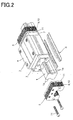
- Fig. 2 is a disassembled perspective view showing the motion guide device
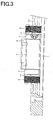
- Fig. 3 is a side view
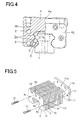
- Fig. 4 is a frontal view (with a view partially sectioned).
- the motion guide device according to the present embodiment is called a liner guide and is provided with a raceway rail 1 extending linearly and serving as a raceway member, and a moving member 2 movably assembled with the raceway rail 1 with a large number of balls 3 serving as rolling elements therebetween.
- each ball rolling groove 1a On both right and left side surfaces of the raceway rail 1, there formed ball rolling grooves 1a, serving as rolling-element rolling portion, extending a longitudinal direction thereof.
- Each ball rolling groove 1a has an arch-shaped section of which curvature is slightly larger than the diameter of each ball 3.
- two grooves are formed at upper and lower positions thereof, so that four ball rolling grooves 1a are formed in total.
- the number of grooves and arrangements of the grooves can be set in various ways depending on factors such as weight to be loaded.
- the moving member 2 is composed of a moving block 4 on which a ball circulation passage including a loaded ball rolling groove 2a facing a ball rolling groove 1a and damping members 5 and 6 attached to the moving block 4.
- the moving block 4 is formed to have a saddle shape as a whole and has a central part 4a facing an upper surface of the raceway rail 1 and stem parts 4b respectively extending downward from the right and left both sides of the central part 4a and facing side surfaces of the raceway rail 1.
- the plurality of balls 3 are present for intervention therebetween.
- the balls 3 make a rolling movement along the loaded ball rolling passage with being weighed.
- the balls 3 which have rolled and reached one end of the loaded ball rolling passage of the moving block 4 enters the U-shaped direction changing passage formed in each end plate 7 (refer to Figs. 1 and 2).
- a ball circulation passage is composed in a circuit form by a combination of the liner loaded ball rolling passage, the U-shaped direction changing passages, and the liner non-loaded ball return passage 8.
- each end damping member 5 is composed of a plurality of first thin plates 9 and a plurality of second thin plates 10, which are laminated on one another alternately between the first and second plates, and a holding plate 11 to which each of the first and second plates 9 and 10 is attached.
- the end damping member 5 has an opening of which contour is in accord with the outer shape of the raceway rail 1. With no contact with the raceway rail 1, the end damping members 5 make a gap between the raceway rail 1 and the moving block 4 as small as possible.
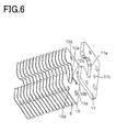
- Figs. 5 and 6 show a disassembled perspective view of each end damping member 5.
- Fig. 5 shows a disassembled perspective view of a combination of the first plates 9, the second plates 10, and the holding plate 11, while Fig. 6 is a disassembled perspective view obtained by flipping the end damping member 5 shown in Fig. 5.
- the first plates 9 are manufactured by stamping a thin metal plate such as stainless steel.
- Each of the first plates 9 is shaped into an approximately rectangular form and has a central part on a one side thereof, where the central part is formed to have an opening 9a of which shape is consistent with the contour of sections of the raceway rail 1. Though detailed later, the shape of the opening 9a is slightly larger than the sectional contour of the raceway rail 1.
- An oil supply hole 9b for supplying oil to a gap between each end damping member 5 and the raceway rail 1 is formed at a position of each of the first plates 9, the position being oppositely shifted from the opening 9a.
- through-holes 9c are formed therethrough which allow screws 13 or other elements to pass through for attaching both the first and second plates 9 and 10 to the holding plate 11.
- through-holes 9d are formed therethrough which allow screws 14 (refer to Fig. 2) or other elements to pass through for attaching each end damping member 5 to the moving block 4.
- a triangular notch 9f is formed on the surface of a side of each of the first plates 9.
- Each of the second plates 10 is also formed into an approximately rectangular form and has a central part on a one side thereof, where the central part is formed to have an opening 10a of which shape is consistent with the contour of sections of the raceway rail 1. Though detailed later, the openings 10a of the second plates 10 are slightly larger in contours than the openings 9a of the first plates 9. Accordingly, laminating the first and second plates 9 and 10 alternately one on another creates a concavo-convex shape along part of the opening portion.
- This concavo-convex shape consists of concavo rows and convex rows and those concavo and convex rows extend in a direction intersecting movement directions of the moving block (in the present embodiment, those concavo and convex parts extend in a direction perpendicular to the movement directions).
- An oil supply hole 10b for supplying oil to a gap between each end damping member 5 and the raceway rail 1 is formed at a position of each of the second plates 10, the position being oppositely shifted from the opening 10a.
- a slit 10 is formed to extend from the oil supply hole 10b to the opening 10a.
- This slit 10c functions as a passage through which the oil is supplied to the gap between the end damping member 5 and the raceway rail 1.
- through-holes 10d are also formed therethrough which allow the screw 13 or other elements to pass through.
- the second plates are also manufactured by stamping, for example, a thin metal plate.
- a triangular notch 10f is formed so as to be shifted from that of each of the first plates 9 in the longitudinal direction. This is for drawing the line between the first and second plates 9 and 10 from its external appearance after assembling.
- laser beam machining or wire electric discharge machining can be used for the production, whereby the first and second plates 9 and 10 are improved in their dimensional accuracy.
- each of the end damping members 5 has a number of concavo-convex shapes
- the first and second plates 9 and 10 have a certain degree of thickness.
- the first and second plates 9 and 10 are produced to have a thickness of 0.2 mm or thereabouts, for instance.
- various thickness amounts other than the above may be available depending on factors including the size of the moving block 4.
- the holding plate 11 is made thicker than the first and second plates 9 and 10.
- This holding plate 11 has also an opening 11a which is consistent in shape with the raceway rail 1.
- a oil circulation hole 11b communicating with the oil supply holes 9b and 10b is formed therethrough.
- female screw portions 11c are formed to be engageable with the screws 13.
- An assembling jig is used such that the first and second plates 9 and 10 and the holding plate 11 are pushed to this assembling jig for positioning, and the screws 13 are applied to combine those plates.
- Fig. 7 shows each end damping member which is laminated.
- the second plates 10 have the openings 10a slightly larger in contour size than the openings 9a of the first plates 9.
- a gap ⁇ between the second plates 10 and the raceway rail 1 is greater than a gap ⁇ between the first plates 9 and the raceway rail 1, whereby as described before, there are formed a concave-convex gap by the mutually faced surfaces between the plates 9, 10 and the raceway rail 1.
- the gap ⁇ between a portion of the first plates 9 which is the closest to the raceway rail 1 and the raceway rail 1 is set to 0.25 mm or less.
- the gap is set to some 0.05 to 0.25 mm.
- the raceway rail 1 involves a tolerance in its processing, setting the gap to a too small amount may cause a contact between the end damping members 5 and the raceway rail 1.
- the gap ⁇ is set to some 0.02 to 0.25 mm, preferably to some 0.05 to 0.15 mm.
- a difference ⁇ in height (step) between the first plates 9 and the second plates 10 is approximately equal to the thicknesses of the first and second plates 9 and 10, and for example set to some 0.2 mm.
- larger contact areas will cause the gap ⁇ between the second plates 10 and the raceway rail 1 to be larger, thus making the viscosity resistance smaller.
- the difference ⁇ between the heights should be decided depending on those mutually conflicting factors. Of course this difference will not be limited to 0.2 mm.
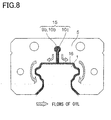
- Figs. 8 and 9 show flows of the oil in each of the end damping members 5.
- the oil supply holes 9b and 10b of the first and second plates 9 and 10 and the slits 10c of the second plates 10 compose an oil supply passage 15.
- the oil drops from the oil supply holes 9b and 10b and flows into a gap 16 formed between each end damping members 5 and the raceway rail 1 via the slits 10c of the second plates 10.
- arranging the oil supply passage 15 allows the gap 16 between each end damping members 5 and the raceway rail 1 to be filled with the oil all the time.
- the gap ⁇ between the second plates 10 and the raceway rail 1 is larger than the gap ⁇ between the first plates 9 and the raceway rail 1.
- the oil is easier to flow into the gap between the second plates 10 and the raceway rail 1, whereby the oil can readily be filled in the gaps 16 between the end damping members 5 and the raceway rail 1.
- the slits 10c are located every two plates, the oil is easier to spread over the gaps16, and in comparison with the case where the slits 10c are formed every plate, the amount of oil being supplied can be reduced to have the oil supplied at its appropriate amount.
- the end damping members 5 attached to the moving block 4 move without coming into contact with the raceway rail 1.
- the gap 16 between the inner side of each damping member 5 and the raceway rail 1 is filled with the layer of oil.
- the resistance of viscosity of the oil is caused which results in a braking force.
- the viscosity resistance of the oil damps vibration caused at the moving member 2.
- the viscosity resistance of the oil is in proportion of the moving speed of the moving member 2, with the result that the viscosity resistance caused when the moving member begins moving remains to be smaller, but becomes higher with increasing the moving speed of the moving member 2.
- a load to the motor can be reduced thanks to a smaller viscosity resistance.
- the vibration is suppressed and damped quickly thanks to a larger viscosity resistance.
- the gaps 16 between the respective end damping members 5 and the raceway rail 1 is formed to have the highly thin thickness and to the concavo-convex contact surface to the oil, the oil is difficult to flow out of the gaps 16. Besides it, using an oil having a higher kinetic viscosity for gaining a higher viscosity resistance makes it further difficult that the oil flows out of the gaps 16. However, being not sealed completely, the oil flows out of the gaps 16 at least little by little.
- the oil supplied to the gaps 16 is also applied to the raceway rail 1.
- a system supplying the gaps 16 with the oil resembles a compulsory oil-supply system compulsorily supplying lubricant to the raceway rail 1.
- the lubricant such as grease
- using lubricant whose kinetic viscosity is as high as 10 to 500 provides a higher viscosity resistance.
- the moving block 4 may have oil passages to be linked with the oil supply passages of the end damping members 5 and the oil passages may have loop-like connections with the pipe 12 (refer to Fig. 1) attached to the oil supply holes 9b and 10b of the end damping members 5 so that oil can be circulated through the loop passage.
- the circulation of the oil enables heat accumulated in the moving block 4 to escape outside through heat exchange thus providing a cooling effect. Even in this case, the oil flows outside of the gaps 16 in dribs.
- the oil flowed out of the gaps 16 may be collected or may not be collected. In such a case where the oil is given the function of coolant, it is necessary to additionally arrange a seal to prevent the coolant from coming in the moving block 4.
- Figs. 10 and 11 show a side damping member 6.
- the moving block 4 is formed to have a saddle shape as a whole and has the central part 4a facing the upper surface of the raceway rail 1 and the stem parts 4b respectively facing the side surfaces of the raceway rail 1.
- each side damping member 6, which extends in the movement directions of the moving block 4 is attached to the lower end of each stem part 4b.
- Each of the side damping members 6 has a protruding part 6b whose outer contour is consistent with the outer shape of the raceway rail 1 so that a gap 19 between each side damping member 6 and the raceway rail 1 becomes narrow.
- the gap 19 is set as its width to 0.05 to 0.25 mm, for instance.
- the protruding part 6b has a flat surface 6c facing the raceway rail 1.
- This gap 19 is filled with a layer of oil supplied through a not-shown oil supply passage. Thanks to the viscosity resistance of the oil layer that intervenes between each side damping member 6 and the raceway rail 1, the vibration can be damped.
- the side damping members 6 function as means for preventing the balls 3 from dropping out of the moving block 4, when the moving block 4 is removed from the raceway rail 1. To give this function to the side damping members 6, a distance between an upper end 6a and the side damping member 6 and an upper end 18 of the loaded ball rolling groove 2a is made smaller than the diameter of each ball 3.
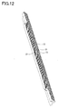
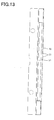
- Figs. 12 and 13 show another example of the side damping member.
- This example provides a side damping member 21, which has a surface 22 contacting a layer of oil. On the surface 22, there are formed a plurality of grooves 23 respectively extending in parallel with each other along a direction perpendicular to the movement directions of the moving member 2.
- This side damping member 21 moves together with the moving member 2 in the movement directions of the moving member 2.
- Providing the side damping member 21 with the plural grooves 23 formed thereon to extend in the direction perpendicular to the movement directions of the moving member 2 enables the side damping member 21 to have an improved capability of sustaining the oil.
- Figs. 14 and 15 show another example of the side damping member.
- This example provides a side damping member 24, which has a surface 25 contacting a layer of oil.
- This exemplified side damping member 24 has the plural grooves extending along the movement directions of the moving member 2, whereby it is possible to prevent the oil from flowing out of the side damping member 24 in the direction (for example, a downward direction) perpendicular to the movement directions of the moving member 2.
- the plural grooves formed on the said damping member 24 increase an area contacting the oil, thus realizing an increase in the viscosity resistance. This structure also makes it more difficult to that oil flows out of the gap.
- the extending direction of the grooves 29 may not always be parallel with the movement directions of the moving member 2, but may be a direction intersecting the movement directions.
- Figs. 16 and 17 show another example of the side damping member 24.
- a side damping member 26 having a surface contacting a layer of oil and grooves 28 each having a triangular section are formed on the surface 27.
- the sectional form of each groove 28 may be triangular as shown in this example.
- Figs. 18 and 19 exemplifies a structure in which the damping member 2 of the motion guide device according to the foregoing embodiments is provided with an oil retaining member 35 on the lower surface of the device.
- the oil retaining member retains oil therein.
- the oil flows, little by little, out of the gap 16 between each end damping member 5 and the raceway rail 1 and the gap 19 between each side damping member 24 and the raceway rail 1, respectively.
- the oil retaining member 35 sucks in the oil flowing from the gaps 16 and 19 in order to prevent the oil flowing out of the motion guide device.
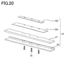
- Fig. 20 shows a disassembled perspective view of the oil retaining member 35.
- the oil retaining member 35 is provided with an oil sucking-in element 37, such as sponge, to suck in oil and a casing 36 covering the lower side of the oil sucking element 37.
- the sucking-in element 37 is placed to come into contact with the end and side damping members 5 and 24.
- the sucking-in element 37 is arranged to come into contact with the raceway rail 1 as well to prevent the oil from leaking out.
- oil sucking-in element isolating plates 38a and 38b are arranged on the upper surface of the oil sucking-in element 37. This arrangement is done in light of the fact that some shapes of the moving block 2 may cause a gap between the oil sucking-in element 37 and the moving block 2. If there is a gap, arranging the oil sucking-in element 37 results in failure in retaining the oil, with the oil leaked out.
- the oil sucking-in element isolating plates 38a and 38b are disposed to fill in such a gap.
- the assembled oil retaining member 35 is secured to the moving block 2 by means of setscrews or other securing members.
- Fig. 21 shows a table apparatus adopted by another embodiment according to the present invention.
- This table apparatus is configured by attaching a table 31 to the moving member 2 of the motion guide device according to the foregoing embodiment.
- a moving member is mounted on an upper surface of the table 31, while the raceway rail 1 is secured to a frame or others of a machine and the moving member 2 moving linearly is assembled with the raceway rail 1.
- the two moving members 2 are assembled with the one raceway rail 1.
- This motion guide device is similar in structure to that adopted by the foregoing embodiment, the identical reference numerals are given for the sake of omitting their explanations.
- the table 31 has a lower surface on which the damping member 32 is secured.
- the damping member 32 is secured to surround the raceway rail 1 and moves along the raceway rail 1.
- the damping member 32 is almost the same in structure as the foregoing end damping member 5.
- the damping member 32 has an opening of which contour is identical with the outer shape of the raceway rail 1 and moves with a slight gap from the raceway rail 1, without contacting the raceway rail 1.
- the gap between the damping member 32 and the raceway rail 1 is filled with a layer of oil.
- the viscosity resistance of the oil is able to generate a braking force in proportion to a movement speed of the table 31, so that the vibration of the table 31 can be damped.
- the present invention can be modified within a range with no change given to the present invention.
- the damping structure according to the present invention can be applied to motion guide devices such as ball splines and ball screws, not limited to the linear guide.
- the raceway rail may extend straightly or bent in a curve. When the raceway rail is bent in a curve, the moving block makes a curved movement relatively to along the raceway rail.
- the surface of the damping member that comes in contact with the oil may not be concavo-convex, but may be planar.
- the end damping member is constructed by laminating the thin plates on one another, but may by constructed by employing a solid member with a plurality of grooves formed thereon.
- Fig. 22 shows a model of parameters employed by this calculation formula.
- the speed V is the faster the movement speed of the moving member 2, the larger the viscosity resistance F.
- the height h is the height of a layer of oil, that is, the width of the gap 16 between each end damping member 5 and the raceway rail 1. The narrower the gap 16, the larger the viscosity resistance F.
- the larger the contact area A the larger the viscosity resistance F.
Landscapes
- Engineering & Computer Science (AREA)
- General Engineering & Computer Science (AREA)
- Mechanical Engineering (AREA)
- Bearings For Parts Moving Linearly (AREA)
- Auxiliary Devices For Machine Tools (AREA)
Applications Claiming Priority (3)
| Application Number | Priority Date | Filing Date | Title |
|---|---|---|---|
| JP2004331221 | 2004-11-15 | ||
| JP2005315299 | 2005-10-28 | ||
| PCT/JP2005/019981 WO2006051707A1 (ja) | 2004-11-15 | 2005-10-31 | 運動案内装置、テーブル装置及び運動案内装置の減衰方法 |
Publications (3)
| Publication Number | Publication Date |
|---|---|
| EP1820983A1 true EP1820983A1 (de) | 2007-08-22 |
| EP1820983A4 EP1820983A4 (de) | 2012-08-15 |
| EP1820983B1 EP1820983B1 (de) | 2016-09-14 |
Family
ID=36336389
Family Applications (1)
| Application Number | Title | Priority Date | Filing Date |
|---|---|---|---|
| EP05800466.4A Ceased EP1820983B1 (de) | 2004-11-15 | 2005-10-31 | Bewegungsführungsvorrichtung, tischvorrichtung und dämpfungsvorrichtung für bewegungsführungsvorrichtung |
Country Status (6)
| Country | Link |
|---|---|
| US (1) | US8231274B2 (de) |
| EP (1) | EP1820983B1 (de) |
| JP (1) | JP4864722B2 (de) |
| KR (1) | KR101202047B1 (de) |
| TW (1) | TWI378189B (de) |
| WO (1) | WO2006051707A1 (de) |
Families Citing this family (3)
| Publication number | Priority date | Publication date | Assignee | Title |
|---|---|---|---|---|
| DE102007006248A1 (de) * | 2007-02-08 | 2008-08-14 | Robert Bosch Gmbh | Linearmodul |
| CN101963216B (zh) * | 2010-08-06 | 2012-10-31 | 济南德佳机器控股有限公司 | 导轨传动机构 |
| USD875150S1 (en) * | 2017-05-31 | 2020-02-11 | Thk Co., Ltd. | End plate for motion guide device |
Family Cites Families (19)
| Publication number | Priority date | Publication date | Assignee | Title |
|---|---|---|---|---|
| JP2633610B2 (ja) * | 1988-03-16 | 1997-07-23 | 日立精工株式会社 | 直線ころがり案内装置 |
| DE8903980U1 (de) | 1989-04-01 | 1989-05-18 | Ina Waelzlager Schaeffler Kg, 8522 Herzogenaurach | Wälzgelagerte Linearführungseinheit |
| US5102235A (en) * | 1991-01-10 | 1992-04-07 | Thomson Industries, Inc. | Linear motion bearing |
| JPH0544726A (ja) | 1991-08-13 | 1993-02-23 | Nippon Thompson Co Ltd | 防振性を有する直動案内摺動ユニツト |
| JPH05133416A (ja) * | 1991-11-07 | 1993-05-28 | Nippon Thompson Co Ltd | 防振性を有する直動案内ユニツト及びその製造方法 |
| JP3636481B2 (ja) * | 1993-07-22 | 2005-04-06 | 日本精工株式会社 | リニアガイドのシール装置 |
| EP0769627B1 (de) * | 1995-10-17 | 2000-08-02 | Deutsche Star GmbH | Linearführungseinrichtung |
| KR100349054B1 (ko) * | 1996-11-11 | 2002-10-19 | 티에치케이 가부시끼가이샤 | 직선운동장치및이에사용되는윤활유공급장치 |
| JP4112076B2 (ja) * | 1998-06-05 | 2008-07-02 | 日本トムソン株式会社 | 潤滑プレートを備えた直動案内ユニット |
| DE59910887D1 (de) * | 1998-08-27 | 2004-11-25 | Schneeberger Holding Ag Roggwi | Linearbewegungsführung |
| JP3308944B2 (ja) * | 1998-12-04 | 2002-07-29 | テイエチケー株式会社 | 案内装置の防塵構造 |
| TW429290B (en) * | 2000-05-24 | 2001-04-11 | Hiwin Tech Corp | A linear guide way |
| JP2002242930A (ja) * | 2001-02-16 | 2002-08-28 | Okuma Corp | 案内装置 |
| JP4004873B2 (ja) * | 2001-09-21 | 2007-11-07 | Thk株式会社 | 案内装置のシール装置及び案内装置 |
| JP2004176825A (ja) | 2002-11-27 | 2004-06-24 | Thk Co Ltd | ダイナミックダンパ付運動案内装置及びテーブル装置 |
| JP2005083500A (ja) * | 2003-09-09 | 2005-03-31 | Nsk Ltd | 直動案内装置 |
| JP4335697B2 (ja) * | 2004-01-06 | 2009-09-30 | 株式会社岡本工作機械製作所 | 油静圧直動案内装置 |
| JP4615466B2 (ja) * | 2006-03-22 | 2011-01-19 | 日本トムソン株式会社 | 高密封シール装置を備えた直動案内ユニット |
| DE102006015478B4 (de) * | 2006-04-03 | 2014-10-02 | Franke & Heydrich Kg | Wälzlager in Form einer Dreh- oder Linearführung |
-
2005
- 2005-10-31 US US11/719,352 patent/US8231274B2/en not_active Expired - Fee Related
- 2005-10-31 KR KR1020077013334A patent/KR101202047B1/ko not_active Expired - Fee Related
- 2005-10-31 EP EP05800466.4A patent/EP1820983B1/de not_active Ceased
- 2005-10-31 WO PCT/JP2005/019981 patent/WO2006051707A1/ja not_active Ceased
- 2005-10-31 JP JP2006544840A patent/JP4864722B2/ja not_active Expired - Fee Related
- 2005-11-14 TW TW094139866A patent/TWI378189B/zh not_active IP Right Cessation
Also Published As
| Publication number | Publication date |
|---|---|
| US8231274B2 (en) | 2012-07-31 |
| WO2006051707A1 (ja) | 2006-05-18 |
| US20090161996A1 (en) | 2009-06-25 |
| KR20070086136A (ko) | 2007-08-27 |
| TW200628707A (en) | 2006-08-16 |
| KR101202047B1 (ko) | 2012-11-15 |
| JP4864722B2 (ja) | 2012-02-01 |
| EP1820983A4 (de) | 2012-08-15 |
| JPWO2006051707A1 (ja) | 2008-08-07 |
| TWI378189B (en) | 2012-12-01 |
| EP1820983B1 (de) | 2016-09-14 |
Similar Documents
| Publication | Publication Date | Title |
|---|---|---|
| US5927858A (en) | Linear motion rolling guide unit | |
| JP6669275B2 (ja) | ボールねじ装置 | |
| CN101080580B (zh) | 运动引导装置以及运动引导装置的润滑方法 | |
| JPH05133416A (ja) | 防振性を有する直動案内ユニツト及びその製造方法 | |
| JP7499839B2 (ja) | 運動案内装置および該運動案内装置において使用される潤滑経路部品 | |
| JP5103057B2 (ja) | ローラ形式の直動案内ユニット | |
| EP1820983B1 (de) | Bewegungsführungsvorrichtung, tischvorrichtung und dämpfungsvorrichtung für bewegungsführungsvorrichtung | |
| US11771217B2 (en) | Sliding table | |
| US7401978B2 (en) | Linear motion guiding apparatus | |
| JP3516209B2 (ja) | 直動転がり案内ユニット | |
| JPH08114222A (ja) | ローラー型直綿案内装置 | |
| JP4660601B2 (ja) | 軌道部材およびこの軌道部材を用いた運動案内装置 | |
| CN100545472C (zh) | 运动导向装置、工作台装置以及运动导向装置的减震方法 | |
| CN115306824B (zh) | 线性引导件 | |
| CN119308939B (zh) | 一种基于柔性弹性元件的液体静压导轨 | |
| JP5377847B2 (ja) | 運動装置 | |
| EP1677016B1 (de) | Lineare führungsvorrichtung | |
| US7578620B2 (en) | Linear guide device | |
| CN213176476U (zh) | 一种用于自动化设备的导轨 | |
| JP3591912B2 (ja) | リニアガイド装置の案内レール | |
| WO2025173438A1 (ja) | 転がり案内装置 | |
| JP2026019430A (ja) | シール部材 | |
| JP6186264B2 (ja) | 潤滑構造を備えるリニアガイド | |
| JP2025150722A (ja) | 転がり案内装置 | |
| JPH0742734A (ja) | ボール・ころ併用リニアガイド装置 |
Legal Events
| Date | Code | Title | Description |
|---|---|---|---|
| PUAI | Public reference made under article 153(3) epc to a published international application that has entered the european phase |
Free format text: ORIGINAL CODE: 0009012 |
|
| 17P | Request for examination filed |
Effective date: 20070530 |
|
| AK | Designated contracting states |
Kind code of ref document: A1 Designated state(s): DE FR |
|
| DAX | Request for extension of the european patent (deleted) | ||
| RBV | Designated contracting states (corrected) |
Designated state(s): DE FR |
|
| A4 | Supplementary search report drawn up and despatched |
Effective date: 20120718 |
|
| RIC1 | Information provided on ipc code assigned before grant |
Ipc: F16C 29/08 20060101ALI20120712BHEP Ipc: F16C 29/06 20060101AFI20120712BHEP Ipc: B23Q 11/00 20060101ALI20120712BHEP Ipc: F16C 29/00 20060101ALI20120712BHEP |
|
| RIC1 | Information provided on ipc code assigned before grant |
Ipc: F16C 29/08 20060101ALI20120719BHEP Ipc: B23Q 11/00 20060101ALI20120719BHEP Ipc: F16C 29/06 20060101AFI20120719BHEP Ipc: F16C 29/00 20060101ALI20120719BHEP |
|
| 17Q | First examination report despatched |
Effective date: 20130204 |
|
| R17C | First examination report despatched (corrected) |
Effective date: 20130204 |
|
| GRAP | Despatch of communication of intention to grant a patent |
Free format text: ORIGINAL CODE: EPIDOSNIGR1 |
|
| INTG | Intention to grant announced |
Effective date: 20160531 |
|
| GRAS | Grant fee paid |
Free format text: ORIGINAL CODE: EPIDOSNIGR3 |
|
| GRAA | (expected) grant |
Free format text: ORIGINAL CODE: 0009210 |
|
| AK | Designated contracting states |
Kind code of ref document: B1 Designated state(s): DE FR |
|
| REG | Reference to a national code |
Ref country code: FR Ref legal event code: PLFP Year of fee payment: 12 |
|
| REG | Reference to a national code |
Ref country code: DE Ref legal event code: R096 Ref document number: 602005050250 Country of ref document: DE |
|
| REG | Reference to a national code |
Ref country code: DE Ref legal event code: R097 Ref document number: 602005050250 Country of ref document: DE |
|
| PLBE | No opposition filed within time limit |
Free format text: ORIGINAL CODE: 0009261 |
|
| STAA | Information on the status of an ep patent application or granted ep patent |
Free format text: STATUS: NO OPPOSITION FILED WITHIN TIME LIMIT |
|
| 26N | No opposition filed |
Effective date: 20170615 |
|
| REG | Reference to a national code |
Ref country code: FR Ref legal event code: PLFP Year of fee payment: 13 |
|
| PGFP | Annual fee paid to national office [announced via postgrant information from national office to epo] |
Ref country code: FR Payment date: 20170918 Year of fee payment: 13 |
|
| PGFP | Annual fee paid to national office [announced via postgrant information from national office to epo] |
Ref country code: DE Payment date: 20171025 Year of fee payment: 13 |
|
| REG | Reference to a national code |
Ref country code: DE Ref legal event code: R119 Ref document number: 602005050250 Country of ref document: DE |
|
| PG25 | Lapsed in a contracting state [announced via postgrant information from national office to epo] |
Ref country code: DE Free format text: LAPSE BECAUSE OF NON-PAYMENT OF DUE FEES Effective date: 20190501 |
|
| PG25 | Lapsed in a contracting state [announced via postgrant information from national office to epo] |
Ref country code: FR Free format text: LAPSE BECAUSE OF NON-PAYMENT OF DUE FEES Effective date: 20181031 |