EP1821013A2 - Soupape à plusieurs voies - Google Patents
Soupape à plusieurs voies Download PDFInfo
- Publication number
- EP1821013A2 EP1821013A2 EP07003111A EP07003111A EP1821013A2 EP 1821013 A2 EP1821013 A2 EP 1821013A2 EP 07003111 A EP07003111 A EP 07003111A EP 07003111 A EP07003111 A EP 07003111A EP 1821013 A2 EP1821013 A2 EP 1821013A2
- Authority
- EP
- European Patent Office
- Prior art keywords
- valve
- way valve
- valve according
- housing
- actuating
- Prior art date
- Legal status (The legal status is an assumption and is not a legal conclusion. Google has not performed a legal analysis and makes no representation as to the accuracy of the status listed.)
- Withdrawn
Links
Images


Classifications
-
- F—MECHANICAL ENGINEERING; LIGHTING; HEATING; WEAPONS; BLASTING
- F16—ENGINEERING ELEMENTS AND UNITS; GENERAL MEASURES FOR PRODUCING AND MAINTAINING EFFECTIVE FUNCTIONING OF MACHINES OR INSTALLATIONS; THERMAL INSULATION IN GENERAL
- F16K—VALVES; TAPS; COCKS; ACTUATING-FLOATS; DEVICES FOR VENTING OR AERATING
- F16K31/00—Actuating devices; Operating means; Releasing devices
- F16K31/44—Mechanical actuating means
- F16K31/52—Mechanical actuating means with crank, eccentric, or cam
- F16K31/524—Mechanical actuating means with crank, eccentric, or cam with a cam
- F16K31/52408—Mechanical actuating means with crank, eccentric, or cam with a cam comprising a lift valve
- F16K31/52416—Mechanical actuating means with crank, eccentric, or cam with a cam comprising a lift valve comprising a multiple-way lift valve
-
- F—MECHANICAL ENGINEERING; LIGHTING; HEATING; WEAPONS; BLASTING
- F16—ENGINEERING ELEMENTS AND UNITS; GENERAL MEASURES FOR PRODUCING AND MAINTAINING EFFECTIVE FUNCTIONING OF MACHINES OR INSTALLATIONS; THERMAL INSULATION IN GENERAL
- F16K—VALVES; TAPS; COCKS; ACTUATING-FLOATS; DEVICES FOR VENTING OR AERATING
- F16K11/00—Multiple-way valves, e.g. mixing valves; Pipe fittings incorporating such valves
- F16K11/02—Multiple-way valves, e.g. mixing valves; Pipe fittings incorporating such valves with all movable sealing faces moving as one unit
- F16K11/08—Multiple-way valves, e.g. mixing valves; Pipe fittings incorporating such valves with all movable sealing faces moving as one unit comprising only taps or cocks
- F16K11/085—Multiple-way valves, e.g. mixing valves; Pipe fittings incorporating such valves with all movable sealing faces moving as one unit comprising only taps or cocks with cylindrical plug
- F16K11/0853—Multiple-way valves, e.g. mixing valves; Pipe fittings incorporating such valves with all movable sealing faces moving as one unit comprising only taps or cocks with cylindrical plug having all the connecting conduits situated in a single plane perpendicular to the axis of the plug
-
- F—MECHANICAL ENGINEERING; LIGHTING; HEATING; WEAPONS; BLASTING
- F16—ENGINEERING ELEMENTS AND UNITS; GENERAL MEASURES FOR PRODUCING AND MAINTAINING EFFECTIVE FUNCTIONING OF MACHINES OR INSTALLATIONS; THERMAL INSULATION IN GENERAL
- F16K—VALVES; TAPS; COCKS; ACTUATING-FLOATS; DEVICES FOR VENTING OR AERATING
- F16K27/00—Construction of housing; Use of materials therefor
- F16K27/02—Construction of housing; Use of materials therefor of lift valves
- F16K27/0263—Construction of housing; Use of materials therefor of lift valves multiple way valves
Definitions
- the invention relates to a multi-way valve according to the preamble of claim 1.
- Such a multi-way valve is for example in the EP 13 08 658 A2 described.
- the invention has for its object to provide a simply constructed and compact multi-way valve with easy operation and safe sealing valve bodies.
- valve bodies associated with the connecting lines are arranged on the side facing away from the interior of the multi-way valve side of the junctions. As a result, the valve bodies associated with the connecting lines are arranged such that they are acted upon during operation with negative pressure and are thus sucked against the valve seat. As a result, a secure sealing of the connecting lines during operation of the field sprayer, when the interior of the multi-way valve is acted upon by negative pressure through the suction line, ensured by the valve body.
- the openings of the connecting lines on their side facing away from the interior of the multi-way valve side of the housing is arranged a cooperating with the respective valve body valve seat.
- an opening which can be used as a discharge line is arranged in the multiway valve, that this drainage line is likewise arranged a valve body corresponding to the connecting lines.
- An advantageous embodiment of a multi-way valve in particular when used in an agricultural field sprayer, can be achieved in that at least one connecting line as a discharge line and the other connecting lines designed as supply lines and / or serves.
- connection lines are arranged at least approximately star-shaped opening into the housing. This ensures that the connection lines open optimally in the housing, all leads are arranged in an optimal manner to the central actuator.
- the connection lines can thus be uniformly distributed around the actuating element einmündend.
- the valve bodies associated with the junctions of the connecting lines are likewise arranged in an optimum and uniformly distributed manner with respect to the actuating element.
- the connection lines are arranged at least approximately in one direction into the housing on a plane.
- a particularly compact design of the Multi-way valve is achieved in that the suction line is arranged to open at an angle to the plane of the connecting lines in the plane lying in the housing. The fact that the suction line is arranged in a different plane than the connecting lines, results in a multi-way valve with an extremely compact size.
- Simple actuation of the individual valve bodies can be achieved in that central actuating element has at least one actuating cam arranged eccentrically to the axis of rotation of the actuating element.
- the actuating element has at least two actuation cams arranged one behind the other and offset from one another.
- the valve body on the one hand with a small force in the open position even if a negative pressure acts on the valve body during operation, so to open with a small force and on the other hand, a small adjustment the valve body in its largest Opening position can be brought by means of the actuating cam of the central actuator, it is provided that the actuating cam in its switching range for actuating the respective valve body has at least two different pitch ranges, first to open the access line a relatively small pitch and in its subsequent area a much larger pitch.
- valve bodies each associated with a spring such that the spring, the valve body relative to the opening of the access line in his Closed position presses.
- the valve body has a valve disk that is arranged on both sides of the valve disk and perpendicular to this guide pins, which are slidably mounted in guides of the housing.
- the actuating element facing the guide pin is arranged eccentrically of the valve disc.
- the plain bearings for receiving the guide pins of the valve disc are arranged eccentrically to the inlet opening of the supply line.
- At least one of the guide pins and the associated plain bearings are non-circular, preferably rectangular or square.
- valve disc with slotted guide pin on the actuating cam side facing and valve disc with a guide pin with a constant end piece on the actuating cam side facing are present, that a middle cam and two arranged on the side of the central cam are present, that the middle and the side cams are arranged offset to one another.
- Such a multi-way valve is used advantageously in an agricultural field sprayer.
- the setting of the field sprayer for the respective operating mode is considerably simplified because a plurality of valves of conventional design are combined in the multi-way valve according to the invention, thus erroneous adjustments due to the inventive design of the valve are excluded.
- the agricultural field sprayer has a liquid tank 1, a pump 2, a pressure control valve 3, a metering valve 4, the return lines 5, the stirring line 6, and the spray lines 7.
- the connecting line 8 is connected.
- This connecting line 8 opens into the multi-way valve 9 a.
- the suction line 10 of the pump 2 connected to the rear of the housing 11 of the multi-way valve 9 opening.
- the filter 12 is arranged.
- the pressure line 13 leads to the pressure control valve 3 and the metering 4.
- the pump 2 is driven in a known and therefore not shown manner by a power source, such as a PTO of a tractor or a hydraulic pump.
- connection lead coming from the fresh water tank 14 and designed as a connection line supply line 15 connection lead coming from the fresh water tank 14 and designed as a connection line supply line 15
- another line of the field spray system which is designed as a supply line, can be connected or connected to the connection of the discharge line 17.
- the multi-way valve 9 has a central actuating element 19 to be actuated by a hand lever 18, by means of which the valve body 20 assigned to the connecting lines 8, 13, 15, 17 and to be described in more detail below are to be actuated.
- the respective connecting lines 8,13,15,17 associated valve body 20 can be actuated to 9 via the interior 21 of the housing 11 of the multi-way valve individual connecting lines 8,13,15,17 with the suction line 10 or individual connection lines. 8 , 13,15,17 to each other to connect with each other, so that liquid from each of the released from the valve body 20 connecting line 8,13,15 of the suction line 10 or the discharge line 17 can flow.
- the pump sucks 2 via the suction line 10 and the filter 12 either the spray liquid from the reservoir 1 via the line 8 or for filling the liquid tank 1 water over the supply line designed as a suction hose 16 or to the tank 1 and the lines 7, via the line 15 water from the fresh water tank 14 at.
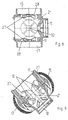
- the multi-way valve according to FIGS. 2 to 17 has the housing 11.
- the switching shaft 22 of the central actuating element 19 is rotatably supported by a two-sided bearing 23.
- the switching shaft 22 is led out of the housing 11.
- At the lead-out end 24 of the hand lever 18 is arranged rotationally fixed.
- two actuation cams 25, 26 arranged offset to one another on the switching shaft 22 of the central actuating element 19 are used for actuating the valve bodies 20 inserted into the housing 11 and the connection lines 8, 13, 15, 17.
- connection lines 8,13,15,17 open are arranged on the interior 21 of the multi-way valve 9 side facing away from the housing 11 each with the respective valve body 20 cooperating valve seats 28.
- the connecting elements 8,13,15,17 associated valve body 20 are arranged on the interior 21 of the multi-way valve 9 side facing away from the junctions 27, such as Fig. 4 and 5 show.
- the valve body 20 have a valve plate 29. Furthermore, on both sides of the valve disk 29 and perpendicular to this guide pins 30,31 are arranged. These guide pins 30,31 are slidably mounted in guides 32,33 of the housing 9, which are arranged in the region of the junctions 27 of the connecting lines 8,13,15,17.
- the actuating pin 25, 26 of the actuating element 19 facing guide pin 30 is arranged eccentrically of the valve disk 29, as Figs. 15 and 16 show. Also, the plain bearings 32 for receiving the guide pins 30 of the valve plate 29 on the interior 21 of the housing 11 of the Multi-way valve 9 and the actuating cam 25,26 assigned to the central actuating element 19, off-center of the junctions 27 of the supply line or the connecting line 8,13,15,17 arranged.
- the valve plate 29 with its guide pins 30,31 can not rotate, the actuating cam 25,26 facing guide pin 30 and the associated sliding bearing 32 is rectangular.
- the guide pins 30 are each associated with an actuating cam 25,26 so as to be able to realize corresponding combination options for the common and separate actuation of the individual lines 8,13,15,17 associated valve body 20.
- the supply lines 8, 13, 15 and the discharge lines 17 are, as shown in FIGS. 3 and 5, arranged in a star shape opening into the housing 9.
- the connecting lines designed as feed lines 8, 13, 15 and discharge line 17 are arranged on one level into the housing 11, while the suction line 10 lies on a plane lying at the level of the connecting line 8, 13, 15, 17 at an angle in the housing 11 is arranged einmündend, as shown in FIGS. 2 and 4 show.
- the suction line 10 opens out of the plane on which the connecting lines 8,13,15,17 in the housing 11 in the housing.
- the actuating cams 25,26 can be arranged in different positions on the shift shaft to each other.
- the respective actuating cam 25,26 has two different pitch regions 34,35 in its switching area for actuating the respective valve body 20.
- the actuating cam 25,26 for opening the access lines 8,13,15,17 for actuating the valve body 20 in slope region 34 has a relatively small pitch and in its subsequent region 35 a much larger Climb up.
- the slope of the actuating cam in its switching region 34 with a larger way.
- the valve bodies 20 is on its the inner region 21 of the multi-way valve 9 side facing away from a spring 36 assigned such that the spring 36 presses the valve body 20 relative to the junctions 29 of the connecting lines 8,13,15,17 in its closed position, so that the valve disc 29 with its associated sealing ring 37, which is not shown in FIGS. 16 and 17, is pressed against its valve seat 28.
- the valve disk 36 is designed in such a way that at least the opposing force can be applied to any water column in the fluid system which may possibly be present on the connection lines 8, 13, 15.
- the valve plates 29 of the valve body 20 are pulled against the valve seat 28 by the suction line 10 which is present on the suction connection 10.
- the switching cams 25, 26 have a notch 37 on their highest elevation.
- this notch 37 summarizes the guide pin 30 of the valve body 20 in its largest open position. This will ensure a secure positioning the PrimabetHence,s institutea 19 achieved with the actuating cam 25,26.
- valve disc 29 or two valve disc 29 can be lifted from the valve seat 28.
- two connecting pipes 8, 13, 15, 17 can be connected to one another.
- the lines leading to the tank 1 8 can be connected to the drain port 17, so that liquids can be discharged from the tank 1.
- the lines 8 and 15 can be connected to each other, for example.
- Figs. 18 to 20 show a differently configured actuating cam 38,39, which are arranged on a switching shaft of a multi-way valve, as described above, and guide pins 40,41,42 of the valve body 43,44.
- the one valve body 43 has a valve disk 45 with a slotted guide pin 41 on the actuating cam 38,39 side facing, while the other valve body 44 a valve actuator 45 an unslotted guide pin with a constant thickness.
- the middle cam 39 can move through the slotted portion 46 of the guide pin 41 without contacting the guide pin 41 and lifting the valve plate 45 of the valve body 43.
- the actuation of the valve disk 45 with the slotted guide pin 41 is effected exclusively by the two actuating cams 38 arranged laterally of the middle actuating cam.
- the unslotted guide pin 42 can be actuated by both actuating cams 38, 39 in each case.
Landscapes
- Engineering & Computer Science (AREA)
- General Engineering & Computer Science (AREA)
- Mechanical Engineering (AREA)
- Mechanically-Actuated Valves (AREA)
- Multiple-Way Valves (AREA)
Applications Claiming Priority (1)
| Application Number | Priority Date | Filing Date | Title |
|---|---|---|---|
| DE102006006986 | 2006-02-15 |
Publications (2)
| Publication Number | Publication Date |
|---|---|
| EP1821013A2 true EP1821013A2 (fr) | 2007-08-22 |
| EP1821013A3 EP1821013A3 (fr) | 2014-12-03 |
Family
ID=38055217
Family Applications (2)
| Application Number | Title | Priority Date | Filing Date |
|---|---|---|---|
| EP07002783A Withdrawn EP1821012A3 (fr) | 2006-02-15 | 2007-02-09 | Soupape à plusieurs voies |
| EP07003111.7A Withdrawn EP1821013A3 (fr) | 2006-02-15 | 2007-02-14 | Soupape à plusieurs voies |
Family Applications Before (1)
| Application Number | Title | Priority Date | Filing Date |
|---|---|---|---|
| EP07002783A Withdrawn EP1821012A3 (fr) | 2006-02-15 | 2007-02-09 | Soupape à plusieurs voies |
Country Status (1)
| Country | Link |
|---|---|
| EP (2) | EP1821012A3 (fr) |
Families Citing this family (2)
| Publication number | Priority date | Publication date | Assignee | Title |
|---|---|---|---|---|
| GB201321491D0 (en) * | 2013-12-05 | 2014-01-22 | Agco Netherlands Bv | Agricultural sprayer pump system |
| DE102020117751A1 (de) | 2020-07-06 | 2022-01-13 | Horsch Leeb Application Systems Gmbh | Feldspritzensystem mit Flüssigkeitsleitungsknoten |
Citations (1)
| Publication number | Priority date | Publication date | Assignee | Title |
|---|---|---|---|---|
| EP1308658A2 (fr) | 2001-11-06 | 2003-05-07 | Amazonen-Werke H. Dreyer GmbH & Co. KG | Robinet à voies multiples |
Family Cites Families (4)
| Publication number | Priority date | Publication date | Assignee | Title |
|---|---|---|---|---|
| FR1201127A (fr) * | 1958-08-05 | 1959-12-28 | Majeste La Reine De Droit Du C | Dispositif de soupapes pour sorties sélectives de réservoirs inclinables et retournables d'aéronefs |
| FR1408753A (fr) * | 1964-06-22 | 1965-08-20 | Robinet mélangeur mitigeur à grande plage de réglage | |
| GB1445085A (en) * | 1972-11-02 | 1976-08-04 | Gessey Son Ltd | Mixing valves |
| US7533697B2 (en) * | 2003-10-22 | 2009-05-19 | Parker-Hannifin Corporation | Fuel valve assembly |
-
2007
- 2007-02-09 EP EP07002783A patent/EP1821012A3/fr not_active Withdrawn
- 2007-02-14 EP EP07003111.7A patent/EP1821013A3/fr not_active Withdrawn
Patent Citations (1)
| Publication number | Priority date | Publication date | Assignee | Title |
|---|---|---|---|---|
| EP1308658A2 (fr) | 2001-11-06 | 2003-05-07 | Amazonen-Werke H. Dreyer GmbH & Co. KG | Robinet à voies multiples |
Also Published As
| Publication number | Publication date |
|---|---|
| EP1821012A2 (fr) | 2007-08-22 |
| EP1821013A3 (fr) | 2014-12-03 |
| EP1821012A3 (fr) | 2010-04-21 |
Similar Documents
| Publication | Publication Date | Title |
|---|---|---|
| EP2593235B1 (fr) | Tête de buse multiple avec vanne multivoies | |
| DE2335214C3 (de) | Selbstreinigender Flüssigkeitsfilter | |
| EP2283262B1 (fr) | Vanne à plusieurs voies d'un système d'alimentation en combustible d'une turbine à gaz | |
| DE102018131802B4 (de) | Vorgesteuertes Ventil zur Verteilung eines flüssigen Mediums | |
| WO2018077348A1 (fr) | Dispositif de répartition d'eau de lave-vitre à soupapes multiples | |
| EP0483700A1 (fr) | Appareil pour préparer des boissons chaudes | |
| DE3324308A1 (de) | Verteilerhahn | |
| WO2002025147A1 (fr) | Cartouche pour robinetterie sanitaire | |
| EP1821017A2 (fr) | Soupape à plusieurs voies | |
| EP1821013A2 (fr) | Soupape à plusieurs voies | |
| DE102007007870A1 (de) | Mehrwegeventil | |
| EP0791772A2 (fr) | Soupape à trois voies pour jonction hydraulique | |
| DE3509720C2 (fr) | ||
| DE102008006450B4 (de) | Mehrwegeventil für einen Flüssigkeitskreislauf | |
| EP3026307B1 (fr) | Unite de soupape | |
| DE102007007869A1 (de) | Mehrwegeventil | |
| DE2329528A1 (de) | Steuerventil, bzw. ventilschieber mit einer vielzahl von auslaessen | |
| DE3925270C2 (fr) | ||
| DE10154451A1 (de) | Mehrwegehahn | |
| DE29920941U1 (de) | Molchbares Dreiwegeventil | |
| DE102006023055A1 (de) | Mehrwegeventil | |
| DE102020101617A1 (de) | Mehrwegventil für Fluid für eine Gerätezubereitungsvorrichtung, Mehrfluid-Mehrwegventil für eine Gerätezubereitungsvorrichtung und Gerätezubereitungsvorrichtung, insbesondere Kaffeemaschine | |
| DE4323893C1 (de) | Filterkopf | |
| DE2134272A1 (de) | Dreiwege-ventil mit druckentlasteten ventiltellern | |
| DE19737005A1 (de) | Vorrichtung zur Steuerung eines doppelt wirkenden Lenkzylinders |
Legal Events
| Date | Code | Title | Description |
|---|---|---|---|
| PUAI | Public reference made under article 153(3) epc to a published international application that has entered the european phase |
Free format text: ORIGINAL CODE: 0009012 |
|
| AK | Designated contracting states |
Kind code of ref document: A2 Designated state(s): AT BE BG CH CY CZ DE DK EE ES FI FR GB GR HU IE IS IT LI LT LU LV MC NL PL PT RO SE SI SK TR |
|
| AX | Request for extension of the european patent |
Extension state: AL BA HR MK YU |
|
| PUAL | Search report despatched |
Free format text: ORIGINAL CODE: 0009013 |
|
| AK | Designated contracting states |
Kind code of ref document: A3 Designated state(s): AT BE BG CH CY CZ DE DK EE ES FI FR GB GR HU IE IS IT LI LT LU LV MC NL PL PT RO SE SI SK TR |
|
| AX | Request for extension of the european patent |
Extension state: AL BA HR MK RS |
|
| RIC1 | Information provided on ipc code assigned before grant |
Ipc: F16K 11/085 20060101ALI20141024BHEP Ipc: F16K 11/00 20060101AFI20141024BHEP Ipc: F16K 31/524 20060101ALI20141024BHEP Ipc: F16K 27/02 20060101ALI20141024BHEP |
|
| AKY | No designation fees paid | ||
| AXX | Extension fees paid |
Extension state: BA Extension state: MK Extension state: AL Extension state: HR Extension state: RS |
|
| REG | Reference to a national code |
Ref country code: DE Ref legal event code: R108 |
|
| STAA | Information on the status of an ep patent application or granted ep patent |
Free format text: STATUS: THE APPLICATION IS DEEMED TO BE WITHDRAWN |
|
| 18D | Application deemed to be withdrawn |
Effective date: 20150604 |