EP1821018B1 - Thermostatvorrichtung - Google Patents
Thermostatvorrichtung Download PDFInfo
- Publication number
- EP1821018B1 EP1821018B1 EP04822612.0A EP04822612A EP1821018B1 EP 1821018 B1 EP1821018 B1 EP 1821018B1 EP 04822612 A EP04822612 A EP 04822612A EP 1821018 B1 EP1821018 B1 EP 1821018B1
- Authority
- EP
- European Patent Office
- Prior art keywords
- spring
- latch
- valve
- lower frame
- thermostat
- Prior art date
- Legal status (The legal status is an assumption and is not a legal conclusion. Google has not performed a legal analysis and makes no representation as to the accuracy of the status listed.)
- Expired - Lifetime
Links
Images



Classifications
-
- F—MECHANICAL ENGINEERING; LIGHTING; HEATING; WEAPONS; BLASTING
- F16—ENGINEERING ELEMENTS AND UNITS; GENERAL MEASURES FOR PRODUCING AND MAINTAINING EFFECTIVE FUNCTIONING OF MACHINES OR INSTALLATIONS; THERMAL INSULATION IN GENERAL
- F16K—VALVES; TAPS; COCKS; ACTUATING-FLOATS; DEVICES FOR VENTING OR AERATING
- F16K31/00—Actuating devices; Operating means; Releasing devices
- F16K31/002—Actuating devices; Operating means; Releasing devices actuated by temperature variation
-
- G—PHYSICS
- G05—CONTROLLING; REGULATING
- G05D—SYSTEMS FOR CONTROLLING OR REGULATING NON-ELECTRIC VARIABLES
- G05D23/00—Control of temperature
- G05D23/01—Control of temperature without auxiliary power
- G05D23/02—Control of temperature without auxiliary power with sensing element expanding and contracting in response to changes of temperature
- G05D23/021—Control of temperature without auxiliary power with sensing element expanding and contracting in response to changes of temperature the sensing element being a non-metallic solid, e.g. elastomer, paste
- G05D23/022—Control of temperature without auxiliary power with sensing element expanding and contracting in response to changes of temperature the sensing element being a non-metallic solid, e.g. elastomer, paste the sensing element being placed within a regulating fluid flow
-
- F—MECHANICAL ENGINEERING; LIGHTING; HEATING; WEAPONS; BLASTING
- F16—ENGINEERING ELEMENTS AND UNITS; GENERAL MEASURES FOR PRODUCING AND MAINTAINING EFFECTIVE FUNCTIONING OF MACHINES OR INSTALLATIONS; THERMAL INSULATION IN GENERAL
- F16K—VALVES; TAPS; COCKS; ACTUATING-FLOATS; DEVICES FOR VENTING OR AERATING
- F16K27/00—Construction of housing; Use of materials therefor
- F16K27/02—Construction of housing; Use of materials therefor of lift valves
-
- F—MECHANICAL ENGINEERING; LIGHTING; HEATING; WEAPONS; BLASTING
- F01—MACHINES OR ENGINES IN GENERAL; ENGINE PLANTS IN GENERAL; STEAM ENGINES
- F01P—COOLING OF MACHINES OR ENGINES IN GENERAL; COOLING OF INTERNAL-COMBUSTION ENGINES
- F01P11/00—Component parts, details, or accessories not provided for in, or of interest apart from, groups F01P1/00 - F01P9/00
- F01P11/02—Liquid-coolant filling, overflow, venting, or draining devices
- F01P11/0285—Venting devices
-
- F—MECHANICAL ENGINEERING; LIGHTING; HEATING; WEAPONS; BLASTING
- F01—MACHINES OR ENGINES IN GENERAL; ENGINE PLANTS IN GENERAL; STEAM ENGINES
- F01P—COOLING OF MACHINES OR ENGINES IN GENERAL; COOLING OF INTERNAL-COMBUSTION ENGINES
- F01P7/00—Controlling of coolant flow
- F01P7/14—Controlling of coolant flow the coolant being liquid
- F01P7/16—Controlling of coolant flow the coolant being liquid by thermostatic control
Definitions
- the present invention relates to a thermostat for variably controlling water temperature in, for example, a cooling water temperature control system for variably controlling the cooling water temperature of an internal combustion engine (hereinafter referred to as an engine) used in an automobile or the like.
- a cooling water temperature control system for variably controlling the cooling water temperature of an internal combustion engine (hereinafter referred to as an engine) used in an automobile or the like.
- Thermostats arranged in, for example, the cooling water system of an engine or the like comprise a thermoelement with a built-in thermally-expanding body that expands and contracts in response to detected changes in temperature of the cooling water flowing in a circulatory passage. These thermostats function to maintain the cooling water at a prescribed temperature based on the opening and closing of a valve as a result of volumetric change that accompanies the expansion and contraction of the thermally-expanding body.
- thermoelement In conventional thermostats a frame for covering the thermoelement is formed from metal, the frame being assembled by, for example, the coupling of upper and lower frame members by caulking or welding.
- thermoelement is unsuitable, the frame cannot be easily disassembled and the replacement of the element takes time.
- Cited reference 1 Japanese Laid-Open Utility Model Application No. S52-64243 discloses an example structure of an easily assembled and disassembled thermostat designed with these problems in mind.
- Fig. 6 shows an example configuration of the thermostat of cited reference 1.
- Fig. 6(a) is a front elevational view of the thermostat, and
- Fig. 6(b) is a plan view thereof as seen from below.
- a thermostat 50 comprises a temperature-sensitive thermoelement 54 interposed in an opposing gap 53 between an opposingly provided upper frame 51 and disk-shaped lower frame 52.
- a piston 55 is provided to protrude from the upper end of the thermoelement 54, the piston 55 engaging with an apex part inner-side surface 51a of the upper frame 51.
- a flanged valve 56 is formed on the outer perimeter surface of the thermoelement 54, an outer perimeter bevel-edged surface 56a thereof being elastically pressure-contacted against an inner perimeter surface 51b of the upper frame 51 by a coil spring 57 provided on the inner surface of the lower frame 52.
- latch hooks 51c are formed in the lower end part of the upper frame 51 and, as shown in Fig. 6(b) , latch slits 52a are formed in the lower frame 52.
- These latch slits 52a have an opening that is larger than the latch hooks 51c and, continuously therewith in the circumferential direction, an opening part that is smaller than the latch hooks 51c. Therefore, the upper and lower frames can be easily assembled by an operation in which the coil spring 57 is pressed to introduce the latch hooks 51c into the latch slits 52a and the upper frame 51 or lower frame 52 are slightly turned. Disassembly can be performed similarly easily by an operation in which the upper frame 51 and lower frame 52 are slightly turned.
- the structure is assembled by latching dispensing with the conventionally performed steps of caulking and welding. Accordingly, because the assembly and disassembly thereof can be performed comparatively easily, productivity is improved and, if it is determined through characteristic testing following assembly that the thermoelement is unsuitable, the frame can be easily disassembled in order to replace the element, and a uniformity of product characteristics can be easily achieved.
- Cited reference 1 Japanese Laid-Open Utility Model Application No. S52-64243 (page 4 line 2 to page 5 line 5, and Figs. 2 and 3 )
- the frame for covering the thermoelement formed from metal of conventional thermostats described above is a primary cause of the increased weight and increased cost of the thermostat.
- the thermostat pertaining to the present invention for resolving the problems described above constitutes a thermostat installed in a housing that is connected to a plurality of passages through which a cooling water flows, the passages being linked or blocked by the actuation of a valve in response to temperature changes of the cooling water, characterized in that it comprises: a thermoelement having a piston that slides up and down as a result of the temperature changes and a flanged valve in its perimeter edge, the flanged valve being actuated by the advancing and retreating action of the piston; a spring which is arranged so as to surround the thermoelement and one end of which elastically pressure-contacts the rear side of the flanged valve; an upper frame in which a valve seat that abuts against the upper side of the flanged valve is formed; and a lower frame that is pressure-contacted by the other end of the spring, wherein latch frames are formed in the upper frame and a plurality of latch hooks that latch to the latch frames are formed in the lower frame, the upper frame
- the upper and lower frames are formed from an elastic material (for example, a material formed by the press-molding of a resin or thin metal plate or the like) and are latched and fixed utilizing this elasticity in this way, the thermostat can be easily assembled and disassembled. Productivity is improved as a result and, if it is determined through characteristic testing following assembly that the thermoelement is unsuitable, the frame can be easily disassembled in order to replace the element, and a uniformity of product characteristics can be easily achieved.
- an elastic material for example, a material formed by the press-molding of a resin or thin metal plate or the like
- the forming of the upper and lower frame from a material formed by the press-molding of, for example, a resin or metal thin plate results in the reduced weight and cost of the thermostat.
- thermolement comprises an element main body in which a stepped part is formed in the perimeter edge thereof, and an O-ring attached to the perimeter surface of the element main body in a state of abutting against the stepped part, the flanged valve being desirably configured from at least the stepped part and the O-ring.
- thermoelement further comprises a spring holder provided in the spring, the spring holder having a flanged spring-receiving part against which one end of the spring abuts, and the flanged valve being desirably configured from the stepped part, the spring-receiving part and the O-ring provided between the stepped part and the spring-receiving part.
- the width dimension of the spring-receiving part of the spring holder is preferably substantially identical to the diameter dimension of the O-ring.
- the length dimension of the latch hooks formed in the lower frame in the state in which the upper frame and the lower frame are latched is larger than the gap dimension between the lower frame and the inner wall of the housing.
- the length dimension of the latch hooks formed in the lower frame in a state in which the upper frame and the frame are latched is less than the maximum gap between the spring and the lower frame.
- a jiggle valve for removing air bubbles is provided in the upper frame, and it is desirable that when one latch hook of the lower frame is latched to a position in which it is in contact with the jiggle valve of the upper frame, the other latch hooks abut against the latch frames but do not latch thereto.
- thermoelement This allows cooling water to contact the element main body by way of the communication holes and improves the temperature-sensitive precision of the thermoelement. Altering the diameter of these communication holes changes the responsivity of the thermoelement, and by adjusting this dimension thermostats of a variety of responsivities can be manufactured.
- a thermostat of reduced weight and cost that can be easily assembled and disassembled can be provided.
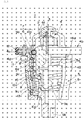
- Fig. 1 is a partial cross-sectional view of one configuration of the thermostat pertaining to the present invention
- Fig. 2 is a diagram showing a state in which the thermostat of Fig. 1 is installed in a housing
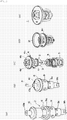
- Fig. 3 is an assembly process diagram of the thermostat of Fig. 1
- Fig. 4 is a diagram showing the actuation of the thermostat of Fig. 1 .
- the thermostat 1 shown in Fig. 1 is configured from a thermoelement 2 that actuates a valve based on detected changes in temperature of the cooling water, an upper frame 4 and lower frame 5 that cover the thermoelement 2, and a spring 8 which surrounds the thermoelement 2 and is arranged within the frames.
- the upper frame 4 and lower frame 5 are formed from an elastic material (for example, a material produced by the press-molding of a resin or a metal thin plate or the like).
- the thermoelement 2 comprises an element main body 10 made of metal with a built-in thermally-expanding body 13 that expands and contracts as a result of changes in temperature, and a piston 3 that protrudes from the upper end of the element main body 10 and slides up and down as a result of changes in the thermally-expanding body 13.
- the upper end of the piston 3 engages with an apex part inner-side surface 4f of the upper frame 4.
- thermoelement 2 An O-ring 6 is attached to the inner surface of the thermoelement 2, and a spring holder 9 made of resin that roughly covers the element main body 10 is attached therebelow.
- a stepped part 10a is formed in the perimeter edge of the element main body 10, the O-ring 6 being attached in such a way as to abut the stepped part 10a.
- a flanged spring-receiving part 9a that is pressure-contacted by one end of the spring 8 is formed in a spring holder 9 that covers the lower part of the element main body 10.
- the flanged valve 7 is configured from the stepped part 10a, the O-ring 6 and the spring-receiving part 9a.
- the width dimension of the spring-receiving part 9a of the spring holder 9 is formed to be substantially identical to the diameter dimension (diameter) of the O-ring 6.
- the O-ring 6 is fixed between the spring-receiving part 9a and the stepped part 10a by the elastic forces of the spring 8. Furthermore, when the element main body 10 and spring holder 9 are assembled, the inner-side surface of the spring holder 9 abuts against corner parts 10c, 10d formed in the perimeter of the element main body 10.
- the elastic forces of the spring 8 are not directly exerted on the O-ring 6 and, instead, the elastic forces on the O-ring 6 are uniformized by the spring-receiving part 9a to ensure the crush width of the O-ring 6 is constant and prevent non-uniform deformation of the O-ring 6.
- the O-ring 6 is not fixed to the element main body 10 by welding or annealing, it is fixed to the element main body 10 by the water pressure of the cooling water. This alleviates any fear of the O-ring 6 releasing from the element main body 10.
- cross-sectional shape of the O-ring 6 described in this embodiment and, for example, it may be rectangular in cross-section.
- a flange 4b that divides the housing roughly into two is formed in the upper frame 4.
- a protruding part 4c is formed along the entire perimeter of the perimeter edge of the flange 4b, and a rubber ring 12 for improving sealablity is attached to this protruding part 4c.
- a valve seat 4e that abuts against the upper side of the flanged valve 7 in the closed valve state is formed in the center of the flange 4b.
- the spring 8 is arranged so as to surround the thermoelement 2 and one end thereof elastically abuts against the rear side of the flanged valve 7, while the other end thereof pressure-contacts the base surface of the lower frame 5. Therefore, when the piston 3 is in the contracted state, the flanged valve 7 is pressure-attached against the valve seat 4e and closed by the elastic forces of the spring 8. On the other hand, the flanged valve 7 is separated from the valve seat 4e and opened by the expansion of the thermally-expanding body 13, the extension of the piston 3, and the pressing of the element main body 10 downward.
- the diameter (outer diameter) of the spring 8 is formed to be substantially identical to the diameter of the flanged valve 7, sliding discrepancies caused by tilting of the flanged valve 7 can be prevented and stable valve actuation is ensured.
- a plurality of latch frames 4a are formed in the lower surface of the flange 4b of the upper frame 4, and latch hooks 5a that latch to the latch frames 4a are formed in the lower frame 5.
- the upper frame 4 and lower frame 5 are integrally formed by the forming of the lower frame 5 from an elastic material and the utilizing of this elasticity to latch and fix the latch hooks 5a to the latch frames 4a.
- a plurality of communication holes 9c that allow contact of the cooling water against the element main body 10 are formed in the spring holder 9.
- the cooling water contacts the element main body 10 by way of the communication holes 9c which improves the temperature-sensitive precision of the thermoelement 2.
- a bypass valve 9b which, when actuated in the closed valve state by the flanged valve 7, allows cooling water to flow from the engine side into a bypass passage directly linked to the engine side and, when actuated in the opened valve state, which closes this bypass passage is formed in the spring holder 9.
- a hole 4d connecting from top to bottom is formed in the flange 4b, and a jiggle valve 11 whose function is to remove air bubbles is provided in this hole.
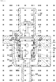
- Fig. 2(a) is a partial cross-sectional view of a thermostat 1 installed in a housing 30, and Fig. 2(b) is a plan view along A-A of Fig. 2(a) .
- the jiggle valve 11 has been omitted from Fig. 2(a) .
- a length dimension L of the latch hooks 5a formed in the lower frame 5 is larger than a gap dimension S1 between the lower frame 5 and inner wall of the housing 30.
- the length dimension L of the latch hooks 5a is less than a maximum gap dimension S2 between the spring 8 and lower frame 5.
- the forming of the latch hooks 5a in a prescribed length dimension in this way facilitates easier assembly of the thermostat 1 and prevents release of the latching between the upper frame 4 and lower frame 5 within the housing 30.
- the embodiment is not restricted to a configuration in which the latch hooks 5a are provided to project in the central axis direction of the thermostat 1 to latch from the outer side of the latch frames 4a as shown in this drawing, and a configuration in which the latch hooks 5a are provided to project outward from the thermostat 1 to latch from the inner side of the latch frames 4a may be adopted.
- the length dimension L of the latch hooks 5a described above be formed less than the maximum gap dimension S2 between the spring 8 and lower frame 5, the configuration is not restricted thereto. That is to say, the length dimension L of the latch hooks 5a may be larger than the maximum gap dimension S2.
- the latch hooks 5a utilizing the interval with the spring 8 formed in a spiral shape, can be latched from the inner side of the latch frames 4a, and the latching between the upper frame 4 and lower frame 5 is not easily released in this latched state.
- the latch frames 4a (four in the drawing) of the upper frame 4 are formed to avoid the position in which the jiggle valve 11 is provided in the flange 4b. That is to say, when one latch hook 5a of the lower frame 5 latches to a position in which it is in contact with the jiggle valve 11, the other latch hooks 5a abut against an upright-provided component 4g of the latch frames 4a but do not latch thereto.
- This configuration ensures that the upper and lower frame are correctly assembled and, in addition, that the jiggle valve 11 is reliably actuated free of the interference of the latch hooks 5a of the lower frame 5 on the jiggle valve 11.
- thermoelement 2 is configured by the introducing of a piston 3 into a piston hole 10b formed in the apex part of the element main body 10.
- an upper frame 4 is positioned to cover the thermoelement 2.
- a jiggle valve 11 is fitted and attached in advance into a hole 4d for the jiggle valve formed in a flange 4b of the upper frame 4.
- thermoelement 2 to which a spring holder 9 is attached is inserted into the inner side of the spring 8 and, furthermore, in a state in which a spring 8 is compressed by the lower side frame 5, the lower frame 5 latches with the upper frame 4.
- the thermostat 1 is completed by the fitting of a rubber ring 12 on to a protruding part 4c formed in the perimeter edge of the flange 4b of the upper frame 4 (Fig. 2(e)).
- the provision of the component parts from a constant direction as described above ensures that the steps for the assembly of the thermostat 1 can be easily implemented. Therefore, the assembly time can be shortened and the cost of the manufacturing equipment and the product itself can be reduced.
- the upper and lower frame are formed from an elastic material and are latched utilizing this elasticity, they can also be easily disassembled. Therefore, productivity is improved and, if it is determined through characteristic testing following assembly that the thermoelement is unsuitable, the frame can be easily disassembled in order to replace the element, and a uniformity of product characteristics can be easily achieved.
- the thermostat 1 shown in Figs. 4(a) and (b) is employed in a housing 30.
- a passage 31 for cooling water from the engine side, a passage 32 for cooling water to the radiator side, and a bypass passage 33 for cooling water to the engine side are respectively connected to the housing 30.
- the thermostat 1 is installed in the housing 30 so that the housing is roughly divided into top and bottom by a flange 4b of the upper frame 4. That is to say, the flange 4b blocks the radiator side passage 32 from the engine side passage 31 and bypass passage 33.
- the expansion change of the thermally-expanding body built into the thermoelement 2 is small when the temperature of the cooling water is less than a prescribed temperature and, as a result, the closed state of the flanged valve 7 is established as shown in Fig. 4(a) .
- the opened state of the bypass passage 33 and the closed state of the radiator side passage 32 is established by the bypass valve 9b at this time and, as a result, the cooling water flowing in from the engine side does not flow into the radiator side but instead is directly circulated to the engine side by way of the bypass passage 33.
- thermoelement 2 when the temperature of the cooling water is higher than a prescribed temperature, the piston 3 is extended as shown in Fig. 4(b) by the expansion change of the thermally-expanding body built into the thermoelement 2 and, as a result, the thermoelement 2 is pressed down to establish the opened state of the flanged valve 7. In addition, the bypass valve 9b is pressed downward at this time to establish the closed state of the bypass passage 33.
- the cooling water flowing in from the engine side flows to the radiator side whereupon, subsequent to the lowering of the temperature thereof in the radiator, it is circulated to the engine side.
- the thermostat 1 can be easily assembled and disassembled. For this reason, productivity is improved and, if it is determined through characteristic testing following assembly that the thermoelement is unsuitable, the frame can be easily disassembled in order to replace the element, and a uniformity of product characteristics can be easily achieved.
- the forming of the upper and lower frames 4, 5 from a material formed by the press-molding of, for example, a resin or metal thin plate reduces the weight and reduces the costs of the thermostat.
- the employing of an O-ring 6 in the flanged valve 7 produces lower manufacturing costs, easier assembly and better productivity by comparison with conventional thermostats based on the annealing of a rubber member.
- a spring-receiving part 9a is interposed between the O-ring 6 and a spring 8, the elastic forces of the spring 8 are not directly exerted on the O-ring 6 and, instead, the elastic forces on the O-ring 6 are uniformized by the spring-receiving part 9a to ensure the crush width of the O-ring 6 is always constant and prevent non-uniform deformation of the O-ring 6.
- the diameter (outer diameter) of the spring 8 is formed to be substantially identical to the diameter of the flanged valve 7 (spring-receiving part 9a), sliding discrepancies caused by tilting of the flanged valve 7 can be prevented to ensure stable valve actuation.
- the forming of the length of the latch hooks 5a for the latching of the upper frame 4 and lower frame 5 in a prescribed dimension prevents the release of the latched upper frame 4 and lower frame 5 in the housing 30.
- the latch frames 4a are formed avoiding the position in which the jiggle valve 11 is provided in the flange 4b, the latch hooks 5a of the lower frame 5 do not interfere with the jiggle valve 11.
- the lower frame 5 comprising at least the latch hooks 5a is formed from an elastic material (for example, a material formed by the press-molding of a resin or metal thin plate) it is able to be integrally formed with the upper frame 4 in the housing 30 as shown in Fig. 5 . That is to say, with the latch frames 4a integrally formed with the housing 30, the thermostat 1 can be assembled easily in the housing 30 utilizing the elasticity of the lower frame 5.
- an elastic material for example, a material formed by the press-molding of a resin or metal thin plate
- the present invention is suitable for employment in thermostats for variably controlling water temperature in, for example, a cooling water temperature control system for variably controlling the cooling water temperature of an internal combustion engine used in an automobile or the like.
Landscapes
- Engineering & Computer Science (AREA)
- General Engineering & Computer Science (AREA)
- Mechanical Engineering (AREA)
- Physics & Mathematics (AREA)
- Chemical & Material Sciences (AREA)
- Combustion & Propulsion (AREA)
- Fluid Mechanics (AREA)
- General Physics & Mathematics (AREA)
- Automation & Control Theory (AREA)
- Temperature-Responsive Valves (AREA)
Claims (6)
- Vorrichtung mit einem Thermostaten (1) und einem Gehäuse (30),
wobei der Thermostat (1) in dem Gehäuse (30) installiert ist, und wobei das Gehäuse (30) mit einer Vielzahl von Passagen (31, 32, 33) verbunden ist, durch die ein Kühlwasser strömt, wobei die Passagen durch die Betätigung eines Ventils (7) als Reaktion auf Temperaturänderungen des Kühlwassers miteinander verbunden oder blockiert werden,
wobei der Thermostat (1) aufweist: ein Thermoelement (2) mit einem Kolben (3), der als Ergebnis der Temperaturänderungen auf- und abgleitet, und einem Flanschventil (7) in seiner Außenkante, wobei das Flanschventil (7) durch die Vorschub- und Rückzugsbewegung des Kolbens (3) betätigt wird; eine Feder (8), die so angeordnet ist, dass sie das Thermoelement (2) umgibt und deren eines Ende die Rückseite des Flanschventils (7) elastisch druckkontaktiert; einen oberen Rahmen (4), in dem ein Ventilsitz ausgebildet ist, der an der Oberseite des Flanschventils (7) anliegt; und einen unteren Rahmen (5), der von dem anderen Ende der Feder (8) druckkontaktiert wird,
wobei in dem oberen Rahmen (4) Rastrahmen (4a) ausgebildet sind und im unteren Rahmen (5) mehrere Rasthaken (5a) ausgebildet sind, die an den Rastrahmen (4a) verrasten, wobei der obere Rahmen (4) und der untere Rahmen (5) integral ausgebildet sind, durch Bilden wenigstens des unteren Rahmens (5) aus einem elastischen Material und Verwendung der Elastizität, um die Rasthaken (5a) an den Rastrahmen (4a) zu verrasten und zu befestigen,
dadurch gekennzeichnet, dass in einem Zustand, in dem der obere Rahmen (4) und der untere Rahmen (5) verrastet sind, die Längenabmessung (L) der im unteren Rahmen (5) ausgebildeten Rasthaken (5a) größer als das Spaltmaß (Sl) zwischen dem unteren Rahmen (5) und der Innenwand des Gehäuses ist. - Thermostat nach Anspruch 1, dadurch gekennzeichnet, dass in dem oberen Rahmen (4) ein Rüttelventil (11) zum Entfernen von Luftblasen vorgesehen ist und, wenn einer der Rasthaken (5a) des unteren Rahmens (5) in einer Position in Kontakt mit dem Rüttelventil (11) des oberen Rahmens (4) verrastet ist, die anderen Rasthaken (5a) an den Rastrahmen (4a) anliegen, aber nicht daran verrastet sind.
- Thermostat nach Anspruch 1 oder 2, dadurch gekennzeichnet, dass das Thermoelement (2) einen Elementhauptkörper (10), in dem in dessen Außenkante ein gestufter Teil (10a) ausgebildet ist, und einen O-Ring (6) umfasst, der an der Außenfläche des Elementhauptkörpers (10) in einem am gestuften Teil (10a) anliegenden Zustand angebracht ist,
wobei das Flanschventil (7) aus wenigstens dem gestuften Teil (10a) und dem O-Ring (6) aufgebaut ist. - Thermostat nach Anspruch 1 oder 2, dadurch gekennzeichnet, dass das Thermoelement (2) ferner einen innerhalb der Feder (8) vorgesehenen Federhalter (9) aufweist, wobei der Federhalter (9) einen angeflanschten Federaufnahmeteil (9a) aufweist, an dem ein Ende der Feder (8) anliegt,
wobei das Flanschventil (7) aus dem gestuften Teil (10a), dem Federaufnahmeteil (9a) und dem zwischen dem gestuften Teil (10a) und dem Federaufnahmeteil (9a) vorgesehenen O-Ring (6) aufgebaut ist. - Thermostat nach Anspruch 1 oder 2, dadurch gekennzeichnet, dass die Breitenabmessung des Federaufnahmeteils (9a) des Federhalters (9) im Wesentlichen identisch mit der Durchmesserabmessung des O-Rings (6) ist.
- Thermostat nach Anspruch 4 oder 5, dadurch gekennzeichnet, dass in dem Federhalter (9) mehrere Verbindungslöcher (9c) ausgebildet sind, die einen Kontakt des Kühlwassers auf den Elementhauptkörper (10) ermöglichen.
Applications Claiming Priority (1)
| Application Number | Priority Date | Filing Date | Title |
|---|---|---|---|
| PCT/JP2004/017198 WO2006054347A1 (ja) | 2004-11-18 | 2004-11-18 | サーモスタット装置 |
Publications (3)
| Publication Number | Publication Date |
|---|---|
| EP1821018A1 EP1821018A1 (de) | 2007-08-22 |
| EP1821018A4 EP1821018A4 (de) | 2010-12-22 |
| EP1821018B1 true EP1821018B1 (de) | 2017-05-17 |
Family
ID=36406895
Family Applications (1)
| Application Number | Title | Priority Date | Filing Date |
|---|---|---|---|
| EP04822612.0A Expired - Lifetime EP1821018B1 (de) | 2004-11-18 | 2004-11-18 | Thermostatvorrichtung |
Country Status (5)
| Country | Link |
|---|---|
| EP (1) | EP1821018B1 (de) |
| KR (1) | KR101102110B1 (de) |
| CN (1) | CN100458251C (de) |
| ES (1) | ES2636975T3 (de) |
| WO (1) | WO2006054347A1 (de) |
Families Citing this family (5)
| Publication number | Priority date | Publication date | Assignee | Title |
|---|---|---|---|---|
| US7721973B2 (en) * | 2007-04-03 | 2010-05-25 | Dana Canada Corporation | Valve |
| CN101260824B (zh) * | 2007-12-05 | 2010-11-17 | 奇瑞汽车股份有限公司 | 调温器 |
| DE102010033564A1 (de) * | 2010-07-27 | 2012-02-02 | Behr Thermot-Tronik Gmbh | Thermostateinsatz |
| FR3024518B1 (fr) * | 2014-07-29 | 2016-09-02 | Vernet | Vanne thermostatique a manchon |
| WO2017164826A1 (en) * | 2016-03-24 | 2017-09-28 | Kirpart Otomotiv Parcalari Sanayi Ve Ticaret Anonim Sirketi | Unengaged lock system |
Family Cites Families (12)
| Publication number | Priority date | Publication date | Assignee | Title |
|---|---|---|---|---|
| DE2109326C3 (de) * | 1971-02-26 | 1974-05-02 | Behr-Thomson Dehnstoffregler Gmbh, 7014 Kornwestheim | Ventilsitzring eines thermostatischen Ventils, mit durchbruchloser Befestigung des unteren Widerlagers |
| DE9204611U1 (de) * | 1992-04-03 | 1993-08-05 | Behr-Thomson Dehnstoffregler Gmbh & Co, 70806 Kornwestheim | Deckel für ein Gehäusethermostat |
| JPH07224959A (ja) * | 1994-02-15 | 1995-08-22 | Toyota Motor Corp | 電磁弁のターミナル接続構造 |
| JP2932348B2 (ja) * | 1994-03-14 | 1999-08-09 | 日本サーモスタット株式会社 | サーモスタット |
| JP2786172B2 (ja) | 1996-07-03 | 1998-08-13 | 富士トムソン株式会社 | 自動車エンジン冷媒循環回路制御用熱応動弁 |
| CA2246462C (en) * | 1998-04-03 | 2004-05-11 | Yoshikazu Kuze | Cooling system for an automotive engine |
| JP3284407B2 (ja) * | 1999-01-27 | 2002-05-20 | 日本サーモスタット株式会社 | 冷却媒体の流れ制御方法およびその装置 |
| JP3582055B2 (ja) * | 1999-01-27 | 2004-10-27 | 日本サーモスタット株式会社 | サーモスタットの取り付け構造 |
| DE20023115U1 (de) * | 2000-04-14 | 2003-03-13 | Geiger Technik Gmbh, 82467 Garmisch-Partenkirchen | Thermostatisches Ventil |
| DE10032354B4 (de) * | 2000-07-04 | 2011-02-17 | Behr Thermot-Tronik Gmbh | Thermostatventil mit elektrisch beheizbarem Arbeitselement |
| JP4408539B2 (ja) * | 2000-07-25 | 2010-02-03 | 日本サーモスタット株式会社 | サーモスタットのケース構造 |
| KR20030067942A (ko) * | 2002-02-09 | 2003-08-19 | 현대자동차주식회사 | 가변제어방식의 전자식 서모스탯 |
-
2004
- 2004-11-18 EP EP04822612.0A patent/EP1821018B1/de not_active Expired - Lifetime
- 2004-11-18 CN CNB2004800420820A patent/CN100458251C/zh not_active Expired - Fee Related
- 2004-11-18 WO PCT/JP2004/017198 patent/WO2006054347A1/ja not_active Ceased
- 2004-11-18 ES ES04822612.0T patent/ES2636975T3/es not_active Expired - Lifetime
- 2004-11-18 KR KR1020067018439A patent/KR101102110B1/ko not_active Expired - Fee Related
Also Published As
| Publication number | Publication date |
|---|---|
| CN100458251C (zh) | 2009-02-04 |
| ES2636975T3 (es) | 2017-10-10 |
| KR20070096781A (ko) | 2007-10-02 |
| EP1821018A1 (de) | 2007-08-22 |
| KR101102110B1 (ko) | 2012-01-02 |
| EP1821018A4 (de) | 2010-12-22 |
| WO2006054347A1 (ja) | 2006-05-26 |
| CN1922426A (zh) | 2007-02-28 |
Similar Documents
| Publication | Publication Date | Title |
|---|---|---|
| US20010002646A1 (en) | Multifunction rocker switch | |
| EP2600046B1 (de) | Thermostat | |
| US7644731B2 (en) | Gas valve with resilient seat | |
| US20050168310A1 (en) | Electromagnetic valve | |
| CN100394126C (zh) | 膨胀阀 | |
| US8550371B2 (en) | Thermostatic assembly for fluid flow adjustment, and method making for such assembly | |
| KR20180111937A (ko) | 서모스탯 및 온도 제어 시스템 | |
| US4288033A (en) | Control valve assembly | |
| EP1821018B1 (de) | Thermostatvorrichtung | |
| US20050181647A1 (en) | Thermostat valve unit | |
| EP1860357B1 (de) | Sitzblock und ventilvorrichtung | |
| US20190271995A1 (en) | Thermostat assembly with position sensor | |
| US20040007629A1 (en) | Constructive arrangement applied to an integrated thermostatic valve attached to its own housing | |
| CA2269102A1 (en) | Engine coolant thermostat with overtemperature protection | |
| JP4396884B2 (ja) | サーモスタット装置 | |
| JP2006329272A (ja) | 弁装置 | |
| US4346837A (en) | Thermostat for controlling the flow of cooling water of an engine | |
| JP2004003541A (ja) | 弁装置用弁座部材および電磁制御弁 | |
| CN113167351A (zh) | 用于气体弹簧的温度补偿阀 | |
| EP2523065B1 (de) | Regulierklappe und Verfahren zur Kalibrierung der Regulierklappe | |
| JPH08177853A (ja) | 軸受およびその軸受を用いた流体制御バルブ | |
| JPS61197014A (ja) | オイルフイルタ | |
| US12025235B2 (en) | Pressure-reducing valve and method for manufacturing same | |
| JP2541494Y2 (ja) | 蒸気用減圧弁 | |
| US4382546A (en) | Temperature responsive valve device |
Legal Events
| Date | Code | Title | Description |
|---|---|---|---|
| PUAI | Public reference made under article 153(3) epc to a published international application that has entered the european phase |
Free format text: ORIGINAL CODE: 0009012 |
|
| 17P | Request for examination filed |
Effective date: 20070615 |
|
| AK | Designated contracting states |
Kind code of ref document: A1 Designated state(s): DE ES FR IT |
|
| R17P | Request for examination filed (corrected) |
Effective date: 20070615 |
|
| DAX | Request for extension of the european patent (deleted) | ||
| RBV | Designated contracting states (corrected) |
Designated state(s): DE ES FR IT |
|
| RBV | Designated contracting states (corrected) |
Designated state(s): DE ES FR IT |
|
| A4 | Supplementary search report drawn up and despatched |
Effective date: 20101122 |
|
| 17Q | First examination report despatched |
Effective date: 20111031 |
|
| GRAP | Despatch of communication of intention to grant a patent |
Free format text: ORIGINAL CODE: EPIDOSNIGR1 |
|
| INTG | Intention to grant announced |
Effective date: 20161128 |
|
| GRAS | Grant fee paid |
Free format text: ORIGINAL CODE: EPIDOSNIGR3 |
|
| GRAA | (expected) grant |
Free format text: ORIGINAL CODE: 0009210 |
|
| AK | Designated contracting states |
Kind code of ref document: B1 Designated state(s): DE ES FR IT |
|
| REG | Reference to a national code |
Ref country code: DE Ref legal event code: R096 Ref document number: 602004051285 Country of ref document: DE |
|
| REG | Reference to a national code |
Ref country code: ES Ref legal event code: FG2A Ref document number: 2636975 Country of ref document: ES Kind code of ref document: T3 Effective date: 20171010 |
|
| REG | Reference to a national code |
Ref country code: FR Ref legal event code: PLFP Year of fee payment: 14 |
|
| REG | Reference to a national code |
Ref country code: DE Ref legal event code: R097 Ref document number: 602004051285 Country of ref document: DE |
|
| PLBE | No opposition filed within time limit |
Free format text: ORIGINAL CODE: 0009261 |
|
| STAA | Information on the status of an ep patent application or granted ep patent |
Free format text: STATUS: NO OPPOSITION FILED WITHIN TIME LIMIT |
|
| 26N | No opposition filed |
Effective date: 20180220 |
|
| REG | Reference to a national code |
Ref country code: FR Ref legal event code: PLFP Year of fee payment: 15 |
|
| PGFP | Annual fee paid to national office [announced via postgrant information from national office to epo] |
Ref country code: SE Payment date: 20181210 Year of fee payment: 9 Ref country code: ES Payment date: 20181204 Year of fee payment: 15 |
|
| PG25 | Lapsed in a contracting state [announced via postgrant information from national office to epo] |
Ref country code: FR Free format text: LAPSE BECAUSE OF NON-PAYMENT OF DUE FEES Effective date: 20191130 |
|
| PGFP | Annual fee paid to national office [announced via postgrant information from national office to epo] |
Ref country code: IT Payment date: 20201013 Year of fee payment: 17 Ref country code: DE Payment date: 20201103 Year of fee payment: 17 |
|
| REG | Reference to a national code |
Ref country code: ES Ref legal event code: FD2A Effective date: 20210527 |
|
| PG25 | Lapsed in a contracting state [announced via postgrant information from national office to epo] |
Ref country code: ES Free format text: LAPSE BECAUSE OF NON-PAYMENT OF DUE FEES Effective date: 20191119 |
|
| REG | Reference to a national code |
Ref country code: DE Ref legal event code: R119 Ref document number: 602004051285 Country of ref document: DE |
|
| PG25 | Lapsed in a contracting state [announced via postgrant information from national office to epo] |
Ref country code: DE Free format text: LAPSE BECAUSE OF NON-PAYMENT OF DUE FEES Effective date: 20220601 |
|
| PG25 | Lapsed in a contracting state [announced via postgrant information from national office to epo] |
Ref country code: IT Free format text: LAPSE BECAUSE OF NON-PAYMENT OF DUE FEES Effective date: 20211118 |