EP1821133A1 - Assemblage de fixation de lunettes et de parasoleil en forme de plaque - Google Patents
Assemblage de fixation de lunettes et de parasoleil en forme de plaque Download PDFInfo
- Publication number
- EP1821133A1 EP1821133A1 EP06003149A EP06003149A EP1821133A1 EP 1821133 A1 EP1821133 A1 EP 1821133A1 EP 06003149 A EP06003149 A EP 06003149A EP 06003149 A EP06003149 A EP 06003149A EP 1821133 A1 EP1821133 A1 EP 1821133A1
- Authority
- EP
- European Patent Office
- Prior art keywords
- spectacles
- clip
- magnets
- sunshade
- pair
- Prior art date
- Legal status (The legal status is an assumption and is not a legal conclusion. Google has not performed a legal analysis and makes no representation as to the accuracy of the status listed.)
- Withdrawn
Links
Images



Classifications
-
- G—PHYSICS
- G02—OPTICS
- G02C—SPECTACLES; SUNGLASSES OR GOGGLES INSOFAR AS THEY HAVE THE SAME FEATURES AS SPECTACLES; CONTACT LENSES
- G02C9/00—Attaching auxiliary optical parts
-
- G—PHYSICS
- G02—OPTICS
- G02C—SPECTACLES; SUNGLASSES OR GOGGLES INSOFAR AS THEY HAVE THE SAME FEATURES AS SPECTACLES; CONTACT LENSES
- G02C2200/00—Generic mechanical aspects applicable to one or more of the groups G02C1/00 - G02C5/00 and G02C9/00 - G02C13/00 and their subgroups
- G02C2200/02—Magnetic means
Definitions
- the present invention relates to a plate-shaped spectacles and sunshade-clip assembly, and, more particularly, to a plate-shaped spectacles and sunshade-clip assembly in which a sunshade-clip is detachably attached to spectacles having a plate-shaped frame by use of magnets.
- the present invention aims to achieve an improved configuration to detachably attach the sunshade-clip to the spectacles by use of a plurality of magnets.
- a sunshade-clip which has the same shape as that of spectacles, is provided with a pair of arm members protruding from opposite ends thereof.
- the arm members of the sunshade-clip are configured to receive magnets, respectively, and the spectacles are provided with one or more magnets at positions corresponding to the magnets of the sunshade-clip.
- a frame of the spectacles has been fabricated by bending and welding a wire.
- the magnets to mount the magnets to the wire frame of the spectacles, it is necessary to provide specific positions of the wire frame with separate magnet housings or protruding arm members for receiving the magnets. Therefore, the wire frame of the spectacles has a problem of a complicated structure.
- the wire frame of the spectacles more particularly, lens frame positions of the wire frame, with such protruding magnet receiving members causes deterioration in the outer appearance of the spectacles, and also causes an inconvenience in use or storage, for example, the protruding magnet receiving members may become caught on clothing when stored in pockets.
- the present invention has been made in view of the above problems, and it is an object of the present invention to provide a plate-shaped spectacles and sunshade-clip assembly wherein magnets, which are used to detachably attach a plate-shaped spectacles to a sunshade-clip having a shape corresponding to that of the spectacles, can be hidden as much as possible in their assembled state, and the shape of the sunshade-clip can be selected within a wider range, whereby an improved outer appearance and convenient use of the spectacles and sunshade-clip assembly can be accomplished.
- both spectacles and sunshade-clip are articles having symmetrical left and right sides, and thus, only one side will be designated by reference numerals and explained.
- spectacles 1 according to the present embodiment include a spectacles frame 2 having a plate shape suitable for achieving the object of the present invention. More particularly, the plate-shaped spectacles frame 2 is fabricated via a press process and laser cutting using a metal or plastic plate or an injection molding, differently from the previously described conventional spectacles frame fabricated by bending and welding a wire.
- the spectacles frame 2 is divided into a lens frame portion 4 for receiving a pair of prescription lenses 3, and a nose bridge portion 5, which are integrally formed with each other by processing a single plate.
- a pair of hinge units 6 may be integrally formed with the spectacles frame 2.
- the hinge units 6 may be separately fabricated and fixed to opposite ends of the lens frame portion 4 via welding. In both cases, the manufacturing process of the spectacles frame 2 can be greatly simplified as compared to the prior art, and the resulting spectacles frame 2 provides the spectacles 1 with an improved plate-shaped outer appearance.
- the spectacles frame 2 is provided, at an upper end of a rear surface thereof, with a pair of magnet holders H, such that spectacles magnets Ms are inserted into the magnet holders H, respectively.
- a sunshade-clip 50 usable with the spectacles 1 having the above-described configuration includes a plate-shaped integral clip frame 51, which is made of a metal or plastic material.
- the clip frame 51 is provided with a pair of magnet arms 52, which protrude rearward from an upper end of the clip frame 51 at positions corresponding to the magnet holders H of the spectacles 1.
- Clip magnets Mc corresponding to the spectacles magnets Ms are inserted into the magnet arms 52, respectively.
- the sunshade-clip 50 is able to be detachably attached to the spectacles 1 by use of both the spectacles magnets Ms and the clip magnets Mc, to form the spectacles and sunshade-clip assembly.
- the resulting spectacles and sunshade-clip assembly exhibits an improved outer appearance with a minimum protruding region.
- FIG. 2 illustrates an alternative configuration of the above described first embodiment.
- the spectacles 1 is provided, at the upper end of the rear surface thereof, with a fitting hook HK, such that the spectacles magnet Ms is inserted into a fitting space defined in the fitting hook HK from the rear side of the spectacles 1. Accordingly, the spectacles magnet Ms is not exposed to the front side of the spectacles 1.
- the clip frame 51 of the sunshade-clip 50 is provided with a downwardly bent magnet arm 52'.
- the magnet arm 52' is used to receive the clip magnet Mc inserted therein, and protrudes rearward from the upper end of the clip frame 51.
- the magnet arm 52' is provided with a hinge bar 60 and a holding bar 61.
- the holding bar 61 extends forward from a distal end of the magnet arm 52' such that it is located in front of the clip magnet Mc.
- the holding bar 61 serves to allow the clip frame 51 of the sunshade-clip 50 to be mechanically caught by the spectacles frame 2 of the spectacles 1.
- the sunshade-clip 50 is able to be attached to the spectacles 1 by use of a magnetic attraction force and mechanical coupling force obtained from the spectacles magnet Ms and the fitting hook HK of the spectacles 1 and the clip magnet Mc and the holding bar 61 of the sunshade-clip 50. Furthermore, the sunshade-clip 50 is pivotally rotatable upward and downward about the hinge bar 60, and therefore, is able to be easily opened away from the spectacles 1 after being attached to the spectacles 1.
- FIG. 3 illustrates various mounting positions of spectacles magnets.
- the spectacles magnets Ms1, Ms2, Ms3, Ms4, Ms5, Ms6, Ms7, Ms8.. may be selectively mounted to various positions of the spectacles frame 2 of the spectacles 1.
- clip magnets may be selectively mounted to various positions of the clip frame of the sunshade clip.
- FIGS. 4 to 6 illustrate the advantage of the plate-shaped spectacles frame 2 of the spectacles 1. That is, when the spectacles frame 2 has a plate shape rather than a prior art wire frame, the spectacles magnet Ms may have a shape freely selected from among various shapes so long as it can be inserted into the spectacles frame 2 of the spectacles 1. This is possible due to the fact that the spectacles frame 2 is made of a thin metal or plastic plate.
- the spectacles magnet Ms may be inserted through the spectacles frame 2 as shown in FIG. 4, may be inserted to be exposed to the outside only from a front side of the spectacles frame 2 as shown in FIG. 5, or may be inserted to be exposed to the outside only from a rear side of the spectacles frame 2 as shown in FIG. 6. Accordingly, if necessary, the spectacles magnet Ms can be mounted so as not to reveal itself in front of a wearer.
- FIG. 7 illustrates a plate-shaped spectacles and sunshade-clip assembly according to a second embodiment of the present invention, which is based on the same technical idea as that of the above-described first embodiment.
- spectacles 100 include a spectacles frame 102, which is obtained by processing a plate similar to the first embodiment, but has a modified shape.
- a pair of hinge legs 106 are integrally formed with the spectacles frame 102 such that they are bent rearward from opposite ends of the spectacles frame 102.
- a pair of temple arms 120 are hingedly connected to the hinge legs 106.
- Each of the temple arms 120 is provided with an attachment piece 110, which is made of one selected from among various magnetic materials including a soft magnet.
- a sunshade-clip 150 of the second embodiment, for use with the spectacles 100 may have a shape selected from among various shapes.
- the sunshade-clip 150 includes a pair of colored lenses 153 and 154 which are formed via an injection molding or plate cutting, and a clip bridge 155 to connect the colored lenses 153 and 154 to each other.
- a pair of bent clip legs 156 may be integrally formed with the colored lenses 153 and 154, respectively, or may be previously fabricated and fixed to the colored lenses 153 and 154 as shown in FIG. 7.
- the clip legs 156 have the same contour as the hinge legs 106 of the spectacles 100.
- a pair of upper and lower clip magnets Mc1 and Mc2 are fixed to each of the clip legs 156 of the sunshade-clip 150, such that they are attached to an associated one of the attachment pieces 110 of the spectacles 100.
- the sunshade-clip 150 is able to be selectably assembled to the spectacles 100 as the clip magnets Mc1 and Mc2 are attached to and detached from the attachment pieces 110.
- the clip magnets Mc1 and Mc2 are attached to the attachment pieces. 110, no magnets protrude from the resulting spectacles and sunshade-clip assembly, whereby an improved outer appearance of the assembly can be accomplished.
- the clip magnets Mc1 and Mc2 are easily detachable from the attachment pieces 100 by simply folding the temple arms 120 of the spectacles 100, the spectacles and sunshade-clip assembly has an advantage of a convenient separation.
- FIG. 8 illustrates a first alternative configuration of the second embodiment of FIG. 7.
- the first alternative configuration is similar to the second embodiment except for that attachment pieces 111 are attached to the hinge legs 106 of the spectacles 100 rather than being attached to the temple arms 120 hingedly connected to the hinge legs 106.
- FIG. 9 illustrates a second alternative configuration of the second embodiment of FIG. 7.
- a pair of spectacles magnets Ms1 and Ms2 are inserted into a rear surface of each of the hinge legs 106 of the spectacles 100 in a manner selected from among various mounting manners as shown in FIGS. 4 to 6, such that the spectacles magnets Ms1 and Ms2 correspond to the clip magnets Mc1 and Mc2.
- FIG. 10 illustrates a third alternative configuration of the second embodiment of FIG. 7.
- a pair of spectacles magnets Ms are inserted into an upper end of the spectacles frame 102 of the spectacles 100 in a manner selected from among various methods as shown in FIGS. 4 to 6.
- the sunshade-clip 150 for use with the spectacles 100 includes the pair of colored lenses 153 and 154 formed via an injection molding or plate cutting, the clip bridge 155 to connect the colored lenses 153 and 154 to each other, and a pair of clip hooks 157 fixed to upper ends of the colored lenses 153 and 154 to protrude rearward, respectively.
- each of the clip hooks 157 has a dimension slightly greater than a thickness of the spectacles frame 102.
- a pair of clip magnets Mc are inserted into clip hook pieces 157' of the pair of the clip hooks 157.
- the sunshade-clip 150 is able to be detachably attached to the spectacles 100 as the clip hooks 157 are mechanically caught by the spectacles frame 102 and the clip magnets Mc are attached to the spectacles magnets Ms.
- FIG. 11 is a rear perspective view of FIG. 10.
- the circle of FIG. 11 illustrates an alternative configuration of FIG. 10 wherein the spectacles magnet Ms takes the form of an elongated bent magnetic plate.
- the spectacles magnet Ms having the above configuration is advantages since it has a function of guiding the positioning and attachment of the clip magnet Mc.
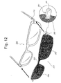
- FIG. 12 illustrates a third embodiment of the present invention.
- a pair of hinge legs 210 of a spectacles frame are separately fabricated and attached to spectacles 200 having a plate shape.
- a sunshade-clip 250 for use with the spectacles 200 includes a pair of colored lenses 253 and 254 and a clip bridge 255, which are integrally formed via an injection molding or plate cutting.
- a pair of clip holders 260 are fixed to opposite ends of the colored lenses 253 and 254, such that clip magnets Mc are inserted into the clip holders 260, respectively, to be exposed to the rear side of the sunshade-clip 250.
- each of the clip holders 260 is integrally formed with a holding piece 261.
- the hinge legs 210 of the spectacles 200 may be made of a magnetic material attractable by the clip magnet Mc, so as to eliminate the need of a magnet.
- a spectacles magnet Ms may be inserted into a rear surface of each of the hinge leg 210 in a manner selected from among various mounting manners as shown in FIGS. 4 to 6, such that it is detachably attached to the clip magnet Mc.
- the present invention provides a spectacles and sunshade-clip assembly in which magnets, which are used to detachably attach a sunshade-clip to spectacles, can be hidden as much as possible in their assembled state, and the shape of the sunshade-clip can be selected within a wider range.
Landscapes
- Physics & Mathematics (AREA)
- Health & Medical Sciences (AREA)
- General Physics & Mathematics (AREA)
- Ophthalmology & Optometry (AREA)
- Optics & Photonics (AREA)
- Eyeglasses (AREA)
Priority Applications (1)
| Application Number | Priority Date | Filing Date | Title |
|---|---|---|---|
| EP06003149A EP1821133A1 (fr) | 2006-02-16 | 2006-02-16 | Assemblage de fixation de lunettes et de parasoleil en forme de plaque |
Applications Claiming Priority (1)
| Application Number | Priority Date | Filing Date | Title |
|---|---|---|---|
| EP06003149A EP1821133A1 (fr) | 2006-02-16 | 2006-02-16 | Assemblage de fixation de lunettes et de parasoleil en forme de plaque |
Publications (1)
| Publication Number | Publication Date |
|---|---|
| EP1821133A1 true EP1821133A1 (fr) | 2007-08-22 |
Family
ID=36644312
Family Applications (1)
| Application Number | Title | Priority Date | Filing Date |
|---|---|---|---|
| EP06003149A Withdrawn EP1821133A1 (fr) | 2006-02-16 | 2006-02-16 | Assemblage de fixation de lunettes et de parasoleil en forme de plaque |
Country Status (1)
| Country | Link |
|---|---|
| EP (1) | EP1821133A1 (fr) |
Cited By (1)
| Publication number | Priority date | Publication date | Assignee | Title |
|---|---|---|---|---|
| CN106950715A (zh) * | 2017-04-13 | 2017-07-14 | 林建克 | 带磁铁的眼镜 |
Citations (6)
| Publication number | Priority date | Publication date | Assignee | Title |
|---|---|---|---|---|
| US6120144A (en) * | 1999-02-11 | 2000-09-19 | Sae Myung Industrial Co. | Glasses with an upper pair of glasses attached to a lower pair of glasses |
| US20020012097A1 (en) * | 1998-11-02 | 2002-01-31 | Gary M. Zelman | Auxiliary eyewear attachment methods and apparatus |
| US6783238B1 (en) * | 2003-06-11 | 2004-08-31 | Arts Optical Co., Ltd. | Method for magnetically connecting accessories to eyeglasses |
| US20050001976A1 (en) * | 2003-07-03 | 2005-01-06 | Chao David Yinkai | Eyeglass device |
| US20050012892A1 (en) * | 2003-07-14 | 2005-01-20 | Hun-Yang Park | Eyeglasses assembly including main eyeglasses and auxiliary eyeglasses combined with each other via connection bar |
| US20050151922A1 (en) * | 2003-12-24 | 2005-07-14 | Nonu Ifergan | Eyeglasses with living hinge |
-
2006
- 2006-02-16 EP EP06003149A patent/EP1821133A1/fr not_active Withdrawn
Patent Citations (6)
| Publication number | Priority date | Publication date | Assignee | Title |
|---|---|---|---|---|
| US20020012097A1 (en) * | 1998-11-02 | 2002-01-31 | Gary M. Zelman | Auxiliary eyewear attachment methods and apparatus |
| US6120144A (en) * | 1999-02-11 | 2000-09-19 | Sae Myung Industrial Co. | Glasses with an upper pair of glasses attached to a lower pair of glasses |
| US6783238B1 (en) * | 2003-06-11 | 2004-08-31 | Arts Optical Co., Ltd. | Method for magnetically connecting accessories to eyeglasses |
| US20050001976A1 (en) * | 2003-07-03 | 2005-01-06 | Chao David Yinkai | Eyeglass device |
| US20050012892A1 (en) * | 2003-07-14 | 2005-01-20 | Hun-Yang Park | Eyeglasses assembly including main eyeglasses and auxiliary eyeglasses combined with each other via connection bar |
| US20050151922A1 (en) * | 2003-12-24 | 2005-07-14 | Nonu Ifergan | Eyeglasses with living hinge |
Cited By (2)
| Publication number | Priority date | Publication date | Assignee | Title |
|---|---|---|---|---|
| CN106950715A (zh) * | 2017-04-13 | 2017-07-14 | 林建克 | 带磁铁的眼镜 |
| CN106950715B (zh) * | 2017-04-13 | 2023-08-08 | 温州益泰光学眼镜有限公司 | 带磁铁的眼镜 |
Similar Documents
| Publication | Publication Date | Title |
|---|---|---|
| US20070273823A1 (en) | Spectacles and ornament assembly | |
| US7520605B1 (en) | Eyewear with magnetic connection between lenses and frame | |
| US20060187404A1 (en) | Eyeglasses with interchangeable decorative attachments | |
| US4988181A (en) | Ornamental device for eyeglasses | |
| WO2006028954A1 (fr) | Ensemble lunettes comprenant un ensemble monture et lentilles auxiliaire | |
| US5585870A (en) | Rimless spectacles with its lenses supported and clipped at three points | |
| CN100510848C (zh) | 辅助眼镜的安装方法及装置 | |
| JP2006113549A (ja) | 眼鏡装飾物品及びこの眼鏡装飾物品を備えた眼鏡 | |
| US7275820B2 (en) | Spectacles and sunshade clip assembly using magnets | |
| TW412654B (en) | Method to produce attachable lens for spectacles | |
| JP6212540B2 (ja) | 装飾用部品を備える眼鏡フレーム | |
| US10302969B2 (en) | Eyeglass system and method of engagement | |
| US20070236652A1 (en) | Plate-shaped spectacles and sunshade-clip assembly | |
| US6345892B2 (en) | Sunglasses with readily detachable lens | |
| JP5143296B2 (ja) | 眼鏡用のレンズ連結具及びレンズ交換可能の眼鏡並びにレンズ形成基材 | |
| US7014313B1 (en) | Interchangeable spectacles and sunshade clip assembly | |
| US20070236653A1 (en) | Interchangeable spectacles and clip-on assembly | |
| US10962800B1 (en) | Reconfigurable eyewear system | |
| US20060290881A1 (en) | Spectacles set with magnetic clips and detachable magnetic auxiliary frame | |
| CN209931735U (zh) | 一种证件卡套 | |
| US7175272B2 (en) | Spectacles and sunshade clip assembly using magnets | |
| US20050206835A1 (en) | Spectacle assembly | |
| JP3052031U (ja) | 簡易メガネ | |
| JP2003532929A (ja) | 異なる湾曲のフレーム及び交換可能なつるを有するめがねファミリー | |
| JP2983213B1 (ja) | メガネ付加レンズの製造方法 |
Legal Events
| Date | Code | Title | Description |
|---|---|---|---|
| PUAI | Public reference made under article 153(3) epc to a published international application that has entered the european phase |
Free format text: ORIGINAL CODE: 0009012 |
|
| AK | Designated contracting states |
Kind code of ref document: A1 Designated state(s): AT BE BG CH CY CZ DE DK EE ES FI FR GB GR HU IE IS IT LI LT LU LV MC NL PL PT RO SE SI SK TR |
|
| AX | Request for extension of the european patent |
Extension state: AL BA HR MK YU |
|
| AKX | Designation fees paid | ||
| STAA | Information on the status of an ep patent application or granted ep patent |
Free format text: STATUS: THE APPLICATION IS DEEMED TO BE WITHDRAWN |
|
| 18D | Application deemed to be withdrawn |
Effective date: 20080223 |
|
| REG | Reference to a national code |
Ref country code: DE Ref legal event code: 8566 |