EP1821180A1 - Dispositif de pointage pour utilisateur tel qu'une souris - Google Patents
Dispositif de pointage pour utilisateur tel qu'une souris Download PDFInfo
- Publication number
- EP1821180A1 EP1821180A1 EP05028777A EP05028777A EP1821180A1 EP 1821180 A1 EP1821180 A1 EP 1821180A1 EP 05028777 A EP05028777 A EP 05028777A EP 05028777 A EP05028777 A EP 05028777A EP 1821180 A1 EP1821180 A1 EP 1821180A1
- Authority
- EP
- European Patent Office
- Prior art keywords
- ball
- electric appliance
- circuits
- electrical components
- data
- Prior art date
- Legal status (The legal status is an assumption and is not a legal conclusion. Google has not performed a legal analysis and makes no representation as to the accuracy of the status listed.)
- Withdrawn
Links
Images

Classifications
-
- G—PHYSICS
- G06—COMPUTING OR CALCULATING; COUNTING
- G06F—ELECTRIC DIGITAL DATA PROCESSING
- G06F3/00—Input arrangements for transferring data to be processed into a form capable of being handled by the computer; Output arrangements for transferring data from processing unit to output unit, e.g. interface arrangements
- G06F3/01—Input arrangements or combined input and output arrangements for interaction between user and computer
- G06F3/03—Arrangements for converting the position or the displacement of a member into a coded form
- G06F3/033—Pointing devices displaced or positioned by the user, e.g. mice, trackballs, pens or joysticks; Accessories therefor
- G06F3/0354—Pointing devices displaced or positioned by the user, e.g. mice, trackballs, pens or joysticks; Accessories therefor with detection of two-dimensional [2D] relative movements between the device, or an operating part thereof, and a plane or surface, e.g. 2D mice, trackballs, pens or pucks
-
- G—PHYSICS
- G06—COMPUTING OR CALCULATING; COUNTING
- G06F—ELECTRIC DIGITAL DATA PROCESSING
- G06F3/00—Input arrangements for transferring data to be processed into a form capable of being handled by the computer; Output arrangements for transferring data from processing unit to output unit, e.g. interface arrangements
- G06F3/01—Input arrangements or combined input and output arrangements for interaction between user and computer
- G06F3/03—Arrangements for converting the position or the displacement of a member into a coded form
- G06F3/033—Pointing devices displaced or positioned by the user, e.g. mice, trackballs, pens or joysticks; Accessories therefor
- G06F3/0354—Pointing devices displaced or positioned by the user, e.g. mice, trackballs, pens or joysticks; Accessories therefor with detection of two-dimensional [2D] relative movements between the device, or an operating part thereof, and a plane or surface, e.g. 2D mice, trackballs, pens or pucks
- G06F3/03543—Mice or pucks
-
- G—PHYSICS
- G06—COMPUTING OR CALCULATING; COUNTING
- G06F—ELECTRIC DIGITAL DATA PROCESSING
- G06F3/00—Input arrangements for transferring data to be processed into a form capable of being handled by the computer; Output arrangements for transferring data from processing unit to output unit, e.g. interface arrangements
- G06F3/01—Input arrangements or combined input and output arrangements for interaction between user and computer
- G06F3/03—Arrangements for converting the position or the displacement of a member into a coded form
- G06F3/033—Pointing devices displaced or positioned by the user, e.g. mice, trackballs, pens or joysticks; Accessories therefor
- G06F3/0354—Pointing devices displaced or positioned by the user, e.g. mice, trackballs, pens or joysticks; Accessories therefor with detection of two-dimensional [2D] relative movements between the device, or an operating part thereof, and a plane or surface, e.g. 2D mice, trackballs, pens or pucks
- G06F3/03549—Trackballs
-
- G—PHYSICS
- G06—COMPUTING OR CALCULATING; COUNTING
- G06F—ELECTRIC DIGITAL DATA PROCESSING
- G06F3/00—Input arrangements for transferring data to be processed into a form capable of being handled by the computer; Output arrangements for transferring data from processing unit to output unit, e.g. interface arrangements
- G06F3/01—Input arrangements or combined input and output arrangements for interaction between user and computer
- G06F3/048—Interaction techniques based on graphical user interfaces [GUI]
- G06F3/0484—Interaction techniques based on graphical user interfaces [GUI] for the control of specific functions or operations, e.g. selecting or manipulating an object, an image or a displayed text element, setting a parameter value or selecting a range
- G06F3/0485—Scrolling or panning
-
- G—PHYSICS
- G06—COMPUTING OR CALCULATING; COUNTING
- G06F—ELECTRIC DIGITAL DATA PROCESSING
- G06F3/00—Input arrangements for transferring data to be processed into a form capable of being handled by the computer; Output arrangements for transferring data from processing unit to output unit, e.g. interface arrangements
- G06F3/01—Input arrangements or combined input and output arrangements for interaction between user and computer
- G06F3/048—Interaction techniques based on graphical user interfaces [GUI]
- G06F3/0484—Interaction techniques based on graphical user interfaces [GUI] for the control of specific functions or operations, e.g. selecting or manipulating an object, an image or a displayed text element, setting a parameter value or selecting a range
- G06F3/0486—Drag-and-drop
Definitions
- the present invention relates to a user operable device for control of or communication with an electric appliance, in particular to a user operable pointing device such as a mouse.
- the electric appliance may be a computer, PDA, mobile phone, GPS device, game device, television set, car entertainment system or personal exercise monitoring device, for example.
- One of the most common interfaces between a user and a computer or a computer controlled device is a conventional mouse detecting 2D movements of the mouse on a suitable flat surface and providing corresponding signals to a computer for moving a pointer on a display.
- a conventional mouse includes buttons for positioning a pointer, selecting data, opening and closing windows or menus for further selections, starting and closing programs or applications and entering commands in various situations.
- a computer mouse may include other functions, e.g. the scrolling function which is often realised by means of a scrolling wheel.
- a mechanical mouse includes a ball inside the mouse frame, the ball being rolled on a flat surface and its movements being detected by sensors outside the ball.
- the technology is normally opto-mechanical or fully optical.
- an optical sensor is monitoring microscopic features of a suitable surface to register motions of the mouse. The surface is lit with a LED, for example, and the sensor takes and compares successive images of the surface to detect the motions.
- mice During recent years, also wireless technology have been applied to mice. In a widely used technology, a low-power, low-speed wireless link is formed between a mouse and a USB unit connected to a host computer.
- Bluetooth technology is becoming a standard for wireless communication between electric devices. Bluetooth adapters connectable to USB connectors, for example, are available. Also computers and other electric devices with an integrated Bluetooth interface are available and this is becoming a standard solution, too. Accordingly, also mice provided with a Bluetooth interface are already available.
- An object of the invention is to present a user operable device for control of or communication with an electric appliance, in particular a user operable pointing device such as a mouse, which to large extent solves the above mentioned problems.
- a user operable device for control of or communication with an electric appliance in particular a user operable pointing device such as a mouse, comprising electrical components and circuits including sensor means, processing means and wireless communication means for detecting movements including at least rotational movements of the device, producing data related to said movements and transmitting said data to the electric appliance, is characterised in that which is defined in the characterising part of claim 1.
- Claims 2 to 8 define various embodiments of the user operable device of the invention.
- a user interface for control of or communication with an electric appliance comprising a user operable device including sensor means, processing means and wireless communication means for detecting movements including at least rotational movements of the device, producing data related to said movements and transmitting said data to the electric appliance, is characterised in that which is defined in the characterising part of claim 9.
- Claims 10 to 13 define various embodiments of the user interface of the invention.
- the device of the invention is very cheap to manufacture.
- the mechanics of the device is very simple and durable.
- the ball shape is ideal in rigidity versus weight.
- the device of the invention is basically a Bluetooth enabled versatile sensor package which may have many other applications as a user operable control or communication device.
- a user operable device 1 presented in Figs. 1 to 4 is essentially a ball 2 including an outer surface 2' for free rolling and for receiving influences of physical effects on the surface and the device.
- the device e.g. a user operable pointing device such as a mouse, comprises electrical components and circuits including sensor means 3, 4, 5, processing means 7 and wireless communication means 8 for detecting movements including at least rotational movements of the device, producing data related to said movements and transmitting said data to an electric appliance for control of or communication with the appliance.
- the device 1 is an independently operating ball shaped device having necessary physical properties and sensors and electrical components and circuits inside the ball 1 in integrated relationship with the ball, so that the ball as such works as a user operable device for control of or communication with electric appliances.
- the device 1 of Figs. 1 to 4 includes inside the ball 2 various sensors including accelerometers 3, magnetic field sensors 4 and pressure sensors 5.
- the accelerometers 3 may include e.g. a 3-axis MEMS accelerometer.
- the magnetic field sensors 4 include three low power single axis magnetometers 4a, 4b and 4c, which may be e.g. low cost fluxgate magnetometers.
- the pressure sensors 5 may be miniature piezoresistive sensors, for example.
- Sensor components may include also electronics for giving digital sensor outputs, and various other electronic circuits may be necessary for converting the sensor outputs into digital data for further processing and utilisation.
- the necessary ADC circuitry and other electronic circuits for processing the sensor outputs are presented here as a one unit 6.
- the central processing unit 7 includes a suitable processor with necessary memories for saving programs and data.
- the programs provide, for example, necessary filtering functions for processing the sensor data for separating the essential data from noise and calculation functions for obtaining the desired data from the sensor data related to motions, pressure changes or other physical effects detected by the sensors.
- the link between the device 1 and the electric appliance in connection with which it is used is wireless.
- An advantageous technology for realising the link is Bluetooth, and accordingly the exemplary device of Figs 1 to 4 includes a suitable Bluetooth chipset 8.
- the device of Figs. 1 to 4 includes a rechargeable battery 9 and necessary power management circuits 10.
- the ball 2 is a hollow ball provided with a strongly built, thick enough and suitably flexible spherical jacket 11. It may be made of suitable rubber or plastic material and may include originally two halves which are after the assembly of the inside components and circuits attached to each other by gluing, for example.
- the components have been assembled on a printed circuit board 13, the magnetic field sensors 4a and 4b being attached on an auxiliary printed circuit board 14 connected as a single-in-line unit on the board 13.
- the battery 9 is attached mechanically and electrically on the other side of the printed circuit board 13 by means of terminal plates or springs 15 and 16.
- the spherical jacket 11 is provided with a hole 17 which is in alignment with an inner charging connector 18 which is connected to the terminals of the battery by means of leads 19 and 20.
- the hollow space inside the jacket is filled with suitable filler material 12, e.g. plastic foam material.
- suitable filler material 12 e.g. plastic foam material.
- a primary use of the device of the invention is a user operable pointing device such as a mouse.
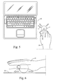
- Fig. 5 presents a laptop computer 22 including a display and functions for controlling the computer by a computer mouse or similar device. Such functions for controlling include e.g. cursor and scrolling functions.
- the ball device 1 according to the invention is used as a mouse.
- the user 21 uses the ball 1 by moving it with a finger 22, and the ball sends mouse control data produced by moving and selectively pressing the ball via a wireless link L.
- the ball may be controlled also by means of the palm of the hand 21 on a suitable surface 23, as in Fig. 6.
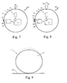
- Figs. 7 and 8 present schematically one possible way of realising some mouse button functions in the device of the invention.
- a quite light push P1 on the surface 2' of the ball device 1 causes a pressure inside the ball which is relative to the strength of the push.
- the pressure sensor 5 detects it and gives a correspnding signal to the processor 7.
- the device includes also an amplifier 24 and a transducer 25 attached to the jacket 11 of the ball device.
- the processor controls the amplifier 24 and the transducer to produce a haptic feedback F1, a short low energy vibration pulse.
- the ball 1 sends a corresponding control signal S1 to the controlled device, e.g. a computer, meaning a click of the left button of the mouse, for example.
- the push P2 is stronger.
- the processor 7 controls the device to send a corresponding control signal S2 meaning a click of the right button of the mouse, for example, and to give a corresponding stronger haptic feedback F3.
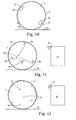
- Figs. 10 to 12 present schematically some further examples of sensor arrangements which may be used for detecting the rotational and other movements of the device.
- the device 2 includes miniature video cameras 26 to picture the environment through suitable windows 27 in the surface 2' of the ball.
- the speed and direction of a rotational movement R of the ball may be determined by processing the picture data given by the cameras.
- a RF transmitter 31 e.g. a Bluetooth transmitter
- an electric appliance 30 e.g. a computer
- an electric appliance 30 e.g. a computer
- an electric appliance 30 e.g. a computer
- an electric appliance 30 e.g. a computer
- an electric appliance 30 e.g. a computer
- an electric appliance 30 e.g. a computer
- an electric appliance 30 e.g. a computer
- the position of the ball may be calculated from the time differences in receiving a signal from the transmitter 31 to different antennas 28, and by analysing the sequences of the ball positions the movements of the ball may be obtained.
- a light transmitter 33 e.g. a suitable LED
- an electric appliance 32 e.g. a computer
- several light receptors 34 behind small windows or for the light of the transmitter 33 transparent surface 2' of the ball.
- the position of the ball may be calculated from the time differences in receiving a light signal from the transmitter 33 to different receptors 34, and by analysing the sequences of the ball positions, the movements of the ball may be obtained.
- Step 1 The CPU 7 opens or otherwise establishes a communication channel to the electric appliance to be controlled.
- the appliance may be a computer, mobile phone, PDA, data projector, toy, TV set, car, for example. Step 1 may be skipped the appliance or the used communication method does not require initialisation.
- Step 2 The CPU 7 establishes reference direction of the movement of the ball device. It can be done via a user input by shortly rotating the apparatus to a pre-determined direction or by placing the apparatus on a certain "start orientation" where some visible clues of the orientation of the ball are viewed by the user, for example.
- Step 3 The CPU 7 reads sensor data obtained from the sensors 3, 4 and 5.
- Step 4 The CPU 7 performs the necessary filtering functions to process the sensor data for separating the essential data from noise.
- Step 5 The CPU 7 calculates the movement values of the ball device from the essential sensor data. This is done by converting accelerometer and magnetic field orientation values into a motion and rotational co-ordinates of the device. These co-ordinates are converted to mouse movement co-ordinates, for example.
- Step 6 The CPU 7 calculates the pressure from the pressure sensor data and determines if the user wished to activate or deactivate a corresponding function, e.g. a mouse button function.
- Step 7 The CPU 7 sends the calculated ball device movement values and other function values, e.g. status values, via the communication channel to the receiving electric appliance.
- Step 8 Loop back to step 3.
- the user operable device of the invention may work as a device corresponding to a conventional computer mouse in an interface between a computer or computer controlled electric appliance and a user.
- the ball device needs then a reference orientation which may be set in the way described above in step 2, for example.
- Rolling the device on an underlying surface corresponds then to normal mouse movements on a surface.
- Pushes may correspond to mouse button functions as described above in step 6 and earlier with reference to Figs. 7 and 8.
- pressing and rolling the device simultaneously may correspond to dragging function, and spinning motion (rotating the device in place around the axis perpendicular to the underlying surface) may correspond to scrolling function.
- This example describes the operation of the ball device as a user operable device for measuring a distance and sending the measurement results to a suitable electric appliance.
- Step 1 The CPU 7 opens or otherwise establishes a communication channel to a receiving electric appliance. Step 1 may be skipped if the receiving device or the used communication method does not require initialisation.
- Step 2 The CPU 7 reads sensor data obtained from the sensors 3, 4 and 5.
- Step 3 The CPU 7 performs the necessary filtering functions to process the sensor data for separating the essential data from noise.
- Step 4 The CPU 7 calculates the movement values of the ball device from the essential sensor data. This is done by converting accelerometer or magnetic field orientation values into motion and rotational co-ordinates of the device.
- Step 5 The CPU sends the calculated ball device movement values via the communication channel to the receiving electric appliance.
- Step 8 Loop back to step 2.
- the ball structure can be also hollow or partially hollow.
- the ball structure 2 can also be flexible in a way that the device 1 may to some extent oblate in the use on a suitable surface 23.
- the expression "the device is essentially a ball" used here to define the properties of the ball includes also this possibility.
- the electrical components inside the ball can be assembled also on a flexible printed circuit board or the inner surface of the ball jacket, for example.
- a flexible printed circuit board or the inner surface of the ball jacket for example.
- the sensors mentioned above are only exemplary. There may be also gyroscope sensors, for example. Capacitive sensing on the surface of the ball, or any other sensors to determine rotation, orientation, location, pressure inside or object on outer surface of the ball may possibly be used for realising various embodiments of the invention.
- wireless communication links than Bluetooth technology are, of course, possible.
- the link may be also optical, e.g. infra-red link like IrDA. It is most desirable that the ball device could be self-powering or inductively charged. In the future, such alternatives would most probably become available for also low cost applications.
Landscapes
- Engineering & Computer Science (AREA)
- General Engineering & Computer Science (AREA)
- Theoretical Computer Science (AREA)
- Human Computer Interaction (AREA)
- Physics & Mathematics (AREA)
- General Physics & Mathematics (AREA)
- Position Input By Displaying (AREA)
Priority Applications (10)
| Application Number | Priority Date | Filing Date | Title |
|---|---|---|---|
| EP05028777A EP1821180A1 (fr) | 2005-12-31 | 2005-12-31 | Dispositif de pointage pour utilisateur tel qu'une souris |
| RU2008125043/08A RU2431180C2 (ru) | 2005-12-31 | 2006-12-19 | Указывающее устройство типа мыши, управляемое пользователем |
| JP2008547948A JP2009522632A (ja) | 2005-12-31 | 2006-12-19 | 例えばマウスのようなユーザ操作型ポインティングデバイス |
| CNA2006800494039A CN101346686A (zh) | 2005-12-31 | 2006-12-19 | 诸如鼠标的用户可操作的定点设备 |
| PCT/EP2006/069908 WO2007077124A1 (fr) | 2005-12-31 | 2006-12-19 | Dispositif de pointage manoeuvrable par un utilisateur à la façon d'une souris |
| CA002634525A CA2634525A1 (fr) | 2005-12-31 | 2006-12-19 | Dispositif de pointage manoeuvrable par un utilisateur tel qu'une souris |
| US12/159,000 US8441434B2 (en) | 2005-12-31 | 2006-12-19 | User operable pointing device such as mouse |
| KR1020087015724A KR20080091118A (ko) | 2005-12-31 | 2006-12-19 | 마우스와 같은 사용자 조작 포인팅 장치 |
| BRPI0621140-2A BRPI0621140A2 (pt) | 2005-12-31 | 2006-12-19 | dispositivo indicador operável por um usuário tal como um mouse |
| AU2006334425A AU2006334425B2 (en) | 2005-12-31 | 2006-12-19 | User operable pointing device such as mouse |
Applications Claiming Priority (1)
| Application Number | Priority Date | Filing Date | Title |
|---|---|---|---|
| EP05028777A EP1821180A1 (fr) | 2005-12-31 | 2005-12-31 | Dispositif de pointage pour utilisateur tel qu'une souris |
Publications (1)
| Publication Number | Publication Date |
|---|---|
| EP1821180A1 true EP1821180A1 (fr) | 2007-08-22 |
Family
ID=36046885
Family Applications (1)
| Application Number | Title | Priority Date | Filing Date |
|---|---|---|---|
| EP05028777A Withdrawn EP1821180A1 (fr) | 2005-12-31 | 2005-12-31 | Dispositif de pointage pour utilisateur tel qu'une souris |
Country Status (10)
| Country | Link |
|---|---|
| US (1) | US8441434B2 (fr) |
| EP (1) | EP1821180A1 (fr) |
| JP (1) | JP2009522632A (fr) |
| KR (1) | KR20080091118A (fr) |
| CN (1) | CN101346686A (fr) |
| AU (1) | AU2006334425B2 (fr) |
| BR (1) | BRPI0621140A2 (fr) |
| CA (1) | CA2634525A1 (fr) |
| RU (1) | RU2431180C2 (fr) |
| WO (1) | WO2007077124A1 (fr) |
Cited By (2)
| Publication number | Priority date | Publication date | Assignee | Title |
|---|---|---|---|---|
| US7588448B2 (en) * | 2007-03-30 | 2009-09-15 | Ball-It Oy | Airtight electrical socket |
| ITNA20110031A1 (it) * | 2011-07-26 | 2013-01-27 | Mario Buono | Sistema di comando rotazionale a contatto riposizionabile. |
Families Citing this family (25)
| Publication number | Priority date | Publication date | Assignee | Title |
|---|---|---|---|---|
| US9092071B2 (en) | 2008-02-13 | 2015-07-28 | Logitech Europe S.A. | Control device with an accelerometer system |
| KR100996664B1 (ko) * | 2009-01-13 | 2010-11-25 | 주식회사 휘닉스아이씨피 | 고정형 마우스 |
| EP2311537A1 (fr) | 2009-10-02 | 2011-04-20 | Ball-IT Oy | Procédé et moyen pour commande de jeu jetable |
| US8947455B2 (en) | 2010-02-22 | 2015-02-03 | Nike, Inc. | Augmented reality design system |
| JP2012027541A (ja) * | 2010-07-20 | 2012-02-09 | Sony Corp | 接触圧検知装置および入力装置 |
| JP2012123451A (ja) * | 2010-12-06 | 2012-06-28 | Sony Corp | 情報処理装置、情報処理システム及び情報処理方法 |
| WO2012079948A1 (fr) | 2010-12-16 | 2012-06-21 | International Business Machines Corporation | Dispositif d'interface humaine à deux accéléromètres triaxiaux |
| US10048854B2 (en) * | 2011-01-31 | 2018-08-14 | Oracle International Corporation | Drag and drop interaction between components of a web application |
| JP5811597B2 (ja) * | 2011-05-31 | 2015-11-11 | ソニー株式会社 | ポインティングシステム、ポインティングデバイス及びポインティング制御方法 |
| US8547333B2 (en) * | 2011-06-22 | 2013-10-01 | Blackberry Limited | Optical navigation device with haptic feedback |
| JP2013210906A (ja) * | 2012-03-30 | 2013-10-10 | Sony Corp | 制御方法、制御装置及びプログラム |
| JP2013222399A (ja) * | 2012-04-18 | 2013-10-28 | Sony Corp | 操作方法、制御装置及びプログラム |
| CN104679284A (zh) * | 2013-11-29 | 2015-06-03 | 名硕电脑(苏州)有限公司 | 具有输入输出功能的容器 |
| CN105311840A (zh) * | 2014-06-04 | 2016-02-10 | 诠亚科技股份有限公司 | 位置及轨迹侦测装置 |
| CN105224198A (zh) * | 2015-09-09 | 2016-01-06 | 魅族科技(中国)有限公司 | 一种页面控制方法、页面控制装置及终端 |
| NL2016075B1 (en) * | 2016-01-08 | 2017-07-21 | Ps-Tech B V | User interface device. |
| US10761616B2 (en) | 2016-07-09 | 2020-09-01 | Maximillian Hobson-Dupont | Position tracking system employing external magnetic field |
| KR20180056998A (ko) * | 2016-11-21 | 2018-05-30 | 엘지전자 주식회사 | 디바이스 컨트롤러 및 그 데이터 처리 방법 |
| US10775941B2 (en) | 2016-12-30 | 2020-09-15 | Jason Francesco Heath | Sensorized spherical input and output device, systems, and methods |
| US10345960B2 (en) | 2017-02-05 | 2019-07-09 | Anthony Richard Hardie-Bick | Transmitting data |
| GB201718267D0 (en) | 2017-11-03 | 2017-12-20 | Hardie-Bick Anthony Richard | Sensing apparatus |
| US10258873B2 (en) * | 2017-02-14 | 2019-04-16 | Dexin Electronic Ltd. | Computer mouse with swingable palm rest cover |
| US20190302903A1 (en) * | 2018-03-30 | 2019-10-03 | Microsoft Technology Licensing, Llc | Six dof input device |
| CN109782930B (zh) * | 2019-01-17 | 2020-07-10 | 珠海恒宇新科技有限公司 | 一种压力速度鼠标的控制方法 |
| WO2022041108A1 (fr) * | 2020-08-28 | 2022-03-03 | 深圳晶泰科技有限公司 | Dispositif portatif d'interaction avec un cristal, et système et procédé d'interaction avec un cristal |
Citations (6)
| Publication number | Priority date | Publication date | Assignee | Title |
|---|---|---|---|---|
| US5541621A (en) * | 1995-06-12 | 1996-07-30 | Nmngani; Abdulatif M. T. | Mouse or trackball system |
| EP0789321A2 (fr) * | 1996-02-09 | 1997-08-13 | Lucent Technologies Inc. | Dispositif et procédé pour fournir une réaction tactile du type à arrêt |
| WO1997039401A1 (fr) * | 1996-04-12 | 1997-10-23 | Paul Milgram | Unite d'entree a six degres de liberte a maniement digital |
| WO2000030026A1 (fr) * | 1998-11-12 | 2000-05-25 | Min Chul Shin | Souris informatique |
| WO2001043063A1 (fr) * | 1999-12-06 | 2001-06-14 | Soundtouch Limited. | Introduction de donnees |
| WO2005119431A1 (fr) * | 2004-06-04 | 2005-12-15 | Philips Intellectual Property & Standards Gmbh | Dispositif a main permettant la navigation dans l'espace d'un contenu par un utilisateur |
Family Cites Families (23)
| Publication number | Priority date | Publication date | Assignee | Title |
|---|---|---|---|---|
| US33630A (en) * | 1861-11-05 | Improved cook-stove and camp-chest combined | ||
| JPS6428720A (en) | 1987-07-24 | 1989-01-31 | Hitachi Ltd | Three-dimension data input device |
| JPH0580932A (ja) * | 1991-09-25 | 1993-04-02 | Matsushita Electric Ind Co Ltd | 3次元位置指示装置 |
| US5296871A (en) * | 1992-07-27 | 1994-03-22 | Paley W Bradford | Three-dimensional mouse with tactile feedback |
| KR940022342A (ko) * | 1993-03-19 | 1994-10-20 | 탁승호 | 컴팩트 마우스 구조체 |
| JP3686686B2 (ja) | 1993-05-11 | 2005-08-24 | 松下電器産業株式会社 | 力覚呈示デバイス、データ入力装置、及びデータ入力デバイス装置 |
| JPH10293645A (ja) * | 1997-04-17 | 1998-11-04 | Sony Corp | マウス |
| EP0931285B1 (fr) * | 1997-07-21 | 2003-12-17 | Koninklijke Philips Electronics N.V. | Systeme de traitement de l'information |
| US6448977B1 (en) * | 1997-11-14 | 2002-09-10 | Immersion Corporation | Textures and other spatial sensations for a relative haptic interface device |
| JPH11282618A (ja) * | 1998-03-27 | 1999-10-15 | Pentel Kk | コードレスマウス入力装置及び入力方法 |
| DE19819218A1 (de) * | 1998-04-29 | 1999-07-22 | Siemens Ag | Bedienelement |
| US6184868B1 (en) * | 1998-09-17 | 2001-02-06 | Immersion Corp. | Haptic feedback control devices |
| US6717573B1 (en) * | 1998-06-23 | 2004-04-06 | Immersion Corporation | Low-cost haptic mouse implementations |
| AU4473000A (en) * | 1999-04-20 | 2000-11-02 | John Warren Stringer | Human gestural input device with motion and pressure |
| US6501458B2 (en) * | 1999-06-30 | 2002-12-31 | Caterpillar Inc | Magnetically coupled input device |
| RU2168201C1 (ru) * | 1999-11-03 | 2001-05-27 | Супрун Антон Евгеньевич | Устройство для ввода информации в эвм |
| US6844871B1 (en) * | 1999-11-05 | 2005-01-18 | Microsoft Corporation | Method and apparatus for computer input using six degrees of freedom |
| EP1472595A2 (fr) * | 2002-02-05 | 2004-11-03 | Sensopad Technologies Limited | Procede et appareil de detection |
| JP4119187B2 (ja) * | 2002-07-17 | 2008-07-16 | 国立大学法人金沢大学 | 入力装置 |
| USD529504S1 (en) * | 2003-06-18 | 2006-10-03 | Hughes Michael L | Ergonomic computer mouse |
| JP2005250667A (ja) * | 2004-03-02 | 2005-09-15 | Fujitsu Component Ltd | ポインティングデバイス制御装置およびコンピュータシステム |
| US20050273533A1 (en) * | 2004-06-07 | 2005-12-08 | Broadcom Corporation | Computer system, and device, in particular computer mouse or mobile telephone for use with the computer system |
| US8139029B2 (en) * | 2006-03-08 | 2012-03-20 | Navisense | Method and device for three-dimensional sensing |
-
2005
- 2005-12-31 EP EP05028777A patent/EP1821180A1/fr not_active Withdrawn
-
2006
- 2006-12-19 CA CA002634525A patent/CA2634525A1/fr not_active Abandoned
- 2006-12-19 WO PCT/EP2006/069908 patent/WO2007077124A1/fr not_active Ceased
- 2006-12-19 US US12/159,000 patent/US8441434B2/en active Active
- 2006-12-19 BR BRPI0621140-2A patent/BRPI0621140A2/pt not_active IP Right Cessation
- 2006-12-19 KR KR1020087015724A patent/KR20080091118A/ko not_active Ceased
- 2006-12-19 RU RU2008125043/08A patent/RU2431180C2/ru active
- 2006-12-19 CN CNA2006800494039A patent/CN101346686A/zh active Pending
- 2006-12-19 JP JP2008547948A patent/JP2009522632A/ja active Pending
- 2006-12-19 AU AU2006334425A patent/AU2006334425B2/en not_active Ceased
Patent Citations (6)
| Publication number | Priority date | Publication date | Assignee | Title |
|---|---|---|---|---|
| US5541621A (en) * | 1995-06-12 | 1996-07-30 | Nmngani; Abdulatif M. T. | Mouse or trackball system |
| EP0789321A2 (fr) * | 1996-02-09 | 1997-08-13 | Lucent Technologies Inc. | Dispositif et procédé pour fournir une réaction tactile du type à arrêt |
| WO1997039401A1 (fr) * | 1996-04-12 | 1997-10-23 | Paul Milgram | Unite d'entree a six degres de liberte a maniement digital |
| WO2000030026A1 (fr) * | 1998-11-12 | 2000-05-25 | Min Chul Shin | Souris informatique |
| WO2001043063A1 (fr) * | 1999-12-06 | 2001-06-14 | Soundtouch Limited. | Introduction de donnees |
| WO2005119431A1 (fr) * | 2004-06-04 | 2005-12-15 | Philips Intellectual Property & Standards Gmbh | Dispositif a main permettant la navigation dans l'espace d'un contenu par un utilisateur |
Non-Patent Citations (2)
| Title |
|---|
| "Spherical mouse", 1 January 2004 (2004-01-01), XP002374007, Retrieved from the Internet <URL:http://web.archive.org/web/20031018142315/www.halfbakery.com/idea/spherical_20mouse> [retrieved on 20060324] * |
| PATENT ABSTRACTS OF JAPAN vol. 013, no. 210 (P - 872) 17 May 1989 (1989-05-17) * |
Cited By (4)
| Publication number | Priority date | Publication date | Assignee | Title |
|---|---|---|---|---|
| US7588448B2 (en) * | 2007-03-30 | 2009-09-15 | Ball-It Oy | Airtight electrical socket |
| US7803004B2 (en) | 2007-03-30 | 2010-09-28 | Ball-It Oy | Airtight electrical socket |
| ITNA20110031A1 (it) * | 2011-07-26 | 2013-01-27 | Mario Buono | Sistema di comando rotazionale a contatto riposizionabile. |
| WO2013014688A1 (fr) * | 2011-07-26 | 2013-01-31 | Seconda Universita´Degli Studi Di Napoli | Système de commande tactile rotatif repositionnable |
Also Published As
| Publication number | Publication date |
|---|---|
| CN101346686A (zh) | 2009-01-14 |
| US8441434B2 (en) | 2013-05-14 |
| AU2006334425A1 (en) | 2007-07-12 |
| RU2431180C2 (ru) | 2011-10-10 |
| BRPI0621140A2 (pt) | 2011-11-29 |
| CA2634525A1 (fr) | 2007-07-12 |
| WO2007077124A1 (fr) | 2007-07-12 |
| US20090225030A1 (en) | 2009-09-10 |
| JP2009522632A (ja) | 2009-06-11 |
| AU2006334425B2 (en) | 2011-03-03 |
| AU2006334425A2 (en) | 2008-07-24 |
| KR20080091118A (ko) | 2008-10-09 |
| RU2008125043A (ru) | 2010-02-10 |
Similar Documents
| Publication | Publication Date | Title |
|---|---|---|
| AU2006334425B2 (en) | User operable pointing device such as mouse | |
| US8184100B2 (en) | Inertia sensing input controller and receiver and interactive system using thereof | |
| CN101763181B (zh) | 输入装置、控制装置及输入装置的控制方法 | |
| KR101397227B1 (ko) | 전자 장치를 위한 촉각 사용자 인터페이스 | |
| US7812818B2 (en) | Inertial sensing method and system | |
| US20100090949A1 (en) | Method and Apparatus for Input Device | |
| CN105487689A (zh) | 一种指环鼠标及利用指环鼠标操控移动终端的方法 | |
| JP2011060273A (ja) | 携帯式電子装置 | |
| EP4182781B1 (fr) | Dispositif électronique à affichage flexible et procédé de fonctionnement dudit dispositif | |
| US20090128485A1 (en) | Pointing input device | |
| CN102198331A (zh) | 游戏手套 | |
| EP3771969B1 (fr) | Système et procédé de reconnaissance de geste pour un dispositif de type stylo numérique et dispositif de type stylo numérique correspondant | |
| CN101782813B (zh) | 输入装置和方法 | |
| CN206404297U (zh) | 一种手环式游戏控制设备 | |
| CN206355569U (zh) | 一种枪形游戏控制设备 | |
| CN119701317A (zh) | 一种外挂式射击游戏及训练用体感控制系统及体感控制方法 | |
| HK1126871A (en) | User operable pointing device such as mouse | |
| KR101064265B1 (ko) | 3차원 공간에서의 정보 입력 장치 및 방법 | |
| EP4361762A1 (fr) | Dispositif électronique enroulable comprenant un ensemble engrenage | |
| CN102411406B (zh) | 一种平板电脑 | |
| CN101732862B (zh) | 双控制器组合 | |
| CN120215701A (zh) | 基于开关结构的动作捕捉手套和动作捕捉方法 | |
| CN105487686A (zh) | 识别手势挥动的互动游戏装置 | |
| KR100907419B1 (ko) | 모바일용 동작 인터페이스 시스템 및 그 방법 | |
| KR101027313B1 (ko) | 3d 가속도 센서를 이용한 마우스 |
Legal Events
| Date | Code | Title | Description |
|---|---|---|---|
| PUAI | Public reference made under article 153(3) epc to a published international application that has entered the european phase |
Free format text: ORIGINAL CODE: 0009012 |
|
| AK | Designated contracting states |
Kind code of ref document: A1 Designated state(s): AT BE BG CH CY CZ DE DK EE ES FI FR GB GR HU IE IS IT LI LT LU LV MC NL PL PT RO SE SI SK TR |
|
| AX | Request for extension of the european patent |
Extension state: AL BA HR MK YU |
|
| 17P | Request for examination filed |
Effective date: 20080205 |
|
| AKX | Designation fees paid |
Designated state(s): AT BE BG CH CY CZ DE DK EE ES FI FR GB GR HU IE IS IT LI LT LU LV MC NL PL PT RO SE SI SK TR |
|
| AXX | Extension fees paid |
Extension state: HR Payment date: 20080205 Extension state: BA Payment date: 20080205 Extension state: AL Payment date: 20080205 |
|
| 17Q | First examination report despatched |
Effective date: 20080402 |
|
| STAA | Information on the status of an ep patent application or granted ep patent |
Free format text: STATUS: THE APPLICATION IS DEEMED TO BE WITHDRAWN |
|
| 18D | Application deemed to be withdrawn |
Effective date: 20140701 |