EP1821184A2 - System und Verfahren zur Interaktion mit einer Anzeige durch ein Schaufenster - Google Patents
System und Verfahren zur Interaktion mit einer Anzeige durch ein Schaufenster Download PDFInfo
- Publication number
- EP1821184A2 EP1821184A2 EP07405035A EP07405035A EP1821184A2 EP 1821184 A2 EP1821184 A2 EP 1821184A2 EP 07405035 A EP07405035 A EP 07405035A EP 07405035 A EP07405035 A EP 07405035A EP 1821184 A2 EP1821184 A2 EP 1821184A2
- Authority
- EP
- European Patent Office
- Prior art keywords
- display window
- display
- recording unit
- unit
- pointer object
- Prior art date
- Legal status (The legal status is an assumption and is not a legal conclusion. Google has not performed a legal analysis and makes no representation as to the accuracy of the status listed.)
- Withdrawn
Links
Images



Classifications
-
- G—PHYSICS
- G06—COMPUTING OR CALCULATING; COUNTING
- G06F—ELECTRIC DIGITAL DATA PROCESSING
- G06F3/00—Input arrangements for transferring data to be processed into a form capable of being handled by the computer; Output arrangements for transferring data from processing unit to output unit, e.g. interface arrangements
- G06F3/01—Input arrangements or combined input and output arrangements for interaction between user and computer
- G06F3/03—Arrangements for converting the position or the displacement of a member into a coded form
- G06F3/041—Digitisers, e.g. for touch screens or touch pads, characterised by the transducing means
- G06F3/0412—Digitisers structurally integrated in a display
-
- G—PHYSICS
- G06—COMPUTING OR CALCULATING; COUNTING
- G06F—ELECTRIC DIGITAL DATA PROCESSING
- G06F3/00—Input arrangements for transferring data to be processed into a form capable of being handled by the computer; Output arrangements for transferring data from processing unit to output unit, e.g. interface arrangements
- G06F3/01—Input arrangements or combined input and output arrangements for interaction between user and computer
- G06F3/03—Arrangements for converting the position or the displacement of a member into a coded form
- G06F3/041—Digitisers, e.g. for touch screens or touch pads, characterised by the transducing means
- G06F3/042—Digitisers, e.g. for touch screens or touch pads, characterised by the transducing means by opto-electronic means
- G06F3/0428—Digitisers, e.g. for touch screens or touch pads, characterised by the transducing means by opto-electronic means by sensing at the edges of the touch surface the interruption of optical paths, e.g. an illumination plane, parallel to the touch surface which may be virtual
Definitions
- the invention concerns a system and method for interacting with a display through a display window.
- a user moves a pointer object, e.g. his fingers, on a display that is identical to a touch surface.
- the position on the display and/or the movement of the pointer object with respect to the display is detected by mechanical sensors.
- a predetermined event is triggered depending on the position and/or on other actions of the pointer like pushing onto a certain location on the display.
- Such systems are susceptible to mechanical wear and thus because of increased maintenance requirements in many cases not suited for continuous public use.
- US 7,034,807 discloses a configuration for user interaction with a display visible through a display window (shop window).
- the area of the display as visible through the window acts as passive touch surface.
- the system comprises a recording unit for recording a pointer object in the vicinity of the touch surface by optical means.
- a computer unit connected to the recording unit is capable of determining a position of the pointer object in the vicinity of the touch surface from the signals recorded by the recording unit.
- the display is located behind the display window, i.e. separated from the user by the display window.
- the recording unit comprises two cameras, for example. It is also located behind the display window.
- a beam path is directed from the recording unit to a space in front of the touch surface.
- the space in front of the display/touch surface is illuminated with infrared light having the same beam path as the recording unit.
- Reflective surfaces are arranged opposite the deflection unit with respect to the touch surface. They reflect the infrared light and act as background in front of which the pointer object can be detected with increased contrast. The position of the pointer is then determined, e.g. by means of triangulation.
- Similar camera-based touch systems are for example disclosed by WO-A 02/03316 , EP-A 1420335 , and DE-A 10163648 .
- These documents teach to use a recording unit with at least two cameras having overlapping fields of view that encompass a touch surface bordered by a frame. The presence of a pointer on or in the vicinity of the touch surface is determined by analyzing the difference between two consecutive images of the touch surface. If a pointer is present, the acquired image data is processed such that only selected subregions of the image are evaluated.
- Known camera-based touch systems have the problem that the images acquired by the recording unit are often distorted by light from other sources than the pointer, e.g. directly incident, scattered or reflected light from the environment. Light from such "external" sources often has a much higher intensity than light emerging from the pointer object. As the camera control adapts to the maximum intensity, the ability to detect the pointer is often greatly reduced.
- the image recorded by the recording unit is also very sensitive to change in external illumination, e.g. day and night. These circumstances lead to errors in the determination of the position of the pointer object.
- the setup of the system shall be simple so that it can be installed at any window without much effort and costs.
- the image generation and evaluation shall be simple and have an increased reliability and stability with respect to a change in external lightning conditions.
- the system for interacting with a display through a display window comprises a recording unit configured to be placed behind the display window for recording a pointer object in front of said display window, in particular on or in the immediate vicinity of a touch surface on the display window.
- the touch surface normally corresponds to the surface area of the display window through which the display located behind the display window is visible, or to a part of said surface area.
- the recording unit preferably comprises one or more cameras or other optical sensors that are capable to produce an image or spatial information in other ways, e.g. a CCD array.
- the system further comprises at least one deflection unit configured to direct light emerging from a space in front of the display window, in particular from the immediate vicinity of the touch surface, to said recording unit.
- the deflection unit deflects light in such a way that the field of view of the recording unit located behind the display window encompasses said space in front of the display window, and preferably encompasses the touch surface.
- the deflection unit may comprise one or more mirrors or prisms.
- the system further comprises a computer unit configured to be connected to said recording unit for determining a position of the pointer object with respect to the display window, in particular with respect to the touch surface.
- a computer unit configured to be connected to said recording unit for determining a position of the pointer object with respect to the display window, in particular with respect to the touch surface.
- at least two images or parts thereof taken by the recording unit from different perspectives are evaluated. From the location of the (image of the) pointer object within the images taken by the recording unit, the location of the pointer object on or with respect to the touch surface is calculated.
- the system further comprises shield means by means of which beam paths that are not deflected by the deflection unit are suppressed. Light traveling along these "suppressed" beam paths thus does not reach the recording means at all or contributes to the image generated by the recording means with reduced intensity.
- These shield means ensure that there is a good contrast between the pointer object and its background, while reducing the intensity of light from other sources than the pointer object. Preferably they ensure that direct incidence of light onto the recording means is not possible, to prevent overdriving the recording means. Also, reflections at a surface of the display window contribute to the image at most with reduced intensity.
- the shield means according to the invention make it possible to do without external illumination of the pointer object and without reflective surfaces. It is sufficient to use the display itself as illumination of the pointer object and to detect light scattered by the pointer object.
- the shield means are configured such that beam paths corresponding to a direct incidence of light on the recording unit are suppressed, and preferably do not reach the recording means at all, preventing overdrive of the control of the recording means and thus ensuring a good contrast for detection of the pointer object.
- this shield means may comprise at least one shading element that is arranged at a distance from a front surface of the display window with a deflection surface of the deflection means located between the front surface and the shading element.
- the shape of the shading element, its distance to the display window and its location with respect to the recording means are chosen such that no direct incidence of light onto the recording means, e.g. a lens of a camera, is possible. Further protective screens arranged at a front and/or a rear surface of the display window in the vicinity of the recording means are possible.
- the shield means are configured such that beam paths corresponding to reflections at a surface of the display window are suppressed. This is especially beneficial in double glazed windows, where reflections at one of the surfaces of the two window panes can otherwise reach the recording means with full intensity.
- the shield means in this embodiment comprise one or more protective screens, e.g. semi-transparent foils, arranged on the front and/or rear surface of the display window in the vicinity of the recording means.
- the protective screen has preferably only the function to attenuate the light reflected at one of the surfaces, e.g. by scattering.
- transparency ranges from 40 to 90 %. Though complete blocking of the reflected light is possible, this could lead to an overdrive of the camera control which possibly reduces the contrast of the pointer object in front of the background.
- the protective screen is preferably shaped in such a way that undistorted transmission of light deflected by the deflection means onto the recording means is possible.
- it comprises an opening or aperture.
- the recording means acquire images that encompass the touch surface. Pixels that correspond to other regions than the touch surface are preferably disregarded. To prevent that reflections at the touch surface under a small angle of incidence with respect thereto are erroneously identified as a pointer object, the touch surface is preferably encircled by a frame. This is not necessary if the display window itself already comprises a frame.
- the computer unit generates an average background by averaging a plurality of images acquired by the recording unit. Differences with respect to this background on a small time scale, e.g. movement of the pointer on the touch surface, are detected in real time, thus fulfilling the requirements of reliable interaction with the display. They do not significantly contribute to the average background. Slow variations of the image, e.g. caused by change of night and day, or permanent alteration thereof, e.g. by dirt on the touch surface or the deflection unit, on the other hand, become part of the average background and do not affect detection of the "true" pointer object.
- the recording unit e.g. the camera(s)
- the recording unit can be attached directly at the rear surface of the display window. This has the advantage that oscillations of the display window do not affect the analysis of the acquired data.
- the display itself can be exchanged without having to calibrate the system. However, the system has to be calibrated in the place of use.
- a display having cameras integrated into its frame has the advantage that the position and orientation of the cameras with respect to one another is known.
- the calibration of the system can be done in the factory. Only a mount for the display, and not a separate one for the camera, is necessary.
- the cameras are arranged behind the display window.
- the deflection unit and any other elements arranged on the user-side of the window are preferably shaped with rounded edges in order to reduce a contact area, e.g. for climbing.
- the inventive technology can be implemented at virtually any kind of window glass in an extremely cost efficient manner. Double glazed or even mirrored windows can be utilized.
- the invention does not require any special components like specific cameras, additional light sources or reflectors.
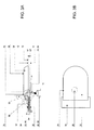
- Fig. 1 and 2 show a setup of the inventive system in a view on a display window 10 and parallel to the display window 10, respectively.
- the system comprises a recording unit 18 with here two cameras 20, 20'.
- the cameras are located behind the display window 10.
- "Behind the display window” denotes the space that is separated from a user 60 by the display window.
- "In front of the display window” is the space that is accessible by the user 60.
- the cameras 20, 20' are arranged at a distance from one another and have overlapping fields of view 24, 24'.
- the beam paths are shaped such that the fields of view 24, 24' encompass a part of a front surface 12 of the display window 10.
- optical axes 25, 25' are generally perpendicular to the display window 10. They are then deflected such that they run generally parallel to the display window 10.
- the optical axes 25, 25' are arranged at an angle ⁇ of about 90° with respect to one another. Other angles are possible, as long as the fields of view 224, 24' do not coincide.
- a display 16 is located behind the display window 10 in the immediate vicinity of a rear surface 14 thereof, preferably mounted directly to the display window 10 (mount not shown). It is located such that it lies within the field of view 24, 24' of both cameras 20, 20', as seen through the display window 10.
- the area of the front surface 12 where the display 16 is visible and that is contained in the fields of view 24, 24' of both cameras 20, 20' can act as touch surface 17.
- the touch surface 17 is represented as a narrow strip in the images taken by the cameras 20, 20'.
- the touch surface 17 may be encircled by a frame 26. This prevents distortion of the images taken by objects passing by the display window 10.
- a computer unit 40 is arranged behind the display window 10. It receives data from the recording unit 18 and is able to extract therefrom an information on whether a pointer is present, where it is located and/or how it is moved. This information is used to move a pointer object on the display 16 and/or to trigger a predetermined action, e.g. after detecting a movement corresponding to a "click” or "double click".
- the computer unit 40 may be part of a standard computer used in connection with the display 16, e.g. by running a certain program thereon.
- the inventive system preferably does not occupy more than 15% of the overall computing capacity of the computer. It is discussed below how the performance is optimized.
- the computer unit 40 is able to detect the position x'/y' of the pointer object 30 on the touch surface 17 and to transform these world coordinates x'/y' into screen coordinates x/y.
- transformation into screen coordinates x/y is particularly easy, because analysis of images taken by the left-hand side camera 20 yields coordinate y' measured with respect to the optical axis 25, and analysis of images taken by the right-hand side camera 20' yields coordinate x' measured with respect to the optical axis 25'. This will be described in more detail in connection with Figs. 5A-C.
- shield means that serve to reduce the contribution of beam paths not deflected by the deflection unit 28, 28' to the image acquired by the recording unit 18.
- They comprise a shading element 32, 32' arranged at or in the vicinity of the deflection unit 28, 28' and shown in more detail in Fig. 3A.
- They further comprise protective screens 34, 34', 35, 35' arranged at the front and/or rear surface 12, 14 of the display window 10 in the vicinity of the cameras 20, 20' and having an opening 36, 37 in the immediate vicinity of an objective 22 of the cameras 20, 20'.
- the function of these shield means will be described in connection with Fig. 3A+B.
- Fig. 3A+B show one example of a deflection unit 28 comprising a deflection surface 29, e.g. a mirror, arranged at an angle of about 45° with respect to the optical axis of the camera 20 and to the front/rear surface 12, 14.
- Beam paths 50 running in a plane parallel to the front/rear surface 12, 14 comprising the optical axis 25 are thus deflected onto the objective 22 of the camera.
- the angle of incidence ⁇ with respect to a normal to the front/rear surface 12, 14 is small, e.g. smaller than 30°.
- a further beam path 53 corresponds to direct incidence of light without deflection at the deflection surface 29, e.g. incidence of sun light or automobile headlights with a generally quite high intensity. Without shield means beam path 53 would reach the objective 22 and cause the camera control to adjust to the higher intensity, thus darkening the overall image corresponding to a smaller aperture.
- Beam path 53 is blocked by shading element 32 which is here formed in one piece with the deflection means 28.
- Shading element 32 comprises a planar face 32' running parallel to the front/rear surface 12, 14.
- the deflection surface 29 is arranged between the face 32' and the front/rear surface 12, 14.
- the planar face 32' is preferably shaped and arranged such that directly incident beam paths 53 having an angle of incidence ⁇ within a predetermined range, e.g. of 0 to 60° or 0 to 78-80°, are blocked.
- the face 32' may be rectangular and run parallel to an edge of the deflection surface 29.
- the complete body 38 of the deflection unit 28 may serve as shading element 32 blocking all beam paths having an angle of incidence ⁇ in a predetermined range.
- this angular range is chosen such that the complete field of view of the camera - if deflections at the deflection surface 29 are not taken into account - is covered. This is indicated by further beam path 53'.
- all beam paths corresponding to direct incidence of light having an angle of incidence ⁇ in a predetermined range are blocked by a shading element arranged at a distance from the front surface, potentially in combination with a protective screen on one of the surfaces 12, 14.
- Another beam path 52 having an angle of incidence ⁇ outside the range blocked by the shading element 32 is attenuated by protective screen 34 arranged on the front surface 14.
- the protective screen 34 comprises a semi-transparent foil that does not completely block but attenuate the light.
- Directly incident beam paths 52 with angles of incidence ⁇ within a further predetermined range, e.g. 45 to 80°, are affected by the protective screen 34.
- protective screen 34 attenuates beam paths 54 traveling inside the display window 10, e.g. by reflections between two panes 10', 10" of a double glazed window. Beam path 54 as shown here does thus reach the deflection surface 29 and the objective 22 with reduced intensity and has thus less potential of distorting the image.
- a further beam path 55 that is reflected at the inside of outer pane 10' is attenuated by a further protective screen 35 arranged at the rear surface 14.
- all beam paths corresponding to light reflected at one of the faces of the display window is attenuated by a protective screen arranged at the front and/or rear surface or at a distance therefrom.
- the size of the protective screens 34, 35, 34', 35' is determined from the aperture of the cameras and the thickness of the display window or the distance between two window panes 10', 10", such that no light reflected within the display window itself can reach the cameras 20, 20'. Furthermore, it is avoided that directly incident light beams reach the cameras.
- the protective screens 34, 35 By the combination of the protective screens 34, 35 with the shading element 32 it is achieved that the image acquired by the camera 20 is less distorted by reflections within the display window 10 and direct incidence of light. The contrast within the actual region of interest, i.e. the space in front of the touch surface 17, is thus enhanced.
- the protective screens 34, 35 may as well be arranged projecting laterally beyond the body of the deflection unit 28 at all sides.
- the body 38 of the deflection unite 28 is rounded in order to give as little area to serve as a grip or to step on as possible. Furthermore, the shading element 32 is tapered such that it cannot be easily gripped.
- Fig. 4 shows a flow chart of different steps of a method of processing acquired image data.
- Fig. 5A-C illustrate this method in more detail.
- image or frame 42 is taken by the recording unit 18, here a digital camera, and transmitted to the computer unit 40.
- the subset corresponds to a region of interest 44 that contains the touch surface 17 in a projection from a small angle of view.
- the discarded pixels correspond to an image of the face 32', the screens 34, 35 and/or parts of the environment.
- the touch surface 17 basically appears as a narrow strip 17' in the image 42 (see Fig. 5B).
- the z1-, z2-values can be determined during the installation of the system.
- the image 42 usually taken in color is converted into gray scale (R+G+B/3) in order to enhance contrast, especially in twilight or at night.
- Step 106 comprises a realtime motion detection and is further illustrated in Fig. 6.
- a motion detection algorithm detects where motions are present and calculates their position x', y' with respect to the optical axes 25, 25'. From these world coordinates x', y' a transformation into screen coordinates x, y is made.
- the software analyses 14 images per second for example.
- An object is identified as pointer object 30 if the value of a pixel changes by a predetermined amount within a predetermined time interval.
- an average value for each pixel is determined, e.g. by taking the average of the past 10-20 images, and the difference with respect to this average is determined (step 108).
- This average background is constantly updated. Consequently, small but continuous changes in external lightning conditions enter into the average background and will not be recognized as pointer object.
- sudden but then constant alteration of the image acquired e.g. by a chewing gum onto the touch surface, will only temporarily be identified as pointer object, but not affect the recognition of the true pointer object after a certain time.
- step 106 comprises summing up the intensity differences to the average background for all pixels within the region of interest 44 having the same x'.
- the maximum of this curve ⁇ (x') yields the coordinate x'.
- Step 110 comprises a transformation of the world coordinates x'/y' into screen coordinates x/y.
- the input parameters are x', y' (y' is derived in the same way as x') and several constant parameters gained during calibration of the system, like the position and orientation of the two cameras with respect to one another.
- aberrations within the optical system are corrected by the computer unit within step 110.
- step 112 the screen coordinates x/y then enter into the control of the display, here by a mousepointer simulator.
- the mousepointer simulator calculates off-screen coordinates and causes a mouse event if the coordinates are within the touch surface or within the screen. Additionally, mouse-up, mouse-down and mouse-click events are simulated. Any standard software can be handled with the inventive system without needing to adapt it.
- the computer unit - a specific driver of the system - has to receive information on the size of the display and on the aperture of the cameras.
- a calibration step a set of spaced apart points appears on the display, e.g. in the right and left upper corner and in the middle of the lower part of the display. The user has to touch each of this points as visible on the touch surface in a predetermined order.
- the computer unit calculates and saves the position and the distance of the cameras. These parameters are used to convert all further pointer positions x'/y' into screen coordinates.
- Fig. 6 shows the evaluation of the individual pixels of the images generated in further detail.
- a pixel lies within subset 44, i.e. has a z-coordinate between z1 and z2. If yes, the value of the pixel is converted in gray scale (It(x)). Then the median Mt(x)-1 for the pixel is calculated. This corresponds to the averaged value of the pixel in a predetermined number of past images, e.g. 14 images. The difference T(x) between the median and the actual value is evaluated. If it lies within a predetermined range (within the color scale), the variance is calculated. Otherwise, this step is skipped and the variance not updated.
Landscapes
- Engineering & Computer Science (AREA)
- General Engineering & Computer Science (AREA)
- Theoretical Computer Science (AREA)
- Human Computer Interaction (AREA)
- Physics & Mathematics (AREA)
- General Physics & Mathematics (AREA)
- Position Input By Displaying (AREA)
- Indicating Measured Values (AREA)
Applications Claiming Priority (1)
| Application Number | Priority Date | Filing Date | Title |
|---|---|---|---|
| DE102006006343 | 2006-02-08 |
Publications (2)
| Publication Number | Publication Date |
|---|---|
| EP1821184A2 true EP1821184A2 (de) | 2007-08-22 |
| EP1821184A3 EP1821184A3 (de) | 2007-11-14 |
Family
ID=37946249
Family Applications (1)
| Application Number | Title | Priority Date | Filing Date |
|---|---|---|---|
| EP07405035A Withdrawn EP1821184A3 (de) | 2006-02-08 | 2007-02-06 | System und Verfahren zur Interaktion mit einer Anzeige durch ein Schaufenster |
Country Status (2)
| Country | Link |
|---|---|
| US (1) | US20070182724A1 (de) |
| EP (1) | EP1821184A3 (de) |
Cited By (1)
| Publication number | Priority date | Publication date | Assignee | Title |
|---|---|---|---|---|
| WO2009071121A3 (de) * | 2007-12-05 | 2009-08-13 | Almeva Ag | Interaktionsanordnung zur interaktion zwischen einem bildschirm und einem zeigerobjekt |
Families Citing this family (1)
| Publication number | Priority date | Publication date | Assignee | Title |
|---|---|---|---|---|
| CN104932692B (zh) * | 2015-06-24 | 2017-12-08 | 京东方科技集团股份有限公司 | 三维触摸感测方法、三维显示设备、可穿戴设备 |
Family Cites Families (11)
| Publication number | Priority date | Publication date | Assignee | Title |
|---|---|---|---|---|
| KR900004015B1 (ko) * | 1985-07-29 | 1990-06-09 | 알프스 덴기 가부시기 가이샤 | 좌표 입력 장치 |
| JP3876942B2 (ja) * | 1997-06-13 | 2007-02-07 | 株式会社ワコム | 光デジタイザ |
| JP4422851B2 (ja) * | 1999-03-17 | 2010-02-24 | キヤノン株式会社 | 座標入力装置及び方法 |
| DE10007891C2 (de) * | 2000-02-21 | 2002-11-21 | Siemens Ag | Verfahren und Anordnung zur Interaktion mit einer in einem Schaufenster sichtbaren Darstellung |
| JP2001265516A (ja) * | 2000-03-16 | 2001-09-28 | Ricoh Co Ltd | 座標入力装置 |
| US6864882B2 (en) * | 2000-05-24 | 2005-03-08 | Next Holdings Limited | Protected touch panel display system |
| EP1297488B1 (de) * | 2000-07-05 | 2006-11-15 | Smart Technologies Inc. | Kamerabasiertes beruehrungssystem |
| US6803906B1 (en) * | 2000-07-05 | 2004-10-12 | Smart Technologies, Inc. | Passive touch system and method of detecting user input |
| US6954197B2 (en) * | 2002-11-15 | 2005-10-11 | Smart Technologies Inc. | Size/scale and orientation determination of a pointer in a camera-based touch system |
| US7042444B2 (en) * | 2003-01-17 | 2006-05-09 | Eastman Kodak Company | OLED display and touch screen |
| JP2005107890A (ja) * | 2003-09-30 | 2005-04-21 | Sanyo Electric Co Ltd | El表示装置 |
-
2007
- 2007-02-06 EP EP07405035A patent/EP1821184A3/de not_active Withdrawn
- 2007-02-07 US US11/703,289 patent/US20070182724A1/en not_active Abandoned
Cited By (3)
| Publication number | Priority date | Publication date | Assignee | Title |
|---|---|---|---|---|
| WO2009071121A3 (de) * | 2007-12-05 | 2009-08-13 | Almeva Ag | Interaktionsanordnung zur interaktion zwischen einem bildschirm und einem zeigerobjekt |
| CN101971128B (zh) * | 2007-12-05 | 2013-07-17 | 阿尔梅瓦股份公司 | 屏幕与指针对象之间交互用的交互装置 |
| US9582115B2 (en) | 2007-12-05 | 2017-02-28 | Almeva Ag | Interaction arrangement for interaction between a screen and a pointer object |
Also Published As
| Publication number | Publication date |
|---|---|
| EP1821184A3 (de) | 2007-11-14 |
| US20070182724A1 (en) | 2007-08-09 |
Similar Documents
| Publication | Publication Date | Title |
|---|---|---|
| JP4083941B2 (ja) | 座標入力装置 | |
| US20090058833A1 (en) | Optical Touchscreen with Improved Illumination | |
| EP2443481B1 (de) | Systeme und verfahren zum erfassen und nachverfolgen von strahlungsblockierobjekten auf einer oberfläche | |
| US20110205189A1 (en) | Stereo Optical Sensors for Resolving Multi-Touch in a Touch Detection System | |
| US20120250936A1 (en) | Interactive input system and method | |
| US20060044282A1 (en) | User input apparatus, system, method and computer program for use with a screen having a translucent surface | |
| US20110261016A1 (en) | Optical touch screen system and method for recognizing a relative distance of objects | |
| US20110234542A1 (en) | Methods and Systems Utilizing Multiple Wavelengths for Position Detection | |
| WO2010051633A1 (en) | Interactive input system with multi-angle reflecting structure | |
| CA2751607A1 (en) | Touch pointers disambiguation by active display feedback | |
| EP3723034A1 (de) | Vorrichtung und verfahren zur bestimmung eines falschen fingers | |
| US20110128386A1 (en) | Interactive device and method for use | |
| KR100942431B1 (ko) | 촬상소자와 광원을 이용한 터치 좌표 인식 방법 및 이를이용한 터치스크린 시스템 | |
| TWI460635B (zh) | 光學觸控系統、光學裝置及其定位方法 | |
| US20070182724A1 (en) | System and method for interacting with a display through a display window | |
| JP4570145B2 (ja) | 位置検出平面外に撮像部を有する光学式位置検出装置 | |
| JP5934216B2 (ja) | 表面上の放射線遮蔽物体を検知・追跡するシステムおよび方法 | |
| JP5530809B2 (ja) | 位置検出装置、及び画像処理システム | |
| JP4546224B2 (ja) | 座標入力方法及びその装置 | |
| JP3085482U (ja) | 入力装置 | |
| CN102981681B (zh) | 光学触控系统、光学装置及其定位方法 | |
| JP4423113B2 (ja) | 座標入力装置及びその制御方法、プログラム | |
| JP3080041U (ja) | 入力装置 | |
| TWI520037B (zh) | 光學觸控系統、光學裝置及其定位方法 | |
| US20110043636A1 (en) | Method of determining an intrusion into a monitored area and a system therefore |
Legal Events
| Date | Code | Title | Description |
|---|---|---|---|
| PUAI | Public reference made under article 153(3) epc to a published international application that has entered the european phase |
Free format text: ORIGINAL CODE: 0009012 |
|
| AK | Designated contracting states |
Kind code of ref document: A2 Designated state(s): AT BE BG CH CY CZ DE DK EE ES FI FR GB GR HU IE IS IT LI LT LU LV MC NL PL PT RO SE SI SK TR |
|
| AX | Request for extension of the european patent |
Extension state: AL BA HR MK YU |
|
| PUAL | Search report despatched |
Free format text: ORIGINAL CODE: 0009013 |
|
| AK | Designated contracting states |
Kind code of ref document: A3 Designated state(s): AT BE BG CH CY CZ DE DK EE ES FI FR GB GR HU IE IS IT LI LT LU LV MC NL PL PT RO SE SI SK TR |
|
| AX | Request for extension of the european patent |
Extension state: AL BA HR MK YU |
|
| AKX | Designation fees paid | ||
| REG | Reference to a national code |
Ref country code: DE Ref legal event code: 8566 |
|
| STAA | Information on the status of an ep patent application or granted ep patent |
Free format text: STATUS: THE APPLICATION IS DEEMED TO BE WITHDRAWN |
|
| 18D | Application deemed to be withdrawn |
Effective date: 20080515 |