EP1821186B1 - Système de stockage virtuel et procédé de contrôle correspondant - Google Patents
Système de stockage virtuel et procédé de contrôle correspondant Download PDFInfo
- Publication number
- EP1821186B1 EP1821186B1 EP06253133.0A EP06253133A EP1821186B1 EP 1821186 B1 EP1821186 B1 EP 1821186B1 EP 06253133 A EP06253133 A EP 06253133A EP 1821186 B1 EP1821186 B1 EP 1821186B1
- Authority
- EP
- European Patent Office
- Prior art keywords
- storage system
- function
- command
- storage
- faulty
- Prior art date
- Legal status (The legal status is an assumption and is not a legal conclusion. Google has not performed a legal analysis and makes no representation as to the accuracy of the status listed.)
- Not-in-force
Links
Images








Classifications
-
- G—PHYSICS
- G06—COMPUTING OR CALCULATING; COUNTING
- G06F—ELECTRIC DIGITAL DATA PROCESSING
- G06F3/00—Input arrangements for transferring data to be processed into a form capable of being handled by the computer; Output arrangements for transferring data from processing unit to output unit, e.g. interface arrangements
- G06F3/06—Digital input from, or digital output to, record carriers, e.g. RAID, emulated record carriers or networked record carriers
- G06F3/0601—Interfaces specially adapted for storage systems
- G06F3/0628—Interfaces specially adapted for storage systems making use of a particular technique
- G06F3/0662—Virtualisation aspects
-
- G—PHYSICS
- G06—COMPUTING OR CALCULATING; COUNTING
- G06F—ELECTRIC DIGITAL DATA PROCESSING
- G06F3/00—Input arrangements for transferring data to be processed into a form capable of being handled by the computer; Output arrangements for transferring data from processing unit to output unit, e.g. interface arrangements
- G06F3/06—Digital input from, or digital output to, record carriers, e.g. RAID, emulated record carriers or networked record carriers
- G06F3/0601—Interfaces specially adapted for storage systems
- G06F3/0602—Interfaces specially adapted for storage systems specifically adapted to achieve a particular effect
- G06F3/0614—Improving the reliability of storage systems
-
- G—PHYSICS
- G06—COMPUTING OR CALCULATING; COUNTING
- G06F—ELECTRIC DIGITAL DATA PROCESSING
- G06F3/00—Input arrangements for transferring data to be processed into a form capable of being handled by the computer; Output arrangements for transferring data from processing unit to output unit, e.g. interface arrangements
- G06F3/06—Digital input from, or digital output to, record carriers, e.g. RAID, emulated record carriers or networked record carriers
- G06F3/0601—Interfaces specially adapted for storage systems
- G06F3/0668—Interfaces specially adapted for storage systems adopting a particular infrastructure
- G06F3/0671—In-line storage system
- G06F3/0683—Plurality of storage devices
Definitions
- the present invention relates to a virtual storage system and control method thereof for virtualizing a plurality of storage systems logically as a single storage resource.
- storage grids wide area wide band shared file systems
- a method of virtualizing a plurality of storage systems logically as a single virtual storage resource is well-known as a storage grid operation method.
- the abstract of EP1357465 discloses a storage system 100 configured to provide a storage area to a host 300 coupled to the storage system includes a first storage device 100, 550 of a first type being configured to store data and provide one or more data-storage-related functions.
- a second storage device 100, 550 of a second type is configured to store data and provide one or more data-storage-related functions.
- a virtual volume 500, 600 provides a storage location and being associated with at least one of the first and second storage devices.
- a database 210 includes information relating to the one or more data-storage-related functions that the first and second storage devices are configured to perform.;
- a first server 200 is coupled to the first and second storage devices and has access to the database, the first server being configured to access the database in response to a data-storage-related-function request from the host involving at least one of the first and second storage devices.
- the database is accessed to determine whether or not the at least one of the first and second storage devices is capable of performing the request from the host.
- the first server is further configured to perform the request if the determination is negative or provide an instruction to the at least one of the first and second storage devices to perform the request if the determination is positive.
- EP 1517230 discloses a first storage control device with a virtual LU for showing a logical volume possessed by a second storage control device as if it were its own volume.
- data processing requested from a host device is, for example, a specific processing of large load (such as direct backup, logical volume copy, and so on), whether or not the requested processing can be executed by the second storage control device is judged.
- a command is transmitted to the second storage control device to make it take over the processing.
- a storage system having function B of a plurality of storage systems logically constituting a single storage resource receives a processing request for function B from a host computer, this storage system is capable of recognizing the process request for function B and carrying out processing.
- the respective storage systems that are virtualized logically as a single storage resource by the storage grid are not limited to having to share functions.
- the host computer recognizes the plurality of storage systems as a single storage resource. There are therefore cases where process requests for function A are sent to storage systems that do not have function A. In such cases, a command error is sent back to the host computer, and process requests for the function A are not processed appropriately.
- the present invention therefore seeks to address the problem of processing commands from a host computer in an appropriate manner even in cases where the functions in the possession of each storage system are different in a virtual storage system virtualizing a plurality of storage systems as a single storage resource.
- a virtual storage system of the present invention is as set forth in claim 1.
- FIG. 1 shows a system configuration of a virtual storage system 100 of an embodiment.
- the virtual storage system 100 is equipped with a plurality of storage systems 20A, 20B, 20C, and an external storage system 70.
- One or more host computers 51 are connected to the storage systems 20A, 20B, 20C, respectively.
- a host computer 51 having a virtualization program 63 is connected to the storage systems 20A, 20B, 20C via a SAN (Storage Area Network) 41 and recognizes the plurality of storage systems 20A, 20B, 20C logically as a single storage resource (hereinafter referred to as virtual storage system 100) due to the function of the virtualization program 63.
- SAN Storage Area Network
- Another host computer 51 that does not have a virtualization program 63 is connected to the storage systems 20A, 20B, 20C via SAN 42, a virtualization device 52, and SAN 41 and recognizes the plurality of storage systems 20A, 20B, 20C as a single virtual storage system 100 using a function of the virtualization program 63 within the virtualization device 52.
- the host computer 51 recognizes storage regions provided by the plurality of storage systems 20A, 20B, 20C logically as a single virtual storage system 100 and is capable of accessing the virtual storage system 100.
- the virtualization device 52 virtualizes the storage regions provided respectively by the plurality of storage systems 20A, 20B, 20C logically into a single storage region.
- the virtualization device 52 may be, for example, a virtualization switch, an intelligent switch, or a virtualization-dedicated device, etc.
- a system configured so as to include the virtual storage system 100 and the virtualization device 52 is referred to as a storage network system.
- the host computer 51 is comprised of an application program 60 and alternate path software 61.
- the application program 60 is, for example, a service program such as, for example, database management software, Web application software, streaming application software, and E-business application software, etc.
- the alternate path software 61 manages logical paths between the host computer 51 and logical devices within the virtual storage system 100 and executes multipath control.
- Multipath control refers to controlling of which logical path of a plurality of logical paths is used to access a logical device.
- the alternate path software 61 is comprised of a multipath management program (not shown), an inter-casing multipath program (not shown), a priority control program (not shown), and a same device correspondence table 62.
- the multipath management program carries out management and control of the whole of the alternate path software 61.
- the inter-casing multipath program recognizes a plurality of logical paths connected to a logical device 701 within an external storage system 70 via a plurality of storage systems 20 as a multipath.
- the priority control program selects logical paths to be given priority for use from a plurality of logical paths based on the respective usage rates of a plurality of logical paths connected to the same logical device.
- the same device correspondence table 62 shows the corresponding relationship between logical paths and logical devices in a network environment where different logical paths are connected to the same logical device.
- alternate path software 61 it is not essential for the alternate path software 61 to be stored within the host computer 51 and this may also be stored within the virtualization device 52.
- storage system 20 when there is no particular need for discrimination.
- the storage system 20 is comprised of a CPU (Central Processing Unit) 21, memory 22, a disc interface control section 23, a disc unit 24, FC (Fiber Channel) interface control sections 25, 26, and LAN (Local Area Network) interface control sections 27, 28.
- CPU Central Processing Unit
- memory a memory 22
- disc interface control section 23 a disc unit 24
- FC Fiber Channel interface control sections
- LAN Local Area Network
- the CPU 21 executes each of the various control processes occurring at the storage system 20 by executing each of the various programs and modules stored in the memory 22.
- the memory 22 is referred to as an internal storage device, and is comprised of non-volatile memory for storing each of the various modules etc., and volatile memory for temporarily holding computation processing results of the CPU 21.
- the CPU 21 is connected to the disc unit 24 via the disc interface control section 23.
- the disc interface control section 23 converts logical addresses outputted by the CPU 21 to LBA (Logical Block Addresses) and is capable of accessing a logical device using the CPU 21.
- LBA Logical Block Addresses
- the disc unit 24 has a plurality of disc drives 240 constituting a RAID (Redundant Arrays of Independent Inexpensive Disks).
- the disc drives 240 are physical devices such as an FC ( Fibre Channel ) disc drive, a SATA ( Serial Advanced Technology Attachment ) disc drive, a PATA ( Parallel Advanced Technology Attachment ) disc drive, a FATA(Fibre Attached Technology Adapted ) disc drive, an SAS( Serial Attached SCSI) disc drive, or an SCSI( Small Computer System Interface )disc drive, etc.
- a physical device is a real device having a real storage region.
- a logical device 242 is a virtual storage device that does not have a real storage region, with a real storage region storing the data existing in the logical device 701 within the external storage system 70.
- the storage system 20 incorporates the logical device 701 of the external storage system 70 as its own internal device and supplies this as a logical unit to the host computer 51.
- the host computer 51 is a UNIX (registered trade mark) family system
- the logical unit correlates to a device file (Device File).
- the host computer 51 is a Windows (registered trade mark) family system
- the logical unit correlates to a drive letter (Drive Name).
- a LUN Logical Unit Number
- the details of the method for virtualizing the logical device 701 of the external storage system 70 so as to be handled as an internal device of the storage system 20 are disclosed in Japanese Patent Laid-open Publication No. 2005-107645 .
- the command device 243 is a dedicated logical unit for handing over commands and statuses between the host computer 51 and the storage system 20. Commands sent from the host computer 51 to the storage system 20 are written to the command device 243. The storage system 20 executes processes corresponding to commands written to the command device 243 and writes the results of execution to the command device 243 as statuses. The details of the command management using the command device 243 are described in the following.
- the disc interface control section 23 is capable of controlling the plurality of disc drives 240 using RAID levels (for example, 0, 1, 5) defined by the RAID system.
- the RAID system manages a plurality of disc drives 240 as a single RAID group.
- a RAID group is configured from, for example, four disc drives 240 grouped together into one set (3D + 1 P), or eight disc drives 240 grouped together into one set (7D + 1P).Namely, the storage regions respectively provided by the plurality of disc drives 240 are gathered together to make up a single RAID group.
- a plurality of logical devices 241 constituting access units from the host computer 51 are defined on a RAID group. One or more logical devices 241 are then mapped on a logical unit constituted by a logical storage region recognized by the host computer 51.
- the host computer 51 is capable of accessing the logical device 241 by designating LUN and LBA.
- the FC interface control section 25 controls transfer of commands and data via SAN 43 between the storage system 20 and the external storage system 70.
- the FC interface control section 26 controls transfer of commands and data via SAN 41 between the storage system 20 and the host computer 51.
- the data communication for via the SAN 41 and 43 is a fiber channel protocol or iSCSI protocol, etc.
- SAN 43 is not essential, and the FC interface control section 25 and external storage system 70 may also be directly connected by optical fiber cable etc.
- the LAN interface control section 27 is connected to a management server 50 via a management network 40.
- the management network 40 is a LAN configured from Ethernet cable, etc.
- the data communication protocol for the management network 40 is TCP/IP.
- the management server 50 manages the production of logical units within the virtual storage system 100, the allocation of logical units to the host computer 51, and the setting (LUN masking, zoning, etc.) of access paths between the host computer 51 and the virtual storage system 100.
- the external storage system 70 has one or more disc drives 700 in a RAID configuration.
- the disc drive 700 is a storage device such as an FC ( Fibre Channel ) disc drive, a SATA ( Serial Advanced Technology Attachment ) disc drive, a PATA ( Parallel Advanced Technology Attachment ) disc drive, a FATA ( Fibre Attached Technology Adapted ) disc drive, an SAS ( Serial Attached SCSI ) disc drive, or an SCSI( Small Computer System Interface )disc drive, etc.
- a logical device 701 is formed on the plurality of disc drives 700.
- the external storage system 70 may be a different type of storage system as the storage system 20 or may be the same type of storage system.
- the storage system 20 determines whether this access request is an access request to logical device 241 taken as its own internal device or an access request to logical device 701 taken as an external device. If this is an access request to the logical device 701, address conversion is carried out for between the logical device 242 and the logical device 701 and an access request to the logical device 701 is sent to the external storage system 70.
- the service processor 81 is a computer terminal for setting configuration information (including a device information table 106 and configuration information 108 described later) of the storage system 20 and acquiring operation information etc.
- the service processor 81 is connected to the LAN interface control section 28 within the storage system 20.
- Each service processor 81 connected to each storage system 20 is connected to one master service processor 82.
- the master service processor 82 uniformly manages information (configuration information, operation information etc. for the storage system 20) collected from each of the service processors 81.
- One of the plurality of service processors 81 may function as the master service processor, or each storage system 20 may be directly connected to the master service processor 82.
- the virtual storage system 100 exhibits a range where transfer of commands and execution of volume migration between each of the storage systems 20 is possible by transmitting and receiving configuration information between each of the storage systems 20.
- the range of the virtual storage system 100 includes the plurality of storage systems 20 and the external storage system 70.
- the range of the virtual storage system 100 includes the plurality of storage systems 20 but does not include the external storage system 70.
- Each storage system 20 is capable of being configured as a disc array system provided with a plurality of disc drives 240 in, for example, a RAID configuration, or is capable of being configured as a virtual switch where each storage system 20 itself constitutes a SCSI target.
- a storage system 20 may also be referred to as a storage control device.
- the management network 40 is connected to one or more host computers 51. Further, one or more client computers 30 are connected to the management network 40. Each client computer 51 is connected to a host computer 51 via the management network 40 and is capable of requesting input and output of data to the virtual storage system 100 via the application program 60.
- FIG. 2 shows a same device correspondence table 62.
- the same device correspondence table 62 stores a "path number”, “storage system identifier”, “LUN”, and “device identifier” in a correlating manner.
- Pulth number indicates the number of a logical path.
- Storage system identifier indicates information for uniquely identifying a storage system 20 or external storage system 70 within the virtual storage system 100.
- LUN indicates a logical unit number for within the storage system 20 or the external storage system 70.
- Device identifier indicates information for uniquely identifying logical devices 241, 242, 701 within the virtual storage system 100.
- LUN is different every storage system 20 even for the same logical device because a host storage domain is adopted.
- the same device correspondence table 62 holds a virtualization layer (in the example shown in FIG. 1 , host computer 51 or virtualization device 52) virtualizing the plurality of storage systems 20 into a single virtual storage system 100.
- a virtualization layer in the example shown in FIG. 1 , host computer 51 or virtualization device 52
- FIG. 3 shows the various programs and tables stored in the memory 22.
- An operating system 101, function registration program 102, function - device correspondence recognition program 103, command - function correspondence table 104, function - device correspondence table 105, device information table 106, fault information 107, and configuration information 108 are stored in the memory 22.
- the command - function correspondence table 104 holds a correspondence relationship between commands issued by the host computer 51 and functions corresponding to these commands. For example, snapshots, replications, and remote copies exist as specific examples of "functions" requested by the host computer 51 to the virtual storage system 100.
- the function registration program 102 registers command and function correspondence information in a command - function correspondence table 104.
- the function - device correspondence table 105 holds a correspondence relationship for functions required by the host computer 51 and storage systems 20 in possession of these functions.
- the function - device correspondence recognition program 103 registers a correspondence relationship between the storage systems 20 and the functions in the function - device correspondence table 105.
- the device information table 106 holds attributes of logical devices.
- the fault information 107 holds fault information for each storage system 20.
- the configuration information 108 is mapping information indicating a corresponding relationship between the physical device 701 within the external storage system 70 and the logical devices 242 within each storage system 20.
- mapping information indicating a corresponding relationship between the physical device 701 within the external storage system 70 and the logical devices 242 within each storage system 20.
- the details of mapping information for mapping the external device at the internal devices is disclosed in Japanese Patent Laid-open Publication No. 2005-107645 .
- command management described in the following, it is by no means essential for the virtual storage system 100 to hold a corresponding relationship for the commands, functions, and storage systems 20 in the table format described above providing that which function a command issued by the host computer 51 corresponds to and which storage system 20 has this function can be retrieved, and it is possible for this command to be transferred to the retrieved storage system 20.
- the corresponding relationship for the commands, functions and storage system 20 can be held as a list structure or other format.
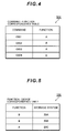
- FIG. 4 shows the command - function correspondence table 104.
- the command - function correspondence table 104 holds a correspondence relationship between commands issued from the host computer 51 to the virtual storage system 100 and functions corresponding to these commands.
- command C001 is a command for calling function A at the virtual storage system 100.
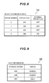
- FIG. 5 shows a function - device correspondence table 105.
- the function - device correspondence table 105 holds a correspondence relationship for functions required by the host computer 51 and storage systems 20 in possession of these functions.
- storage system 20A has function B.
- FIG. 8 shows the device information table 106.
- the device information table 106 is for holding attributes of logical devices and is stored in the memory 22 within the storage system 20.
- the device information table 106 stores a "device number”, "status flag”, and "external device flag” in a correlating manner.
- Device number is information for uniquely identifying logical devices 241, 242 within a storage system 20.
- “Status flag” indicates whether the logical devices 241, 242 within the storage system 20 are used or not used (empty). "ON” in the drawing indicates that the logical devices 241 and 242 are being used.
- “External device flag” indicates whether or not the logical device 242 within the storage system 20 is being used as an external device (logical device 701).
- "ON” in the drawing indicates that the logical device 242 is being used as an external device.
- "OFF” in the drawing indicates that the logical device 241 is being used as an internal device.
- the default value of the external device flag is “OFF”, and "OFF" is changed to "ON” when the logical device 242 within the storage system 20 is mapped to the logical device 701 within the external storage system 70.
- FIG. 9 shows fault information 107.
- Fault information 107 is information indicating whether or not each storage system 20 is functioning normally or has a fault.
- Fault information 107 is information indicating whether or not each storage system 20 is functioning normally or has a fault.
- an example is shown where it is determined that a fault is occurring at a storage system 20 in the event that the storage system is in a state where commands from the host computer 51 cannot be received, but it is also possible to determine whether or not a fault is occurring at a storage system 20 based on a preset fault level.
- the fault level used in fault determination may be inputted by the user, or may be a fault level selected by a user from a plurality of fault levels designated by a user.
- Each memory 22 of each storage system 20 and the management server 50 hold the fault information 107.
- Typical command processes executed by the storage system 20 are described with reference to FIG. 10 .
- the storage system 20 determines whether or not the logical device receiving the access request is an external device (logical device 701) by referring to device information table 106 (S102).
- the storage system 20 accesses the internal device using normal operations (S103).
- the storage device 20 sends a command for accessing the external device to the external storage system 70 (S104).
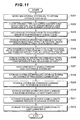
- FIG. 11 a description is given with reference to FIG. 11 of command management executed by the virtual storage system 100.
- a storage system 20 having this function is searched for and the command is transferred to the retrieved storage system 20.
- a process to add storage system 20C to the virtual storage system 100 is then carried out (S201). Namely, a process to connect the storage system 20C to the SAN 41 and recognize the host computer 51 and the virtualization device 52 (for example, recognition of a storage system identifier of the storage system 20C, recognition of the LUN of a logical unit within the storage system 20C, and recognition of a path number of a logical path connecting to this logical unit, etc.) is carried out. In the event that the storage system 20C shares the logical device 701 of the external storage system 70, the storage system 20 may be connected to SAN 43.
- the management server 50 recognizes that a storage system 20C is newly added to the virtual storage system 100, recognizes that the storage system 20C has a program P3, additionally registers a function A to the command - function correspondence table 104 managed by itself, and additionally registers storage system 20C to the function - device correspondence table 105 managed by itself (S202).
- Information to the effect that the storage system 20C has a program P3 corresponding to function A may be acquired as a result of input by a user to the management server 50, or may be acquired from a program during installation of this program (program sending commands to program P3) corresponding to program P3 to the host computer 51.
- the management server 50 notifies the respective storage systems 20A, 20B that a program P3 possessed by the storage system 20C has been newly added to the virtual storage system 100 (S203).
- the storage systems 20A, 20B may be notified by the management server 50 individually, the management server 50 may notify a specific storage system 20, or a specific storage system 20 may notify another storage system 20.
- the respective storage systems 20A, 20B additionally register the storage system 20C and the function A to the function - device correspondence tables 105 held within their own memories 22 in a correlating manner, and additionally register commands C001, C002, C003 and function A in the command - function correspondence table 104 in a correlating manner (S204).
- the management server 50 notifies the storage system 20C of a corresponding relationship of existing functions (programs) within the virtual storage system 100, commands corresponding to these functions, and storage systems 20 having these functions (S205).
- the storage system 20C additionally registers storage systems 20A, 20B and function B in a correlated manner to the function - device correspondence table 105 held within its own memory 22 and additionally registers command C004 and function B in a correlating manner to command - function correspondence table 104 based on information (the correspondence relationship of existing programs (functions) within the virtual storage system 100 and storage systems 20 having these programs), notification of which was given by the management server 50 (S206).
- the host computer 51 sends command C001 corresponding to program P3 to the virtual storage system 100 (S207).
- the host computer 51 does not transmit the command C001 while individually recognizing the individual storage systems 20A, 20B, 20C. Which of the storage systems 20A, 20B and 20C receives the command is therefore decided on a case by case basis.
- the description is continued assuming the case that the storage system 20A receives the command C001.
- the storage system 20A retrieves which program the command C001 corresponds to and which storage system 20 is in possession of this program by referring to the command - function correspondence table 104 and the function - device correspondence table 105 held within its own memory 22 (S208).
- the storage system 20C implements the steps S210 and S212 described in the following.
- the storage system 20A transfers command C001 to the storage system 20C via SAN 43 (S209).
- the storage system 20A sends the real data to the storage system 20C. Transmission of the real data may take place collectively a single time or may be carried out partially split across a plurality of times.
- the command C001 intends to process exists in the logical device 701 of the external storage system 70
- supervision of control of the logical device 701 is changed from the storage system 20A to the storage system 20C.
- the storage system 20A may also hold information correlating the command and the storage system 20 of the transfer destination as command transfer history information and then transfer a command to another storage system 20 by referring to this history information when a new command is received from the host computer 50.
- the storage system 20A notifies the host computer 51 of normal receipt of a command (S210).
- the storage system 20C notifies the storage system 20A of completion at the stage where processing of command C001 is complete (S211).
- the storage system 20A receiving notification of completion from the storage system 20C then notifies the host computer 51 that the processing of command C001 is complete (S212).
- step S201 As a further method of command management shown in FIG. 11 , a method exists where, for example, execution of the steps takes place in the order of step S201, S202, S205, S206, the storage system 20C notifies the storage systems 20A, 20B that program P3 and storage system 20C have been newly added, step S204 is then implemented, and execution of S207 to S212 then takes place in order.
- FIG. 12 a description is given with reference to FIG. 12 of further command management executed by the virtual storage system 100.
- the management server 50 is interrogated as to which storage system 20 has this function.
- the management server 50 receiving this interrogation retrieves the storage system 20 having the function corresponding to this command and notifies the storage system 20 that is the destination of this interrogation.
- the storage system 20 receiving notification from the management server 50 then transfers the command to the storage system 20 having the function corresponding to this command.
- a process to add storage system 20C to the virtual storage system 100 is then carried out (S301). Namely, a process to connect the storage system 20C to the SAN 41 and recognize the host computer 51 and the virtualization device 52 (for example, recognition of a storage system identifier of the storage system 20C, recognition of the LUN of a logical unit within the storage system 20C, and recognition of a path number of a logical path connecting to this logical unit, etc.) is carried out. In the event that the storage system 20C shares the logical device 701 of the external storage system 70, the storage system 20 may be connected to SAN 43.
- the management server 50 recognizes that a storage system 20C is newly added to the virtual storage system 100, recognizes that the storage system 20C has a program P3, additionally registers a function A to the command - function correspondence table 104 managed by itself, and additionally registers storage system 20C to the function - device correspondence table 105 managed by itself (S302).
- the host computer 51 sends command C001 corresponding to program P3 to the virtual storage system 100 (S303).
- the host computer 51 does not transmit the command C001 while individually recognizing the individual storage systems 20A, 20B, 20C. Which of the storage systems 20A, 20B and 20C receives the command is therefore decided on a case by case basis.
- the description is continued assuming the case that the storage system 20A receives the command C001.
- the storage system 20A determines whether or not it is itself in possession of function A capable of executing command C001. In this embodiment, the storage system 20A is not in possession of function A capable of executing command C001 and therefore interrogates the management server 50 as to which storage system 20 is in possession of the function A capable of executing command C001 (S304).
- the management server 50 receiving the interrogation then refers to the command - function correspondence table 104 and the function - device correspondence table 105 it manages itself and retrieves the storage system 20C having the function A capable of executing the command C001 (S305).
- the management server 50 notifies the storage system 20A that the storage system 20 in possession of the function A capable of executing the command C001 is the storage system 20C (S306).
- the storage system 20A transfers command C001 to the storage system 20C (S307).
- the storage system 20A sends the real data to the storage system 20C. Transmission of the real data may take place collectively a single time or may be carried out partially split across a plurality of times.
- the command C001 intends to process exists in the logical device 701 of the external storage system 70
- supervision of control of the logical device 701 is changed from the storage system 20A to the storage system 20C.
- the storage system 20A notifies the host computer 51 of normal receipt of a command (S308).
- the storage system 20C notifies the storage system 20A of completion at the stage where processing of command C001 is complete (S309).
- the storage system 20A receiving notification of completion from the storage system 20C then notifies the host computer 51 that the processing of command C001 is complete (S310).
- the network configuration of FIG. 1 is such that the networks (SAN 41, 42) for issuing commands from the host computer 51 to each storage system 20 and the network (management network 40) for the management server 50 to transmit and receive management information between each storage system 20 are different outbound methods but this embodiment may also be applied to inbound methods. For example, this becomes an inbound method if a configuration is adopted where the management server 50 transmits and receives management information to and from each storage system 20 via the SAN 41.
- the host computer 51 holds the alternate path software 61, the command - function correspondence table 104, and the function - device correspondence table 105, and is aware of the storage system 20 in possession of the function corresponding to the command and of the logical path connecting from the host computer 51 to the logical device under the management of the storage system 20.
- the host computer 51 While a command is issued, the host computer 51 refers to the command - function correspondence table 104 and the function - device correspondence table 105 so as to retrieve which storage system 20 is in possession of the function corresponding to this command (S401).
- the host computer 51 selects a logical device to connect to the host computer 51 from the logical devices under the control of the retrieved storage system 20 and issues the command (S402). In this way, the host computer 51 can directly issue a command to the storage system 20 in possession of the function corresponding to the command.
- the host computer 51 may also issue a command by establishing a logical path in advance to all the logical devices under the control of the storage system 20 and selecting a logical path connecting to a logical device under the control of the storage system 20 in possession of the function corresponding to the command using the alternate path software 61.
- the virtualization device 52 holds the alternate path software 61, the command - function correspondence table 104, and the function - device correspondence table 105, and is aware of the storage system 20 in possession of the function corresponding to the command and of the logical path connecting from the virtualization device 52 to the logical device under the management of the storage system 20.
- the virtualization device 52 When a command is received from the host computer 51, the virtualization device 52 refers to the command - function correspondence table 104 and the function - device correspondence table 105 so as to retrieve which storage system 20 is in possession of the function corresponding to this command (S501).
- the virtualization device 52 selects a logical device connected to the virtualization device 52 via the logical path from the logical devices under the control of the retrieved storage system 20 and transfers a command (S502). In this way, the virtualization device 52 can transfer a command to the storage system 20 in possession of the function corresponding to the command.
- the virtualization device 52 may also transfer a command by establishing a logical path in advance to all the logical devices under the control of the storage system 20 and selecting a logical path connecting to a logical device under the control of the storage system 20 in possession of the function corresponding to the command using the alternate path software 61.
- the command process shown in FIG. 14 may also be executed at a virtualization layer virtualizing a plurality of storage systems 20 into a single virtual storage system 100.
- FIG. 15 a description is given with reference to FIG. 15 of a command process executed by the master service processor 82.
- the master service processor 82 is interrogated as to which storage system 20 has this function.
- the master service processor 82 receiving this interrogation retrieves the storage system 20 having the function corresponding to this command and notifies the storage system 20 that is the destination of this interrogation.
- the storage system 20 receiving notification from the master service processor 82 transfers the command to the storage system 20 having the function corresponding to this command.
- a process to add storage system 20C to the virtual storage system 100 is then carried out (S601). Namely, a process to connect the storage system 20C to the SAN 41 and recognize the host computer 51 and the virtualization device 52 (for example, recognition of a storage system identifier of the storage system 20C, recognition of the LUN of a logical unit within the storage system 20C, and recognition of a path number of a logical path connecting to this logical unit, etc.) is carried out. In the event that the storage system 20C shares the logical device 701 of the external storage system 70, the storage system 20 may be connected to SAN 43.
- the master service processor 82 recognizes that a storage system 20C is newly added to the virtual storage system 100, recognizes that the storage system 20C has a program P3, additionally registers a function A to the command - function correspondence table 104 managed by itself, and additionally registers storage system 20C to the function - device correspondence table 105 managed by itself (S602).
- the host computer 51 sends command C001 corresponding to program P3 to the virtual storage system 100 (S603).
- the host computer 51 does not transmit the command C001 while individually recognizing the individual storage systems 20A, 20B, 20C. Which of the storage systems 20A, 20B and 20C receives the command is therefore decided on a case-by-case basis.
- the description is continued assuming the case that the storage system 20A receives the command C001.
- the storage system 20A determines whether or not it is itself in possession of function A capable of executing command C001. In this embodiment, the storage system 20A is not in possession of function A capable of executing command C001 and therefore interrogates the master service processor 82 as to which storage system 20 is in possession of the function A capable of executing command C001 (S604).
- the master service processor 82 receiving the interrogation then refers to the command - function correspondence table 104 and the function - device correspondence table 105 it manages itself and retrieves the storage system 20C having the function A capable of executing the command C001 (S605).
- the master service processor 82 notifies the storage system 20A that the storage system 20 in possession of the function A capable of executing the command C001 is the storage system 20C (S606).
- the storage system 20A then transfers command C001 to the storage system 20C (S607).
- the storage system 20A sends the real data to the storage system 20C. Transmission of the real data may take place collectively a single time or may be carried out partially split across a plurality of times.
- the command C001 intends to process exists in the logical device 701 of the external storage system 70
- supervision of control of the logical device 701 is changed from the storage system 20A to the storage system 20C.
- the storage system 20A notifies the host computer 51 of normal receipt of a command (S608).
- the storage system 20C notifies the storage system 20A of completion at the stage where processing of command C001 is complete (S609).
- the storage system 20A receiving notification of completion from the storage system 20C then notifies the host computer 51 that the processing of command C001 is complete (S61 0).
- the master service processor 82 holds the command - function correspondence table 104 and function - device correspondence table 105, but is is also possible for the service processor 81 to hold the command - function correspondence table 104 and function - device correspondence table 105.
- the service processor 81 is connected to the respective storage systems 20, even if the service processor 81 is capable of determining whether or not it is a storage system 20 having a function corresponding to the command itself, it is not capable of determining whether or not other storage systems 20 are storage systems 20 having a function corresponding to the command.
- the master service processor 82 is capable of managing functions of all of the storage systems 20 and is therefore capable of determining which storage system 20 is a storage system 20 having a function corresponding to the command.
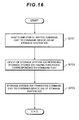
- command management used by the command device 243 a description is given with reference to FIG. 16 of command management used by the command device 243. It is taken that the command - function correspondence table 104 and function - device correspondence table 105 are stored in the memory 22 of each storage system 20 and the command device 243.
- the host computer 51 writes the command C001 to the command device 243 of the storage system 20A (S701).
- the CPU 21 of the storage system 20A refers to the command - function correspondence table 104 and function - device correspondence table 105 stored in the memory 22 and the command device 243 and retrieves the storage system 20C in possession of the function A corresponding to the command C001 (S702).
- the storage system 20A does not send the command C001 back to the host computer 51 but rather extends the command process and transfers the command C001 to the command device 243 of the storage system 20C (S703).
- the command device 243 of the storage system 20A In the event that the command received by the command device 243 of the storage system 20A is transferred to the storage system 20C, transfer takes place to the command device 243 of the storage system 20C using the method with which the command device 243 received the command. In this case, the command device 243 of the storage system 20C has a method for detecting the storage system 20A. In the event that there is no command device 243 at the storage system 20C, it is possible to transfer the command from the storage system 20A to the storage system 20C after converting the command to a format recognizable by the storage system 20C.
- FIG. 17 a description is given with reference to FIG. 17 of a process for carrying out command management as a result of the host computer 51 re-issuing a command.
- the storage system 20A retrieves a storage system 20 in possession of the function corresponding to the command ( FIG. 11 : S208).
- the storage system 20A requests re-issuance of the command to the host computer 51 and notifies the host computer 51 of which storage system 20 is in possession of the function corresponding to the command.
- the host computer 51 receiving the command reissue request then re-issues the command to the storage system in possession of the function corresponding to the command.
- the host computer 51 then issues the command C001 to the storage system 20A (S801).
- the storage system 20A refers to the command - function correspondence table 104 and function - device correspondence table 105 managed by itself and retrieves the storage system 20C in possession of the function A corresponding to the command C001 (S802).
- the storage system 20A requests re-issue of the command C001 to the host computer 51 and notifies the host computer 51 that the storage system 20 in possession of the function A corresponding to the command C001 is the storage system 20C (S803).
- the host computer 51 then receives the command re-issue request and notification that the storage system 20 in possession of the function A corresponding to the command C001 is the storage system 20C from the storage system 20A (S804).
- the host computer 51 re-issues the command C001 to the storage system 20C (S805).
- the storage system 20A sends the real data to the storage system 20C. Transmission of the real data may take place collectively a single time or may be carried out partially split across a plurality of times.
- the command C001 intends to process exists in the logical device 701 of the external storage system 70
- supervision of control of the logical device 701 is changed from the storage system 20A to the storage system 20C.
- the storage system 20A retrieves which storage system 20 is in possession of the function corresponding to the command issued by the host computer 51 but it is also possible for this to be retrieved by the management server 50 or master service processor 82, with the host computer 51 being notified of command re-issue requests and retrieval results etc.
- a command re-issue request is by no means essential to the process of FIG. 17 .
- the host computer 51 may also re-issue the command C001 to the storage system 20C at the stage of receiving notification that the storage system 20 in possession of the function A corresponding to the command C001 is the storage system 20C from the storage system 20A.
- the storage system 20C may retrieve the storage systems 20A, 20B in possession of the remote copy function, transfer the remote copy command from the storage system 20C to the storage systems 20A, 20B, and execute remote copying between the storage system 20A and the storage system 20B.
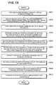
- FIG. 18 a description is given with reference to FIG. 18 of a process for when a fault occurs during transfer of a command in the method of FIG. 11 to FIG. 16 .
- a description is given of an example where a fault occurs at the storage system 20C and the host computer 51 issues the command C001 to the storage system 20A directly after notification of a fault report from the storage system 20C to the management server 50 (i.e. when the host computer 51 and the storage system 20B do not recognize the fault of the storage system 20C).
- the storage system 20C reports the fault to the management server 50 (S901).
- the host computer 51 issues the command C001 to the storage system 20A prior to recognizing the fault of the storage system 20C (S902).
- the storage system 20A refers to the command - function correspondence table 104 and function - device correspondence table 105 managed by itself and retrieves the storage system 20C in possession of the function A corresponding to the command C001 (S903).
- the storage system 20A then transfers command C001 to the storage system 20C (S904).
- the storage system 20A then recognizes the storage system 20C is faulty as a result of receiving the error report from the storage system 20C, and the "status" of the storage system 20C of the fault information 107 is updated to "faulty" (S906).
- step S907 If another storage system 20 in possession of the function A corresponding to the command C001 exists (S907: YES), the storage system 20A returns to the process of step S903.
- the storage system 20A reports the fault of the storage system 20C to the management server 51 (S909).
- the management server 51 updates the "status" of the storage system 20C of the fault information 107 managed by itself to "faulty".
- FIG. 19 a description is given with reference to FIG. 19 of another process for when a fault occurs during transfer of a command in the method of FIG. 11 to FIG. 16 .
- a description is given of an example of a case where the command C001 is issued from the host computer 51 to the storage system 20A after a fault occurs at the storage system 20C, the management server 50 is notified of a fault report by the storage system 20C, and each of the storage systems 20 are notified of the fault report by the management server 51 (i.e. when each storage system 20 recognizes the fault of the storage system 20C).
- the storage system 20C When a fault occurs at the storage system 20C, the storage system 20C reports the fault to the management server 50 (S1001).
- the management server 50 notifies all of the storage systems 20 within the virtual storage system 100 of the fault of the storage system 20C (S1002).
- Each storage system 20 then recognizes that the storage system 20C is currently faulty from the notification from the management server 50 and updates the "status" of the storage system 20C of the fault information 107 to "faulty" (S1003).
- the host computer 51 issues the command C001 to the storage system 20A prior to recognizing the fault of the storage system 20C (S1004).
- the storage system 20A refers to the command - function correspondence table 104 and function - device correspondence table 105 managed by itself, retrieves the storage system 20C in possession of the function A corresponding to the command C001, refers to the fault information 107, and recognizes that the storage system 20C is faulty (S1005).
- the storage system 20A then reports an error to the host computer 51 (S1006).
- step S1005 in the event that a plurality of storage systems 20 in possession of a function A corresponding to the command C001 exist, the storage system 20A may also transfer the command C001 to a storage system 20 operating normally.
- FIG. 20 of load distribution within the virtual storage system 100.
- an example is shown of the case where the load on the storage system 20C of the plurality of storage systems 20 within the virtual storage system 100 is large.
- the management server 50 acquires load information from each of the storage systems 20 within the virtual storage system 100 and recognizes that the load is concentrated on the storage system 20C (S1101). Resource rate of operation and occupancy rate of each storage system 20 etc. exists as load information.
- the management server 50 notifies the storage system 20C that the load is concentrated on the storage system 20C (S1102).
- the storage system 20C selects logical devices that are not using the program P3 only installed on the storage system 20C (hereinafter referred to as transfer candidate logical devices) as logical devices that are transfer candidates (S1103).
- transfer candidate logical devices logical devices that are transfer candidates
- the reason logical devices that are not using the program P3 installed only on storage system 20C are selected as transfer candidate logical devices is because there is no load dispersion in the case where the load on the program P3 installed only on storage system 20C is large even if a logical device using the program P3 is selected as a logical device that is a candidate for transfer.
- the storage system 20C notifies the management server 50 of transfer of the transfer candidate logical device (S1104).
- the management server 50 then refers to the resource rate of operation of each storage system 20 and determines a transfer destination storage system 20 for the transfer candidate logical device (S1105).
- a transfer destination storage system 20 for the transfer candidate logical device S1105.
- an example is shown of the case where storage system 20A is selected as the transfer destination storage system 20.
- the management server 50 in addition to designating the storage system 20A of the transfer destination at the storage system 20C, transmits a transfer instruction for the transfer candidate logical device (S1106).
- the storage system 20C transfers the transfer candidate logical device to the transfer destination storage system 20A under the instruction of the management server 50 (S1107).
- Which storage system 20 is made the transfer destination storage system 20 may be inputted to the storage system 20C by a system administrator via the service processor 81 or may be designated by the host computer 51 to be the storage system 20C.
- a command process taking into consideration differences in performance of the plurality of storage systems 20 constituting the virtual storage system 100 is described with reference to FIG. 21 and FIG. 22 .
- FIG. 21 shows specification information 109.
- the specification information 109 is comprised of processing power, port performance, and caching capacity, etc. of each storage system 20A, 20B, 20C.
- the specification information 109 is stored in the memory 22 of each storage system 20, the management server 50, the master service processor 82, and the service processor 81, etc.
- the storage system 20A When the command is received from the host computer 51 (S1201), the storage system 20A refers to the specification information 109 and retrieves high-performance storage systems from the virtual storage system 100 (S1202). Here, an example is shown where the storage system 20C is a high-performance storage system.
- the storage system 20A transfers the command from the host computer 51 to the storage system 20C (S1203). It is then possible to improve the overall processing performance of the virtual storage system 100 by having the high-performance storage system process a large number of commands. For example, with a usual host access, it is preferable for as much processing as possible to be carried out at the high-performance storage system 20C, with processes such as I/O processes such as copying etc. (that do not require high-performance) being carried out at the other storage system 20A.
- the high-performance storage system 20C and the other storage system 20A process I/O requests are determined using a ratio identifying the difference in performance of the high-performance storage system 20C and the other storage system 20A. For example, if the caching capacity of the high-performance storage system 20C is twice the caching capacity of the other storage system 20A, the number of I/O processes of the high-performance storage system 20C is made to be twice the number of I/O processes of the other storage system 20A.
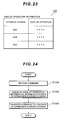
- a command process taking into consideration differences in rate of operation of the plurality of storage systems 20 constituting the virtual storage system 100 is described with reference to FIG. 23 and FIG. 24 .
- FIG. 23 shows rate of operation information 110.
- the rate of operation information 110 contains the range of operation of each storage system 20A, 20B, 20C (the processor usage rate of CPU 22, the number of I/O processes (IOPS) occurring per unit time of the CPU 22, the data transfer amount (transfer rate) per unit time of the interface control section 26, and the time (response time) between the storage system 20 receiving an I/O request from the host computer 51 and making a response, etc.).
- the rate of operation information 110 is stored in the memory 22 of each storage system 20, the management server 50, the master service processor 82, and the service processor 81, etc.
- the storage system 20A When the command is received from the host computer 51 (S1301), the storage system 20A refers to the rate of operation information 110 and retrieves a low rate of operation storage system 20 from within the virtual storage system 100 (S1302). Here, an example is shown of the case where the rate of operation of the storage system 20C is low.
- the storage system 20A transfers the command from the host computer 51 to the storage system 20C (S1303). It is then possible to improve the overall processing performance of the virtual storage system 100 by having the low rate of operation storage system 20C process a large number of commands. For example, with a usual host access, it is preferable for as much processing as possible to be carried out at the low rate of operation storage system 20C, with processes such as I/O processes such as copying etc. (that do not require a low rate of operation) being carried out at the other storage system 20A.
- the low rate of operation storage system 20C and the other storage system 20A process I/O requests are determined using a ratio identifying the difference in rate of operation of the low rate of operation storage system 20C and the other storage system 20A. For example, if the rate of operation of the storage system 20C is half of the rate of operation of the other storage system 20A, the number of I/O processes of the storage system 20C is made to be twice the number of I/O processes of the other storage system 20A.
- a main section retrieving a high-performance system or "a main section retrieving a low rate of operation storage system” is not limited to each of the storage systems 20 and may also be, for example, the management server 50, the service processor 81, the master service processor 82, the host computer 51, or the virtualization device 52.
- the processing procedure while the storage system 20A receiving the command from the host computer 51 transfers the command to the storage system 20C in the process of FIG. 11 to FIG. 20 described above may conform to a method of substituting "retrieval of a storage system having a function corresponding to a command" with "retrieval of high-performance storage system” or "retrieval of low rate of operation storage system".
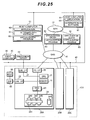
- FIG. 25 shows a system configuration of a virtual storage system 101.
- Devices etc. with the same numerals as numerals shown in FIG. 1 are the same devices etc. and detailed description thereof is therefore omitted.
- the virtual storage system 101 virtualizes the plurality of storage systems 20A, 20B, 20C into a single storage system 101.
- the point of distinction with the virtual storage system 100 shown in FIG. 1 is that the virtual storage system 101 does not have an external storage system 70. Namely, each storage system 20 has a real device for storing real data. It is also possible to carry out processes (processes shown in FIG. 11 to FIG. 22 ) such as the command management and fault processing etc. described above for the virtual storage system 101.
Landscapes
- Engineering & Computer Science (AREA)
- Theoretical Computer Science (AREA)
- Human Computer Interaction (AREA)
- Physics & Mathematics (AREA)
- General Engineering & Computer Science (AREA)
- General Physics & Mathematics (AREA)
- Information Retrieval, Db Structures And Fs Structures Therefor (AREA)
- Memory System Of A Hierarchy Structure (AREA)
Claims (10)
- Système de stockage virtuel (100) ayant une pluralité de systèmes de stockage (20) pour recevoir des instructions en provenance d'un ordinateur hôte, au moins l'un des systèmes de stockage ayant une première fonction, un serveur de gestion (50) et une couche de virtualisation pour virtualiser la pluralité de systèmes de stockage logiquement dans une ressource de stockage unique prévue dans l'ordinateur hôte (51),
caractérisé en ce que chaque système de stockage (20) comprend :une section de stockage pour stocker une instruction envoyée par l'ordinateur hôte au système de stockage virtuel,des informations de correspondance instruction - fonction (104) indicatives d'une relation de correspondance entre des instructions envoyées par l'ordinateur hôte et une ou plusieurs fonctions correspondant aux instructions, les informations de correspondance instruction - fonction (104) incluant un identifiant d'instruction et un identifiant de fonction,des informations de correspondance fonction - dispositif (105) indicatives d'une relation de correspondances entre chaque fonction requise par l'ordinateur hôte (51) et un ou plusieurs desdits systèmes de stockage, parmi la pluralité de systèmes de stockage fournissant la ressource de stockage unique, en possession d'un programme pour la fonction, les informations de correspondance fonction - dispositif (105) comprenant l'identifiant de fonction et un identifiant de système de stockage,une section de détermination pour déterminer si le système de stockage respectif, recevant l'instruction envoyée par l'ordinateur hôte, dispose ou non d'une fonction correspondant à l'instruction en se reportant aux informations de correspondance instruction - fonction et aux informations de correspondance fonction - dispositif,une section d'exécution pour exécuter l'instruction reçue si la section de détermination détermine que le système de stockage respectif dispose de la fonction correspondant à l'instruction reçue,une section de récupération pour récupérer, si la section de détermination détermine que le système de stockage respectif ne dispose pas de la fonction correspondant à l'instruction reçue, un ou plusieurs systèmes de stockage, parmi la pluralité de systèmes de stockage fournissant la ressource de stockage unique, en possession d'un programme pour la fonction capable d'exécuter l'instruction envoyée par l'ordinateur hôte en se reportant aux informations de correspondance instruction - fonction et aux informations de correspondance fonction - dispositif, etune section de transfert pour transférer l'instruction reçue vers un système de stockage récupéré d'un ou plusieurs systèmes de stockage en possession d'un programme pour la fonction capable d'exécuter l'instruction envoyée par l'ordinateur hôte,dans lequellorsque l'instruction est reçue en provenance de l'ordinateur hôte, alors le système de stockage est conçu pour notifier à l'ordinateur hôte la réception normale de l'instruction,le système de stockage récupéré est conçu pour notifier au système de stockage la fin du traitement de l'instruction transférée lorsque le traitement de l'instruction transférée est terminé, etle système de stockage est conçu pour recevoir la notification de fin en provenance du système de stockage récupéré et ensuite pour notifier à l'ordinateur hôte que le traitement de l'instruction reçue est terminé,caractérisé en ce que le serveur de gestion contient égalementdes informations de correspondance instruction - fonction (104) et des informations de correspondance fonction - dispositif (105),dans lequellorsqu'un nouveau système de stockage (20C), ayant une seconde fonction, pour recevoir des instructions en provenance de l'ordinateur hôte est ajouté à la pluralité de systèmes de stockage du système de stockage virtuel,le serveur de gestion (50) est configurépour reconnaître que le nouveau système de stockage (20C) a été ajouté au système de stockage, etpour reconnaître que le nouveau système de stockage dispose d'un programme pour exécuter la seconde fonction,pour enregistrer la seconde fonction et une ou plusieurs instructions associées dans les informations de correspondance instruction - fonction (104) qu'il contient,pour enregistrer le nouveau système de stockage (20C) et la seconde fonction dans les informations de correspondance fonction - dispositif (105) qu'il contient,pour informer, directement ou indirectement via un autre système de stockage parmi la pluralité de systèmes de stockage, chaque système parmi la pluralité de systèmes de stockage (20) du programme fourni par le nouveau système de stockage (20), etpour informer le nouveau système de stockage (20C) de la première fonction, de l'instruction ou des instructions correspondant à la première fonction et du ou des systèmes de stockage (20) ayant la première fonction,dans lequelen réponse à la notification, chaque système de stockage (20) est configuré pour enregistrer la seconde fonction et des instructions associées dans ses propres informations de correspondance instruction - fonction et pour enregistrer le nouveau système de stockage (20C) et la seconde fonction dans ses propres informations de correspondance fonction - dispositif, etdans lequelen réponse à la notification, le nouveau système de stockage (20C) est configuré pour enregistrer la première fonction et une ou plusieurs instructions associées dans ses propres informations de correspondance instruction - fonction et pour enregistrer le ou les systèmes de stockage (20) et la première fonction dans ses propres informations de correspondance fonction - dispositif. - Système de stockage virtuel selon la revendication 1,
caractérisé en ce que
chaque système de stockage (20) dispose en outre d'informations d'historique de transfert d'instruction comprenant l'identifiant d'instruction et l'identifiant de système de stockage, et
chaque section de transfert est configurée pour transférer l'instruction reçue en se reportant en outre aux informations d'historique de transfert d'instruction. - Système de stockage virtuel selon la revendication 1 ou 2,
caractérisé en ce que
s'il existe une pluralité de candidats pour des destinations de transfert pour la section de transfert, la section de transfert est configurée pour transférer l'instruction reçue vers le système de stockage (20) dont le taux d'occupation en fonctionnements est le plus bas parmi tous les systèmes de stockage. - Système de stockage virtuel selon la revendication 1 ou 2,
caractérisé en ce que
s'il existe une pluralité de candidats pour des destinations de transfert pour la section de transfert, la section de transfert est configurée pour transférer l'instruction reçue vers le système de stockage (20) dont le fonctionnement est associé à l'instruction. - Système de stockage virtuel selon la revendication 2,
dans lequel s'il existe une pluralité de candidats pour des destinations de transfert pour la section de transfert, la section de transfert est configurée pour transférer l'instruction reçue vers le système de stockage (20) qui n'a pas été sélectionné au préalable. - Système de stockage virtuel selon la revendication 1,
caractérisé en ce que
chaque système de stockage (20) et le serveur de gestion (50) comprennent en outre des informations de défaillance, lesdites informations de défaillance comprenant l'identifiant de système de stockage et un état du système de stockage, et
lorsque une défaillance survient dans un système de stockage (20) parmi la pluralité de systèmes de stockage, le système de stockage respectif ayant la défaillance est conçu pour rapporter la défaillance au serveur de gestion,
dans lequel
si un premier système de stockage (20) parmi la pluralité de systèmes de stockage transfère une instruction reçue en provenance de l'ordinateur hôte vers un système de stockage défaillant parmi la pluralité de systèmes de stockage, alors les systèmes de stockage défaillants renvoient une erreur au premier système de stockage et, en réponse à la réception de l'erreur, le premier système de stockage est conçu pour reconnaître le système de stockage défaillant comme étant défaillant et pour mettre à jour l'état du système de stockage défaillant dans les informations de défaillance afin d'indiquer que le système de stockage défaillant est défaillant, et
la section de récupération du premier système de stockage est conçue pour récupérer un autre système de stockage parmi la pluralité de systèmes de stockage, autre que le système de stockage défaillant, lequel est en possession d'un programme pour la fonction capable d'exécuter l'instruction envoyée par l'ordinateur hôte en se reportant aux informations de correspondance instruction - fonction et aux informations de correspondance fonction - dispositif, et
pour transférer l'instruction à l'autre système de stockage récupéré. - Système de stockage virtuel selon la revendication 6,
dans lequel
si un autre système de stockage en possession d'un programme pour la fonction capable d'exécuter l'instruction envoyée par l'ordinateur hôte n'existe pas dans les informations de correspondance instruction - fonction et les informations de correspondance fonction - dispositif, alors le premier système de stockage est conçu pour renvoyer une erreur à l'ordinateur hôte (51),
dans lequel
le premier système de stockage est conçu pour notifier la défaillance du système de stockage défaillant au serveur de gestion (50),
dans lequel
en réponse à la réception de la notification indiquant qu'un système de stockage parmi la pluralité de systèmes de stockage est défaillant, le serveur de gestion est conçu
pour mettre à jour l'état du système de stockage défaillant dans les informations de défaillance stockées dans le serveur de gestion afin d'indiquer que le système de stockage défaillant est défaillant, et
pour informer chacun des systèmes de stockage (20) que le système de stockage défaillant est défaillant,
et dans lequel
en réponse à la réception de la notification indiquant que le système de stockage défaillant est défaillant, chaque système de stockage est conçu :pour reconnaître que le système de stockage défaillant est défaillant, etpour mettre à jour l'état du système de stockage défaillant dans ses propres informations de défaillance respectives afin d'indiquer que le système de stockage défaillant est défaillant. - Procédé pour commander un système de stockage virtuel ayant une pluralité de systèmes de stockage (20), au moins l'un d'entre eux ayant une première fonction, un serveur de gestion et une couche de virtualisation pour virtualiser la pluralité de systèmes de stockage logiquement dans une ressource de stockage unique prévue dans un ordinateur hôte (51),
chaque système de stockage (20) comprend :une section de stockage pour stocker une instruction envoyée par l'ordinateur hôte au système de stockage virtuel,des informations de correspondance instruction - fonction (104) indicatives d'une relation de correspondance entre des instructions envoyées par l'ordinateur hôte et une ou plusieurs fonctions correspondant aux instructions, les informations de correspondance instruction - fonction (104) incluant un identifiant d'instruction et un identifiant de fonction,des informations de correspondance fonction - dispositif (105) indicatives d'une relation de correspondances entre chaque fonction requise par l'ordinateur hôte (51) et un ou plusieurs desdits systèmes de stockage, parmi la pluralité de systèmes de stockage fournissant la ressource de stockage unique, en possession d'un programme pour la fonction, les informations de correspondance fonction - dispositif (105) comprenant l'identifiant de fonction et un identifiant de système de stockage,une section de détermination pour déterminer si le système de stockage respectif, recevant l'instruction envoyée par l'ordinateur hôte, dispose ou non d'une fonction correspondant à l'instruction en se reportant aux informations de correspondance instruction - fonction et aux informations de correspondance fonction - dispositif,une section d'exécution pour exécuter l'instruction reçue si la section de détermination détermine que le système de stockage respectif dispose de la fonction correspondant à l'instruction reçue,une section de récupération pour récupérer, si la section de détermination détermine que le système de stockage respectif ne dispose pas de la fonction correspondant à l'instruction reçue, un ou plusieurs systèmes de stockage, parmi la pluralité de systèmes de stockage fournissant la ressource de stockage unique, en possession d'un programme pour la fonction capable d'exécuter l'instruction envoyée par l'ordinateur hôte en se reportant aux informations de correspondance instruction - fonction et aux informations de correspondance fonction - dispositif, etune section de transfert pour transférer l'instruction reçue vers un système de stockage récupéré d'un ou plusieurs systèmes de stockage en possession d'un programme pour la fonction capable d'exécuter l'instruction envoyée par l'ordinateur hôte,dans lequellorsque l'instruction est reçue en provenance de l'ordinateur hôte alors le système de stockage est conçu pour notifier à l'ordinateur hôte la réception normale de l'instruction,le système de stockage récupéré est conçu pour notifier au système de stockage la fin du traitement de l'instruction transférée lorsque le traitement de l'instruction transférée est terminé, etle système de stockage est conçu pour recevoir la notification de fin en provenance du système de stockage récupéré et ensuite pour notifier à l'ordinateur hôte que le traitement de l'instruction reçue est terminé,dans lequel le serveur de gestion contient également des informations de correspondance instruction - fonction (104) et des informations de correspondance fonction - dispositif (105),dans lequel le procédé comprend les étapes consistant à :ajouter un nouveau système de stockage (20C), ayant une seconde fonction, à la pluralité de systèmes de stockage du système de stockage virtuel,le serveur de gestion reconnaissant que le nouveau système de stockage (20C) a été ajouté au système de stockage,le serveur de gestion reconnaissant que le nouveau système de stockage dispose d'un programme pour exécuter la seconde fonction,le serveur de gestion enregistrant la seconde fonction et une ou plusieurs instructions associées dans les informations de correspondance instruction - fonction (104) qu'il contient,le serveur de gestion enregistrant le nouveau système de stockage (20C) et la seconde fonction dans les informations de correspondance fonction - dispositif (105) qu'il contient,le serveur de gestion informant, directement ou indirectement via un autre système de stockage, chaque système parmi la pluralité de systèmes de stockage (20) du programme fourni par le nouveau système de stockage (20), etle serveur de gestion informant le nouveau système de stockage (20C) de la première fonction, de l'instruction ou des instructions correspondant à la première fonction et du ou des systèmes de stockage (20) ayant la première fonction,dans lequelen réponse à la notification, chaque système de stockage (20) enregistre la seconde fonction et des instructions associées dans ses propres informations de correspondance instruction - fonction et enregistre le nouveau système de stockage (20C) et la seconde fonction dans ses propres informations de correspondance fonction - dispositif, etdans lequelen réponse à la notification, le nouveau système de stockage (20C) enregistre la première fonction et une ou plusieurs instructions associées dans ses propres informations de correspondance instruction - fonction et enregistre le ou les systèmes de stockage (20) et la première fonction dans ses propres informations de correspondance fonction - dispositif. - Procédé selon la revendication 8,
dans lequel
chaque système de stockage (20) et le serveur de gestion (50) inclut en outre des informations de défaillance, lesdites informations de défaillance comprenant l'identifiant du système de stockage et un état du système de stockage, et
lorsque une défaillance survient dans un système de stockage (20) parmi la pluralité de systèmes de stockage, le système de stockage respectif ayant la défaillance est conçu pour rapporter la défaillance au serveur de gestion,
dans lequel le procédé comprend les étapes consistant à :si un premier système de stockage (20) parmi la pluralité de systèmes de stockage transfère une instruction reçue en provenance de l'ordinateur hôte vers un système de stockage défaillant parmi la pluralité de systèmes de stockage, alors les systèmes de stockage défaillant renvoie une erreur au premier système de stockage,en réponse à la réception de l'erreur, le premier système de stockage reconnaissant le système de stockage défaillant comme étant défaillant et mettant à jour l'état du système de stockage défaillant dans les informations de défaillance afin d'indiquer que le système de stockage défaillant est défaillant, et ensuitela section de récupération du premier système de stockage récupérant un autre système de stockage parmi la pluralité de systèmes de stockage, autre que le système de stockage défaillant, lequel est en possession d'un programme pour la fonction capable d'exécuter l'instruction envoyée par l'ordinateur hôte en se reportant aux informations de correspondance instruction - fonction et aux informations de correspondance fonction - dispositif, et transférant l'instruction à l'autre système de stockage récupéré. - Procédé selon la revendication 9,
dans lequel
si un autre système de stockage en possession d'un programme pour la fonction capable d'exécuter l'instruction envoyée par l'ordinateur hôte n'existe pas dans les informations de correspondance instruction - fonction et les informations de correspondance fonction - dispositif, alors le premier système de stockage renvoie une erreur à l'ordinateur hôte (51),
dans lequel
le premier système de stockage notifie la défaillance du système de stockage défaillant au serveur de gestion (50),
en réponse à la réception de la notification qu'un système de stockage parmi la pluralité de systèmes de stockage est défaillant, le serveur de gestion
met à jour l'état du système de stockage défaillant dans les informations de défaillance stockées dans le serveur de gestion pour indiquer que le système de stockage défaillant est défaillant, et
notifie à chacun des systèmes de stockage (20) que le système de stockage défaillant est défaillant,
et dans lequel
en réponse à la réception de la notification indiquant que le système de stockage défaillant est défaillant, chaque système de stockage reconnaît que le système de stockage défaillant est défaillant et met à jour l'état du système de stockage défaillant dans ses propres informations de défaillance respectives pour indiquer que le système de stockage défaillant est défaillant.
Applications Claiming Priority (1)
| Application Number | Priority Date | Filing Date | Title |
|---|---|---|---|
| JP2006034882A JP4800059B2 (ja) | 2006-02-13 | 2006-02-13 | 仮想ストレージシステム及びその制御方法 |
Publications (3)
| Publication Number | Publication Date |
|---|---|
| EP1821186A2 EP1821186A2 (fr) | 2007-08-22 |
| EP1821186A3 EP1821186A3 (fr) | 2009-08-19 |
| EP1821186B1 true EP1821186B1 (fr) | 2014-11-12 |
Family
ID=37969804
Family Applications (1)
| Application Number | Title | Priority Date | Filing Date |
|---|---|---|---|
| EP06253133.0A Not-in-force EP1821186B1 (fr) | 2006-02-13 | 2006-06-16 | Système de stockage virtuel et procédé de contrôle correspondant |
Country Status (4)
| Country | Link |
|---|---|
| US (3) | US7711908B2 (fr) |
| EP (1) | EP1821186B1 (fr) |
| JP (1) | JP4800059B2 (fr) |
| CN (2) | CN101676856B (fr) |
Families Citing this family (23)
| Publication number | Priority date | Publication date | Assignee | Title |
|---|---|---|---|---|
| JP4863605B2 (ja) * | 2004-04-09 | 2012-01-25 | 株式会社日立製作所 | 記憶制御システム及び方法 |
| JP4800059B2 (ja) | 2006-02-13 | 2011-10-26 | 株式会社日立製作所 | 仮想ストレージシステム及びその制御方法 |
| CN100423491C (zh) * | 2006-03-08 | 2008-10-01 | 杭州华三通信技术有限公司 | 虚拟化网络存储系统及其网络存储设备 |
| JP5124103B2 (ja) * | 2006-05-16 | 2013-01-23 | 株式会社日立製作所 | 計算機システム |
| JP5288875B2 (ja) | 2008-05-02 | 2013-09-11 | 株式会社日立製作所 | ストレージシステム |
| US8321878B2 (en) * | 2008-10-09 | 2012-11-27 | Microsoft Corporation | Virtualized storage assignment method |
| US8239938B2 (en) * | 2008-12-08 | 2012-08-07 | Nvidia Corporation | Centralized device virtualization layer for heterogeneous processing units |
| JP2010205208A (ja) * | 2009-03-06 | 2010-09-16 | Nec Corp | ホストコンピュータ、マルチパスシステム、パス割当方法およびプログラム |
| JP5421201B2 (ja) * | 2010-07-20 | 2014-02-19 | 株式会社日立製作所 | 計算機システムを管理する管理システム及び管理方法 |
| WO2012049711A1 (fr) | 2010-10-14 | 2012-04-19 | Hitachi, Ltd. | Système de migration de données et procédé de migration de données |
| JP5668982B2 (ja) * | 2011-03-31 | 2015-02-12 | 日本電気株式会社 | ストレージシステム、アクセスパス状態更新方法およびアクセスパス状態更新プログラム |
| US9348513B2 (en) | 2011-07-27 | 2016-05-24 | Hewlett Packard Enterprise Development Lp | SAS virtual tape drive |
| US9240985B1 (en) * | 2012-08-16 | 2016-01-19 | Netapp, Inc. | Method and system for managing access to storage space in storage systems |
| WO2014054070A1 (fr) * | 2012-10-03 | 2014-04-10 | Hitachi, Ltd. | Système de gestion d'un système de stockage physique, procédé de détermination d'une destination de migration pour des ressources d'un système de stockage physique et support d'enregistrement |
| JP6072255B2 (ja) * | 2013-01-11 | 2017-02-01 | 株式会社日立製作所 | ストレージシステム、ストレージシステムの制御方法及び管理システム |
| WO2015049719A1 (fr) * | 2013-10-01 | 2015-04-09 | 株式会社日立製作所 | Système et procédé de stockage |
| WO2016031891A1 (fr) * | 2014-08-29 | 2016-03-03 | 株式会社トクヤマ | Procédé de fabrication de monocristal de silicium |
| TWI525432B (zh) * | 2015-02-17 | 2016-03-11 | 緯創資通股份有限公司 | 儲存方法及軟體定義儲存系統 |
| CN106648450B (zh) * | 2015-11-04 | 2019-02-19 | 南京壹进制信息技术股份有限公司 | 一种数据安全存储的实现方法 |
| US10496531B1 (en) * | 2017-04-27 | 2019-12-03 | EMC IP Holding Company LLC | Optimizing virtual storage groups by determining and optimizing associations between virtual devices and physical devices |
| US10579277B1 (en) * | 2017-10-27 | 2020-03-03 | EMC IP Holding Company LLC | Non-disruptive insertion of virtualized storage appliance |
| CN108038168A (zh) * | 2017-12-07 | 2018-05-15 | 中国南方航空股份有限公司 | 数据外存储方法 |
| CN116710905A (zh) * | 2021-02-19 | 2023-09-05 | 华为技术有限公司 | 适用于可组合计算的双端口存储器模块设计 |
Citations (1)
| Publication number | Priority date | Publication date | Assignee | Title |
|---|---|---|---|---|
| EP1517230A2 (fr) * | 2003-09-16 | 2005-03-23 | Hitachi, Ltd. | Système de stockage et dispositif de commande de stockage |
Family Cites Families (47)
| Publication number | Priority date | Publication date | Assignee | Title |
|---|---|---|---|---|
| US5454102A (en) * | 1993-01-19 | 1995-09-26 | Canon Information Systems, Inc. | Method and apparatus for transferring structured data using a self-generating node network |
| US5619690A (en) * | 1993-06-21 | 1997-04-08 | Hitachi, Ltd. | Computer system including a computer which requests an access to a logical address in a secondary storage system with specification of a local address in the secondary storage system |
| JPH07210439A (ja) | 1993-12-03 | 1995-08-11 | Hitachi Ltd | 記憶装置 |
| JPH09297660A (ja) * | 1996-05-07 | 1997-11-18 | Nippon Telegr & Teleph Corp <Ntt> | マルチメディアサービス用コンテンツ管理方法及びシステム |
| US20020095557A1 (en) * | 1998-06-22 | 2002-07-18 | Colin Constable | Virtual data storage (VDS) system |
| JP2000112666A (ja) * | 1998-10-01 | 2000-04-21 | Hitachi Ltd | ディスク制御装置 |
| US6457098B1 (en) * | 1998-12-23 | 2002-09-24 | Lsi Logic Corporation | Methods and apparatus for coordinating shared multiple raid controller access to common storage devices |
| US20030188045A1 (en) * | 2000-04-13 | 2003-10-02 | Jacobson Michael B. | System and method for distributing storage controller tasks |
| JP2001318833A (ja) | 2000-05-09 | 2001-11-16 | Hitachi Ltd | ボリューム複製機能を有する記憶装置サブシステム、および、それを用いたコンピュータシステム |
| JP4478321B2 (ja) * | 2000-11-27 | 2010-06-09 | 富士通株式会社 | ストレージシステム |
| US20020065913A1 (en) | 2000-11-29 | 2002-05-30 | Harrington Gregory Lee | Network password reset system |
| JP3906324B2 (ja) * | 2001-09-10 | 2007-04-18 | インターナショナル・ビジネス・マシーンズ・コーポレーション | 自動化されたデータ・ストレージ・ライブラリにおけるデータ・ストレージ・ドライブを割り振るための割振りシステム、方法及びコンピュータ可読プログラム |
| US7243229B2 (en) * | 2001-10-02 | 2007-07-10 | Hitachi, Ltd. | Exclusive access control apparatus and method |
| US7024427B2 (en) * | 2001-12-19 | 2006-04-04 | Emc Corporation | Virtual file system |
| JP2003242097A (ja) | 2002-02-15 | 2003-08-29 | Hitachi Ltd | クロスコール機能を備えるディスク制御装置 |
| JP2003296037A (ja) * | 2002-04-05 | 2003-10-17 | Hitachi Ltd | 計算機システム |
| JP2003316522A (ja) | 2002-04-26 | 2003-11-07 | Hitachi Ltd | 計算機システムおよび計算機システムの制御方法 |
| US7379990B2 (en) * | 2002-08-12 | 2008-05-27 | Tsao Sheng Ted Tai | Distributed virtual SAN |
| JP4341897B2 (ja) | 2002-08-29 | 2009-10-14 | 株式会社日立製作所 | 記憶装置システム及びデータ複製方法 |
| US7379959B2 (en) * | 2002-09-07 | 2008-05-27 | Appistry, Inc. | Processing information using a hive of computing engines including request handlers and process handlers |
| US20040059735A1 (en) * | 2002-09-10 | 2004-03-25 | Gold Russell Eliot | Systems and methods for enabling failover in a distributed-object computing environment |
| JP4230189B2 (ja) | 2002-10-03 | 2009-02-25 | 株式会社日立製作所 | ディスクアレイ装置、及びその電源供給方法 |
| US7263593B2 (en) | 2002-11-25 | 2007-08-28 | Hitachi, Ltd. | Virtualization controller and data transfer control method |
| JP4606711B2 (ja) * | 2002-11-25 | 2011-01-05 | 株式会社日立製作所 | 仮想化制御装置およびデータ移行制御方法 |
| US7162575B2 (en) * | 2002-12-20 | 2007-01-09 | Veritas Operating Corporation | Adaptive implementation of requested capabilities for a logical volume |
| JP2004220450A (ja) | 2003-01-16 | 2004-08-05 | Hitachi Ltd | ストレージ装置、その導入方法、及びその導入プログラム |
| US7606239B2 (en) * | 2003-01-31 | 2009-10-20 | Brocade Communications Systems, Inc. | Method and apparatus for providing virtual ports with attached virtual devices in a storage area network |
| US7302500B2 (en) * | 2003-04-30 | 2007-11-27 | Dynamic Network Factory, Inc. | Apparatus and method for packet based storage virtualization |
| JP2004334574A (ja) * | 2003-05-08 | 2004-11-25 | Hitachi Ltd | ストレージの運用管理プログラム、運用管理方法及び管理計算機 |
| JP4307202B2 (ja) | 2003-09-29 | 2009-08-05 | 株式会社日立製作所 | 記憶システム及び記憶制御装置 |
| US7487308B1 (en) * | 2003-11-28 | 2009-02-03 | Symantec Operating Corporation | Identification for reservation of replacement storage devices for a logical volume to satisfy its intent |
| JP4391265B2 (ja) | 2004-02-26 | 2009-12-24 | 株式会社日立製作所 | ストレージサブシステムおよび性能チューニング方法 |
| JP2005258850A (ja) | 2004-03-12 | 2005-09-22 | Hitachi Ltd | 計算機システム |
| JP2005266933A (ja) | 2004-03-16 | 2005-09-29 | Fujitsu Ltd | ストレージ管理システム及びストレージ管理方法 |
| US7096325B2 (en) | 2004-03-29 | 2006-08-22 | Hitachi, Ltd. | Method and apparatus for multistage volume locking |
| WO2005099201A2 (fr) | 2004-04-03 | 2005-10-20 | Troika Networks, Inc. | Systeme et procede de fourniture de services de noeuds de reseau |
| US20050262296A1 (en) * | 2004-05-20 | 2005-11-24 | International Business Machines (Ibm) Corporation | Selective dual copy control of data storage and copying in a peer-to-peer virtual tape server system |
| US7131027B2 (en) * | 2004-07-09 | 2006-10-31 | Hitachi, Ltd. | Method and apparatus for disk array based I/O routing and multi-layered external storage linkage |
| JP4225252B2 (ja) | 2004-07-30 | 2009-02-18 | サンスター技研株式会社 | 靴底補修剤 |
| US7702851B2 (en) | 2005-09-20 | 2010-04-20 | Hitachi, Ltd. | Logical volume transfer method and storage network system |
| JP4800059B2 (ja) * | 2006-02-13 | 2011-10-26 | 株式会社日立製作所 | 仮想ストレージシステム及びその制御方法 |
| US7801993B2 (en) * | 2007-07-19 | 2010-09-21 | Hitachi, Ltd. | Method and apparatus for storage-service-provider-aware storage system |
| JP4961319B2 (ja) * | 2007-10-11 | 2012-06-27 | 株式会社日立製作所 | 仮想ボリュームにおける仮想領域に動的に実領域を割り当てるストレージシステム |
| JP4958739B2 (ja) * | 2007-11-09 | 2012-06-20 | 株式会社日立製作所 | 障害の発生した記憶装置に記憶されているデータを修復するストレージシステム |
| JP5091704B2 (ja) * | 2008-02-06 | 2012-12-05 | 株式会社日立製作所 | ストレージ構成回復方法及びストレージ管理システム |
| US7801998B2 (en) | 2008-10-03 | 2010-09-21 | Canon Kabushiki Kaisha | Establishing and maintaining a connection by a client to a server within a network |
| JP5341184B2 (ja) * | 2009-02-20 | 2013-11-13 | 株式会社日立製作所 | ストレージシステム及びストレージシステムの運用方法 |
-
2006
- 2006-02-13 JP JP2006034882A patent/JP4800059B2/ja not_active Expired - Fee Related
- 2006-03-27 US US11/389,128 patent/US7711908B2/en not_active Expired - Fee Related
- 2006-06-16 EP EP06253133.0A patent/EP1821186B1/fr not_active Not-in-force
- 2006-06-29 CN CN2009102047478A patent/CN101676856B/zh not_active Expired - Fee Related
- 2006-06-29 CN CNB2006100943082A patent/CN100565440C/zh not_active Expired - Fee Related
-
2010
- 2010-03-26 US US12/732,304 patent/US8161239B2/en not_active Expired - Fee Related
-
2012
- 2012-02-17 US US13/398,924 patent/US8595436B2/en not_active Expired - Fee Related
Patent Citations (1)
| Publication number | Priority date | Publication date | Assignee | Title |
|---|---|---|---|---|
| EP1517230A2 (fr) * | 2003-09-16 | 2005-03-23 | Hitachi, Ltd. | Système de stockage et dispositif de commande de stockage |
Also Published As
| Publication number | Publication date |
|---|---|
| US20120151160A1 (en) | 2012-06-14 |
| US20100180078A1 (en) | 2010-07-15 |
| JP4800059B2 (ja) | 2011-10-26 |
| CN100565440C (zh) | 2009-12-02 |
| EP1821186A3 (fr) | 2009-08-19 |
| US7711908B2 (en) | 2010-05-04 |
| JP2007213466A (ja) | 2007-08-23 |
| CN101676856B (zh) | 2012-09-26 |
| CN101021768A (zh) | 2007-08-22 |
| EP1821186A2 (fr) | 2007-08-22 |
| CN101676856A (zh) | 2010-03-24 |
| US20070192561A1 (en) | 2007-08-16 |
| US8161239B2 (en) | 2012-04-17 |
| US8595436B2 (en) | 2013-11-26 |
Similar Documents
| Publication | Publication Date | Title |
|---|---|---|
| US8161239B2 (en) | Optimized computer system providing functions of a virtual storage system | |
| JP4963892B2 (ja) | 仮想ストレージシステムの構成要素となることが可能なストレージシステムの制御装置 | |
| EP1764678B1 (fr) | Méthode de contrôle pour la virtualisation d'un composant dans un système de stockage | |
| US7934068B2 (en) | Storage system and method of taking over logical unit in storage system | |
| US8051262B2 (en) | Storage system storing golden image of a server or a physical/virtual machine execution environment | |
| US7546414B2 (en) | Computer system, storage system, and device control method | |
| US8650381B2 (en) | Storage system using real data storage area dynamic allocation method | |
| JP2005326935A (ja) | 仮想化ストレージを備える計算機システムの管理サーバおよび障害回避復旧方法 | |
| JP4790372B2 (ja) | ストレージのアクセス負荷を分散する計算機システム及びその制御方法 | |
| JP4896500B2 (ja) | 機器停止を伴う仮想ボリューム制御方法 | |
| WO2011135636A1 (fr) | Système informatique et procédé de commande de celui-ci | |
| JP2008269469A (ja) | ストレージシステム及びその管理方法 | |
| US7565487B2 (en) | Computer system for managing data among virtual storage systems | |
| JP2021149550A (ja) | ストレージシステムおよびストレージシステムの分析方法 | |
| JP2015532734A (ja) | 物理ストレージシステムを管理する管理システム、物理ストレージシステムのリソース移行先を決定する方法及び記憶媒体 | |
| JP5000234B2 (ja) | 制御装置 | |
| JP7113698B2 (ja) | 情報システム | |
| JP4585423B2 (ja) | 性能情報収集方法及び計算機システム | |
| JP2006344089A (ja) | 複数san間のディスク配置の最適化システムおよび方法 |
Legal Events
| Date | Code | Title | Description |
|---|---|---|---|
| PUAI | Public reference made under article 153(3) epc to a published international application that has entered the european phase |
Free format text: ORIGINAL CODE: 0009012 |
|
| 17P | Request for examination filed |
Effective date: 20060705 |
|
| AK | Designated contracting states |
Kind code of ref document: A2 Designated state(s): AT BE BG CH CY CZ DE DK EE ES FI FR GB GR HU IE IS IT LI LT LU LV MC NL PL PT RO SE SI SK TR |
|
| AX | Request for extension of the european patent |
Extension state: AL BA HR MK YU |
|
| PUAL | Search report despatched |
Free format text: ORIGINAL CODE: 0009013 |
|
| AK | Designated contracting states |
Kind code of ref document: A3 Designated state(s): AT BE BG CH CY CZ DE DK EE ES FI FR GB GR HU IE IS IT LI LT LU LV MC NL PL PT RO SE SI SK TR |
|
| AX | Request for extension of the european patent |
Extension state: AL BA HR MK RS |
|
| AKX | Designation fees paid |
Designated state(s): DE FR GB IE |
|
| 17Q | First examination report despatched |
Effective date: 20101013 |
|
| GRAJ | Information related to disapproval of communication of intention to grant by the applicant or resumption of examination proceedings by the epo deleted |
Free format text: ORIGINAL CODE: EPIDOSDIGR1 |
|
| GRAP | Despatch of communication of intention to grant a patent |
Free format text: ORIGINAL CODE: EPIDOSNIGR1 |
|
| INTG | Intention to grant announced |
Effective date: 20140401 |
|
| RIN1 | Information on inventor provided before grant (corrected) |
Inventor name: EGUCHI, YOSHIAKI, HITACHI, LTD. Inventor name: SATOYAMA, AI, HITACHI, LTD. |
|
| INTC | Intention to grant announced (deleted) | ||
| GRAP | Despatch of communication of intention to grant a patent |
Free format text: ORIGINAL CODE: EPIDOSNIGR1 |
|
| INTG | Intention to grant announced |
Effective date: 20140619 |
|
| GRAS | Grant fee paid |
Free format text: ORIGINAL CODE: EPIDOSNIGR3 |
|
| GRAA | (expected) grant |
Free format text: ORIGINAL CODE: 0009210 |
|
| AK | Designated contracting states |
Kind code of ref document: B1 Designated state(s): DE FR GB IE |
|
| REG | Reference to a national code |
Ref country code: GB Ref legal event code: FG4D |
|
| REG | Reference to a national code |
Ref country code: IE Ref legal event code: FG4D |
|
| REG | Reference to a national code |
Ref country code: DE Ref legal event code: R096 Ref document number: 602006043621 Country of ref document: DE Effective date: 20141224 |
|
| REG | Reference to a national code |
Ref country code: DE Ref legal event code: R097 Ref document number: 602006043621 Country of ref document: DE |
|
| PLBE | No opposition filed within time limit |
Free format text: ORIGINAL CODE: 0009261 |
|
| STAA | Information on the status of an ep patent application or granted ep patent |
Free format text: STATUS: NO OPPOSITION FILED WITHIN TIME LIMIT |
|
| 26N | No opposition filed |
Effective date: 20150813 |
|
| REG | Reference to a national code |
Ref country code: IE Ref legal event code: MM4A |
|
| REG | Reference to a national code |
Ref country code: FR Ref legal event code: ST Effective date: 20160229 |
|
| PG25 | Lapsed in a contracting state [announced via postgrant information from national office to epo] |
Ref country code: IE Free format text: LAPSE BECAUSE OF NON-PAYMENT OF DUE FEES Effective date: 20150616 |
|
| PG25 | Lapsed in a contracting state [announced via postgrant information from national office to epo] |
Ref country code: FR Free format text: LAPSE BECAUSE OF NON-PAYMENT OF DUE FEES Effective date: 20150630 |
|
| PGFP | Annual fee paid to national office [announced via postgrant information from national office to epo] |
Ref country code: DE Payment date: 20160607 Year of fee payment: 11 Ref country code: GB Payment date: 20160615 Year of fee payment: 11 |
|
| REG | Reference to a national code |
Ref country code: DE Ref legal event code: R119 Ref document number: 602006043621 Country of ref document: DE |
|
| GBPC | Gb: european patent ceased through non-payment of renewal fee |
Effective date: 20170616 |
|
| PG25 | Lapsed in a contracting state [announced via postgrant information from national office to epo] |
Ref country code: DE Free format text: LAPSE BECAUSE OF NON-PAYMENT OF DUE FEES Effective date: 20180103 Ref country code: GB Free format text: LAPSE BECAUSE OF NON-PAYMENT OF DUE FEES Effective date: 20170616 |