EP1821283A2 - Anzeigevorrichtung und Anzeigeverfahren - Google Patents
Anzeigevorrichtung und Anzeigeverfahren Download PDFInfo
- Publication number
- EP1821283A2 EP1821283A2 EP06018006A EP06018006A EP1821283A2 EP 1821283 A2 EP1821283 A2 EP 1821283A2 EP 06018006 A EP06018006 A EP 06018006A EP 06018006 A EP06018006 A EP 06018006A EP 1821283 A2 EP1821283 A2 EP 1821283A2
- Authority
- EP
- European Patent Office
- Prior art keywords
- actuator
- temperature
- image
- display device
- light
- Prior art date
- Legal status (The legal status is an assumption and is not a legal conclusion. Google has not performed a legal analysis and makes no representation as to the accuracy of the status listed.)
- Withdrawn
Links
Images





Classifications
-
- A—HUMAN NECESSITIES
- A45—HAND OR TRAVELLING ARTICLES
- A45D—HAIRDRESSING OR SHAVING EQUIPMENT; EQUIPMENT FOR COSMETICS OR COSMETIC TREATMENTS, e.g. FOR MANICURING OR PEDICURING
- A45D33/00—Containers or accessories specially adapted for handling powdery toiletry or cosmetic substances
- A45D33/20—Containers with movably mounted drawers
-
- G—PHYSICS
- G09—EDUCATION; CRYPTOGRAPHY; DISPLAY; ADVERTISING; SEALS
- G09G—ARRANGEMENTS OR CIRCUITS FOR CONTROL OF INDICATING DEVICES USING STATIC MEANS TO PRESENT VARIABLE INFORMATION
- G09G3/00—Control arrangements or circuits, of interest only in connection with visual indicators other than cathode-ray tubes
- G09G3/001—Control arrangements or circuits, of interest only in connection with visual indicators other than cathode-ray tubes using specific devices not provided for in groups G09G3/02 - G09G3/36, e.g. using an intermediate record carrier such as a film slide; Projection systems; Display of non-alphanumerical information, solely or in combination with alphanumerical information, e.g. digital display on projected diapositive as background
- G09G3/002—Control arrangements or circuits, of interest only in connection with visual indicators other than cathode-ray tubes using specific devices not provided for in groups G09G3/02 - G09G3/36, e.g. using an intermediate record carrier such as a film slide; Projection systems; Display of non-alphanumerical information, solely or in combination with alphanumerical information, e.g. digital display on projected diapositive as background to project the image of a two-dimensional display, such as an array of light emitting or modulating elements or a CRT
-
- A—HUMAN NECESSITIES
- A45—HAND OR TRAVELLING ARTICLES
- A45D—HAIRDRESSING OR SHAVING EQUIPMENT; EQUIPMENT FOR COSMETICS OR COSMETIC TREATMENTS, e.g. FOR MANICURING OR PEDICURING
- A45D33/00—Containers or accessories specially adapted for handling powdery toiletry or cosmetic substances
- A45D33/18—Containers or accessories specially adapted for handling powdery toiletry or cosmetic substances with special decorative arrangements or form
-
- B—PERFORMING OPERATIONS; TRANSPORTING
- B65—CONVEYING; PACKING; STORING; HANDLING THIN OR FILAMENTARY MATERIAL
- B65D—CONTAINERS FOR STORAGE OR TRANSPORT OF ARTICLES OR MATERIALS, e.g. BAGS, BARRELS, BOTTLES, BOXES, CANS, CARTONS, CRATES, DRUMS, JARS, TANKS, HOPPERS, FORWARDING CONTAINERS; ACCESSORIES, CLOSURES, OR FITTINGS THEREFOR; PACKAGING ELEMENTS; PACKAGES
- B65D21/00—Nestable, stackable or joinable containers; Containers of variable capacity
- B65D21/02—Containers specially shaped, or provided with fittings or attachments, to facilitate nesting, stacking, or joining together
-
- G—PHYSICS
- G02—OPTICS
- G02B—OPTICAL ELEMENTS, SYSTEMS OR APPARATUS
- G02B26/00—Optical devices or arrangements for the control of light using movable or deformable optical elements
- G02B26/08—Optical devices or arrangements for the control of light using movable or deformable optical elements for controlling the direction of light
- G02B26/0875—Optical devices or arrangements for the control of light using movable or deformable optical elements for controlling the direction of light by means of one or more refracting elements
-
- G—PHYSICS
- G02—OPTICS
- G02B—OPTICAL ELEMENTS, SYSTEMS OR APPARATUS
- G02B7/00—Mountings, adjusting means, or light-tight connections, for optical elements
- G02B7/006—Filter holders
-
- G—PHYSICS
- G02—OPTICS
- G02B—OPTICAL ELEMENTS, SYSTEMS OR APPARATUS
- G02B7/00—Mountings, adjusting means, or light-tight connections, for optical elements
- G02B7/008—Mountings, adjusting means, or light-tight connections, for optical elements with means for compensating for changes in temperature or for controlling the temperature; thermal stabilisation
-
- G—PHYSICS
- G09—EDUCATION; CRYPTOGRAPHY; DISPLAY; ADVERTISING; SEALS
- G09G—ARRANGEMENTS OR CIRCUITS FOR CONTROL OF INDICATING DEVICES USING STATIC MEANS TO PRESENT VARIABLE INFORMATION
- G09G3/00—Control arrangements or circuits, of interest only in connection with visual indicators other than cathode-ray tubes
- G09G3/007—Use of pixel shift techniques, e.g. by mechanical shift of the physical pixels or by optical shift of the perceived pixels
-
- H—ELECTRICITY
- H04—ELECTRIC COMMUNICATION TECHNIQUE
- H04N—PICTORIAL COMMUNICATION, e.g. TELEVISION
- H04N9/00—Details of colour television systems
- H04N9/12—Picture reproducers
- H04N9/31—Projection devices for colour picture display, e.g. using electronic spatial light modulators [ESLM]
- H04N9/3141—Constructional details thereof
- H04N9/317—Convergence or focusing systems
-
- A—HUMAN NECESSITIES
- A45—HAND OR TRAVELLING ARTICLES
- A45D—HAIRDRESSING OR SHAVING EQUIPMENT; EQUIPMENT FOR COSMETICS OR COSMETIC TREATMENTS, e.g. FOR MANICURING OR PEDICURING
- A45D33/00—Containers or accessories specially adapted for handling powdery toiletry or cosmetic substances
- A45D2033/001—Accessories
-
- B—PERFORMING OPERATIONS; TRANSPORTING
- B65—CONVEYING; PACKING; STORING; HANDLING THIN OR FILAMENTARY MATERIAL
- B65D—CONTAINERS FOR STORAGE OR TRANSPORT OF ARTICLES OR MATERIALS, e.g. BAGS, BARRELS, BOTTLES, BOXES, CANS, CARTONS, CRATES, DRUMS, JARS, TANKS, HOPPERS, FORWARDING CONTAINERS; ACCESSORIES, CLOSURES, OR FITTINGS THEREFOR; PACKAGING ELEMENTS; PACKAGES
- B65D2313/00—Connecting or fastening means
- B65D2313/04—Connecting or fastening means of magnetic type
-
- G—PHYSICS
- G09—EDUCATION; CRYPTOGRAPHY; DISPLAY; ADVERTISING; SEALS
- G09G—ARRANGEMENTS OR CIRCUITS FOR CONTROL OF INDICATING DEVICES USING STATIC MEANS TO PRESENT VARIABLE INFORMATION
- G09G2320/00—Control of display operating conditions
- G09G2320/04—Maintaining the quality of display appearance
- G09G2320/041—Temperature compensation
-
- G—PHYSICS
- G09—EDUCATION; CRYPTOGRAPHY; DISPLAY; ADVERTISING; SEALS
- G09G—ARRANGEMENTS OR CIRCUITS FOR CONTROL OF INDICATING DEVICES USING STATIC MEANS TO PRESENT VARIABLE INFORMATION
- G09G3/00—Control arrangements or circuits, of interest only in connection with visual indicators other than cathode-ray tubes
- G09G3/20—Control arrangements or circuits, of interest only in connection with visual indicators other than cathode-ray tubes for presentation of an assembly of a number of characters, e.g. a page, by composing the assembly by combination of individual elements arranged in a matrix no fixed position being assigned to or needed to be assigned to the individual characters or partial characters
- G09G3/34—Control arrangements or circuits, of interest only in connection with visual indicators other than cathode-ray tubes for presentation of an assembly of a number of characters, e.g. a page, by composing the assembly by combination of individual elements arranged in a matrix no fixed position being assigned to or needed to be assigned to the individual characters or partial characters by control of light from an independent source
- G09G3/3433—Control arrangements or circuits, of interest only in connection with visual indicators other than cathode-ray tubes for presentation of an assembly of a number of characters, e.g. a page, by composing the assembly by combination of individual elements arranged in a matrix no fixed position being assigned to or needed to be assigned to the individual characters or partial characters by control of light from an independent source using light modulating elements actuated by an electric field and being other than liquid crystal devices and electrochromic devices
- G09G3/346—Control arrangements or circuits, of interest only in connection with visual indicators other than cathode-ray tubes for presentation of an assembly of a number of characters, e.g. a page, by composing the assembly by combination of individual elements arranged in a matrix no fixed position being assigned to or needed to be assigned to the individual characters or partial characters by control of light from an independent source using light modulating elements actuated by an electric field and being other than liquid crystal devices and electrochromic devices based on modulation of the reflection angle, e.g. micromirrors
-
- H—ELECTRICITY
- H01—ELECTRIC ELEMENTS
- H01F—MAGNETS; INDUCTANCES; TRANSFORMERS; SELECTION OF MATERIALS FOR THEIR MAGNETIC PROPERTIES
- H01F7/00—Magnets
- H01F7/06—Electromagnets; Actuators including electromagnets
- H01F7/066—Electromagnets with movable winding
Definitions
- Embodiments of the present invention may relate to a display device having an actuator that can effectively improve the resolution of the display device.
- Display devices may be lightweight, slim and large-sized. Specifically, large-sized display devices have been an important issue in the display fields. As digital broadcasting proliferates, projection type display devices with higher resolution may be desired.
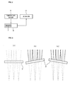
- FIG. 1 is a schematic diagram of a display device having an actuator for improving the resolution thereof according to an example embodiment of the present invention
- FIG. 2 is a block diagram of a controller of a display device according to an example embodiment of the present invention.
- FIG. 3 illustrates an operation of an actuator in a display device according to an example embodiment of the present invention
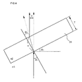
- FIG. 4 illustrates an operating principle of a light transmission plate of a display device according to an example embodiment of the present invention
- FIGs. 5 and 6 illustrate a shift of light projected on a screen according to movement of a light transmission plate in a display device
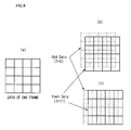
- FIG. 7 illustrates an image of one frame that is divided into a first image and a second image according to an example embodiment of the present invention
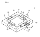
- FIG. 8 is a perspective view of an actuator according to an example embodiment of the present invention.
- FIG. 9 is an exploded perspective view of an actuator according to an example embodiment of the present invention.
- FIG. 10 is an exploded bottom perspective view of a driving device of an actuator according to an example embodiment of the present invention.
- FIG. 11 is an exploded perspective view of a holding device of an actuator according to an example embodiment of the present invention.
- FIG. 12 is a side view of the driving device of an actuator according to an example embodiment of the present invention.
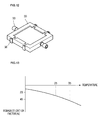
- FIG. 13 is a graph illustrating a variation of a demagnetization factor with respect to temperature of a magnet
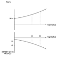
- FIG. 14 is a graph illustrating a demagnetization characteristic of a magnet when a gain value applied to an actuator is increased according to temperature.
- FIG. 15 is a flowchart illustrating a method of controlling a display device according to an example embodiment of the present invention.
- a display device having an actuator for improving the resolution thereof will be described below.
- a resolution of the display device can be stably increased by minimizing the influence of temperature on the actuator.
- Resolution relates to a number of pixels used to express an image. Resolution may be used as a scale to represent precision in displaying the image. To improve resolution, display devices may use a physical method of increasing the number of pixels. However, embodiments of the present invention may improve the resolution of the display device using a human visual characteristic.
- Embodiments of the present invention may display an image with a resolution higher than a physical resolution.
- an image of one frame may be divided into a first image signal and a second image signal.
- the first image signal and the second image signal are displayed on a first location and a second location of a screen, respectively.
- a human can recognize the resolution as being improved, according to a human visual characteristic (or human visual characteristics).
- first location and the second location of the screen may be spaced apart from each other by less than or more than one pixel in a vertical, horizontal or diagonal direction.
- An actuator may be used to shift the displaying locations of the first and second images such that they are displayed at the first and second locations, respectively.
- the actuator may include a light transmission material such that a light path varies when the location and/or an angle of the light transmission material is changed.
- FIG. 1 is a schematic diagram of a display device having an actuator for improving the resolution thereof according to an example embodiment of the present invention.
- Other embodiments and configurations are also within the scope of the present invention.
- FIG. 1 shows a digital light processing (DLP) optical system according to an example embodiment of the present invention.
- the DLP optical system includes a lamp 17 for emitting (or providing) light, a rod lens 18 (or light tunnel) for guiding the light emitted from the lamp 17, and a color wheel 19 for dividing white light from the rod lens 18 into a red (R) light, a green (G) light, and a blue (B) light.
- the DLP optical system further includes a condensing lens 13 for condensing the lights from the color wheel 19, a prism 15 for reflecting the light from the condensing lens 13 and a digital micromirror device (DMD) 14 for projecting the reflected light onto a screen 12.
- DMD digital micromirror device
- the DLP optical system may include an actuator 11 (or light regulator) for shifting the light reflected from the DMD 14 according to time variation, and a projection lens 16 for magnifying and projecting the light from the actuator 11 onto the screen 12.
- an actuator 11 or light regulator
- a projection lens 16 for magnifying and projecting the light from the actuator 11 onto the screen 12.
- the DLP optical system may further include a temperature sensor 9 disposed near the actuator 11 and a controller 8 for controlling the actuator 11 according to the temperature sensed by the temperature sensor 9.
- FIG. 2 is a block diagram of a controller of a display device according to an example embodiment of the present invention. More specifically, FIG. 2 relates to the controller 8 shown in FIG. 1. Other embodiments and configurations are also within the scope of the present invention.
- the controller 8 may include a memory 7 for storing gain values depending on temperature.
- the controller 8 may read the stored gain values from the memory 7 according to the temperature detected by the temperature sensor 9.
- the controller 8 controls the actuator 11 according to the gain values based on the sensed temperature.
- the actuator 11 may be driven by a magnet. Since the magnet has a demagnetization characteristic according to temperature, the actual gain value may change according to time when the actuator 11 is driven at a constant gain value. For example, if the temperature increases, the magnetic force decreases. Therefore, the gain value has to increase according to the temperature so as to drive the actuator 11 constantly.
- the controller 8 may drive the actuator 11 while changing the gain value according to the temperature change.
- the white light emitted (or provided) from the lamp 17 may be focused by an inner curvature of a reflector, and the focused light may pass through the rod lens 18.
- the rod lens 18 may be provided by attaching four small and elongated mirrors to one another. The light passing through the rod lens 18 may be scattered and reflected so that brightness is uniformly distributed.
- the brightness of light is uniform so as to obtain a uniform brightness of light that will be finally projected onto the screen 12.
- the rod lens 18 performs this function and thus is an optical element of the projection type display device.
- the light passing through the rod lens 18 is transmitted through the color wheel 19 for color separation.
- the color wheel 19 rotates according to a vertical synchronization of the image.
- the light passes through the condensing lens 13 and is reflected by the prism 15 such that the light is directed to the DMD 14.
- the prism 15 may totally reflect or transmit the light depending on an incident angle of the light.
- the light incident on the DMD 14 may be redirected toward the screen 12 depending on the ON/OFF state of the micromirrors of the DMD 14, which are controlled in response to sampled pixel values.
- the DMD 14 changes into the ON-state or the OFF-state depending on the image signals inputted from a signal processor (not shown). Through these procedures, a predetermined image may be formed.
- the image reflected from the DMD 14 and projected on the screen 12 passes through the actuator 11 and the projection lens 16. The image is enlarged and projected onto the screen 12.
- the actuator 11 may be disposed between the prism 15 and the projection lens 16.
- the actuator 11 may also be disposed between the screen 12 and the projection lens 16. Still further, the actuator 11 may be disposed between the DMD 14 and the prism 15.
- the light may be projected onto different locations of the screen 12 depending on the periodical change in the locations and/or angles of the actuator 11.
- the actuator 11 may be controlled by the controller 8. More specifically, the controller 8 reads a gain value from the memory 7 according to the temperature sensed by the temperature sensor 9 and changes the gain value of the actuator 11, if necessary.
- the actuator 11 may be driven even though the temperature is changed so as to have a projected image at a constant location.
- the image forming device of FIG. 1 receives the first image signal and the second image signal, which are provided by dividing an image of one frame at the signal processor and forms the first image and the second image by the R, G and B composition.
- the image forming device may include the color wheel 19, the condensing lens 13 and the DMD 14. After the image signal of one frame is divided into a plurality of image signals, the plurality of image signals are combined into a plurality of images and are then displayed.
- a displaying time of one image may be calculated by dividing a displaying time of a one-frame image by the number of images.
- the image signal of one frame may be divided into the first and second image signals, and the first and second image signals may be combined into the first and second images that are then displayed on the first and second locations of the screen, respectively. Through these procedures, viewers can recognize an improved resolution.
- the image signal of one frame may be divided into more image images.
- FIG. 3 illustrates an operation of an actuator of a display device according to an example embodiment of the present invention. Other embodiments and configurations are also within the scope of the present invention. More specifically, FIG. 3 illustrates a light transmission plate 31 of the actuator 11.
- FIG. 3(a) shows a state of no light transmission plate 31 or no movement of the light transmission plate 31.
- the image projected from the prism or the projection lens is displayed at a same location of the screen.
- FIG. 3(b) shows a state of the light transmission plate 31 being rotated in a counterclockwise direction.
- FIG. 3(c) shows a state of the light transmission plate 31 being rotated in a clockwise direction.
- the image may be refracted while passing through the light transmission plate 31, such that the image is displayed onto different locations of the screen.
- the light transmission plate 31 operating as an optical path changing device projects the image
- the projected image is displayed onto different locations of the screen depending on movement of the light transmission plate 31.
- the light transmission plate 31 may operate as an image shifting device to make the image display onto different locations of the screen.
- FIG. 4 illustrates an operating principle of a light transmission plate operating as an image shifting device of a display device according to an example embodiment of the present invention.
- Other embodiments and configurations are also within the scope of the present invention.
- a movement degree of the light on the screen 12 can be calculated based on thickness, tilt angle (light incident angle), and refractive index of the light transmission plate 31.
- the thickness, tilt angle and refractive index of the light transmission plate 31 can be selected based on the required movement degree of the light on the screen 12.
- the optical path difference D between the lights passing through the light transmission plate 31 may determine the shift of the lights displayed on the screen 12, depending on magnification of the projection lens.
- the refractive index of the light transmission plate 31 may fall within a range from 1.4 to 2.0, for example. Other ranges and values of the refractive index are also within the scope of the present invention.
- Embodiments of the present invention may use the light transmission plate and the light refraction to make the optical path difference D.
- a reflection mirror may be used to change the optical path. That is, a reflection mirror may be placed on or along the optical path, and the path of the light reflected according to the angle of the reflection mirror may be changed by the changing of the reflection angle of the light.
- the change of the optical path may be sensitive to the change in the angle of the reflection mirror as compared with a method of changing the optical path using light refraction. Therefore, precise control may be used if light reflection is used to change the optical path.
- a shift degree of the image may be more than or less than a size of one pixel.
- the optical path changing device or image shifting device
- the optical path changing device (or image shifting device) may be precisely controlled so that the image projected from the projection lens can be shifted within a small range. Therefore, the optical path changing device (or image shifting device) using the light transmission plate may have advantages in that it can be easily controlled and error probability may be greatly reduced.
- FIGs. 5 and 6 illustrate a shift of light projected onto a screen according to movement of a light transmission plate in a display device according to an example embodiment of the present invention.
- Other embodiments and configurations are also within the scope of the present invention.
- the light transmission plate 31 periodically moves and therefore the location of the image on the screen 12 moves.
- a double resolution can be recognized using the same number of pixels.
- the image signal of one frame may be split into the first and second image signals. Then, when the image of one frame is displayed, the first and second image signals are combined and displayed in sequence.
- the image information may be split into first image information and second image information, and then the first image information and the second image information are respectively displayed at the first and second locations on the screen with each image information being displayed for 1/120 of a second.
- the display locations of the first image (odd data) and the second image (even data) are shifted in a diagonal direction.
- the display locations of the first image (odd data) and the second image (even data) are shifted in a horizontal direction.
- FIG. 6 illustrates locations of the image displayed onto the screen depending on time in a rhombus pixel structure.
- FIG. 7 is an exemplary view of a first image and a second image split from an image of one frame according to an example embodiment of the present invention. Other embodiments and configurations are also within the scope of the present invention.
- the image of one frame can be split into the first image and the second image, and the first image and the second image can be split depending on the locations of the pixels.
- the locations at which the first image (odd data) and the second image (even data) are displayed can be shifted by the light transmission plate 31.
- FIG. 8 is a perspective view of an actuator according to an example embodiment of the present invention.
- FIG. 9 is an exploded perspective view of the actuator shown in FIG. 8.
- Other embodiments and configurations are also within the scope of the present invention.
- FIG. 10 is an exploded bottom perspective view of a driving device of an actuator according to an example embodiment of the present invention.
- FIG. 11 is an exploded perspective view of a holding device of an actuator according to an example embodiment of the present invention.
- Other embodiments and configurations are also within the scope of the present invention.
- the actuator 11 includes a holding device 20 and a driving device 30.
- the holding device 20 may be disposed on an optical path between the image forming device and the screen 12 and has a holding portion 21 at one side. Although a screw hole is illustrated in the drawings, other devices or mechanisms may also be used hold the holding device 20 within the display device.
- the actuator 11 may be firmly held to the holding device 20 on the optical path.
- a magnet 23 and a yoke 22 are formed at one side of the holding device 20.
- the magnet 23 and the yoke 23 may be formed on one side or both sides of the holding device 20.
- the magnet 23 and the yoke 22 may be formed on an inner side of the holding device 20.
- the magnet 23 may be a dipole magnet having north (N) and south (S) poles.
- the magnet 23 may be a monopole magnet or a multipole magnet.
- the magnet 23 may drive the driving device 30 by using a magnetic field.
- the yoke 22 may form a passage of a magnetic field to increase the efficiency of the magnetic field.
- the driving device 30 may be rotatably coupled to an inside of the holding device 20.
- the driving device 30 may be formed in a rectangular or rhombus shape and surround the optical path.
- the driving device 30 may have a structure suitable for holding the light transmission plate 31.
- the light transmission plate 31 is a light transmitting element that rotates at a predetermined angle for a short time and changes the display location of the image.
- the light transmission plate 31 may be perpendicular to the optical path or inclined at a predetermined angle. The angle of the light incident on the light transmission plate 31 may be periodically changed.
- the driving device 30 may include shafts 32 on both sides (i.e., opposite sides) and may be rotatably connected to shaft inserting grooves 27 on the holding device 20.
- the driving device 30 may further include first and second bearings 33 and 36.
- the shaft 32 serves as a rotational axis of the driving device 30 and/or the light transmission plate 31.
- the rotational axis may be perpendicular to the optical path.
- the first bearing 33 may be formed in an approximately cylindrical shape and the shaft 32 may be inserted into the first bearing 33.
- the first bearing 33 may be disposed on the shaft inserting groove 27 of the holding device 20.
- the second bearing 36 makes an outer diameter of the driving device 30 so large that the driving device 30 may be caught by an inner surface of the holding device 20.
- the driving device 30 may be inserted into the holding device 20 such that it cannot move in a left direction due to the second bearing 36.
- a leaf spring 24 may be formed at a right side of the first bearing 33 such that the driving device 30 can not move in a right direction.
- An elasticity of the leaf spring 24 may secure a proper movement while holding the driving device 30 such that the driving device 30 can rotate smoothly.
- the leaf spring 24 may support the driving device 30.
- a first cover 25 and a second cover 26 are disposed on upper sides of the first and second bearings 33 and 36 so that the driving device 30 may not be released upwardly.
- the first cover 25 is coupled to the driving device 30 by two screws, for example, and the second cover 26 is partially coupled to the driving device 30 by one screw, for example.
- the covers 25, 26 may secure a proper movement in order to allow the driving device 30 to rotate smoothly.
- the second cover 26 may have a proper elastic force and its operation may be similar to operation of the leaf spring 24.
- the second cover 26 may serve as an elastic member that can hold (or fix) the driving device 30 to the holding device 20 while securing proper movement of the driving device 30.
- a coil 35 may be provided at a side of the driving device 30 (i.e., a side opposing the magnet 23 formed on the holding device 20).
- a coil holder 38 may be provided at a side of the driving device 30 as shown in FIG. 10 such that the coil 35 is supported and held by the coil holder 38.
- the coil 35 may be formed in a rectangular shape or an oval shape, for example.
- the driving device 30 can move around the magnet 23 along a direction of current.
- the driving device 30 rotates about the rotational axis in a clockwise or counterclockwise direction depending on the direction of the current applied to the coil 35.
- a magnet may be provided at a side of the driving device 30.
- a coil holder may be provided at a side of the holding device 20 and opposing the magnet, and a coil may be supported by the coil holder.
- the light transmission plate 31 may be coupled to the driving device 30.
- the light transmission plate 31 may be positioned on a protrusion 39 formed at an inside of the driving device 30, and then held (or fixed) by a supporting member 37.
- FIG. 9 shows a shape of the protrusion 39.
- the light transmission plate 31 may be injected together with the driving device 30.
- the light transmission plate 31 can then be held to the driving device 30 without any additional supporting member 37.
- a stopper 28 may be provided at an inside of the holding device 20 so as to limit a rotational angle of the driving device 30.
- the rotational range of the driving device 30 may be limited to below a predetermined angle under an external impact or an erroneous operation or an excessive operation.
- the actuator 11 may be disposed on the optical path of the display device and may be rotated due to interaction of the coil 35 and the magnet 23 depending on the applied control current.
- the rotational range of the driving device 30 can be set within ⁇ 0.75°, for example, and can be rotated such that it is periodically disposed at the first location and the second location.
- the driving device 30 may rotate at least one time while an image signal of one frame is applied. Other rotational ranges of the driving device 30 may also be provided.
- FIG. 13 is a graph illustrating a variation of a demagnetization factor with respect to temperature of a magnet. Other graphs and demagnetization factors may also be used.
- the magnet 23 has a demagnetization factor that varies with temperature. That is, when the temperature of the magnet 23 increases, the demagnetization factor increases so that the magnetic force is reduced.
- the actuator 11 Since the actuator 11 operates at a high speed, the ambient temperature increases with the operation time and thus the magnetic force of the magnet 23 changes.
- the operation state of the actuator 11 is changed according to the temperature. That is, if the temperature increases, the rotational speed or rotational angle of the driving device 30 may be reduced.
- FIG. 14 is a graph illustrating a demagnetization characteristic of a magnet when a gain value applied to an actuator is increased according to temperature.
- the controller 8 may read a gain value from the memory 7 according to the temperature sensed by the temperature sensor 9 and drive the actuator 11. Therefore, the actuator 11 can operate stably even though the temperature is changed.
- Demagnetization factor % 0.2 ⁇ temp - 2 ⁇ P c - 4 , where temp represents the temperature of the magnet, and P C represents a permeance coefficient according to characteristics of the magnet.
- the gain value to be corrected according to the temperature increase or decrease from a reference temperature may be expressed by Equation (4).
- the reference temperature may be a room temperature (25°C).
- ⁇ Gain Varied Demagnetization Factor % 100 ⁇ rGain , where ⁇ Gain is a gain value to be increased or decreased according to the temperature change, and the varied demagnetization factor is a difference between the demagnetization factor at a previous temperature and the demagnetization factor at a current temperature, and rGain is a gain value applied at the reference temperature.
- the gain value is an analog voltage value for driving the actuator 11 through the control of the actuator 11, and ⁇ Gain is a gain value to be added according to reduction of the demagnetization factor.
- the gain value to be applied to the actuator 11 according to the varied demagnetization factor (%) and ⁇ Gain can be expressed by the following Equation (5):
- Gain rGain + ⁇ Gain
- the controller 8 may calculate the demagnetization factor (%) according to the temperature sensed by the temperature sensor 9 using Equation (1) and then the controller 8 may calculate ⁇ gain by comparing the calculated demagnetization factor with the demagnetization factor at the reference temperature.
- the gain value applied to the actuator 11 may be calculated by Equation (5).
- the actuator 11 may operate stably regardless of the temperature variation.
- the gain value according to the temperature is stored in the memory 7, the gain value to be applied to the actuator 11 according to the temperature detected by the temperature sensor 9 can be calculated.
- FIG. 15 is a flowchart illustrating a method of controlling a display device according to an example embodiment of the present invention.
- Other embodiments and configurations are also within the scope of the present invention.
- an ambient temperature around the actuator is detected when a user inputs a power-on command.
- a temperature compensation gain is adjusted in operation S104.
- Embodiments of the present invention may improve an image quality of a projection type display device by preventing an actuator from being abnormally operated due to an increased temperature.
- Embodiments of the present invention may be directed to a display device that substantially obviates one or more problems.
- Embodiments of the present invention may provide a display device having an actuator that can be driven without influence of an internal temperature, thereby improving the resolution thereof.
- Embodiments of the present invention may provide a projection type display device having high resolution.
- Embodiments of the present invention may provide a display device that includes a light source, an image forming unit (or device), a projection lens, an activator, a temperature sensor and a controller.
- the light source may emit a light.
- the image forming unit may form an image using the emitted light and an inputted image signal.
- the projection lens may project the formed image onto a screen.
- the actuator may shift the image displayed on the screen.
- the temperature sensor may detect an ambient temperature around the actuator.
- the controller may drive the actuator according to the detected temperature.
- Embodiments of the present invention may provide a display device that includes a light source, an image forming unit, a projection lens, an activator, a temperature sensor and a controller.
- the light source may emit a light.
- the image forming unit may form an image using the emitted light and an inputted image signal.
- the projection lens may project the formed image onto a screen.
- the actuator may be disposed on an optical path through which the image is projected to change the optical path.
- the temperature sensor may detect a temperature.
- the controller may vary a voltage applied to the actuator according to the detected temperature. The controller may increase the applied voltage when the detected temperature is higher than a set temperature. The controller may decrease the applied voltage when the detected temperature is lower than the set temperature.
- Embodiments of the present invention may provide a displaying method that includes emitting a light, forming an image using the emitted light and an inputted image signal, and periodically changing a traveling direction of the image by varying a driving signal applied to an actuator having a light transmission plate according to a temperature.
- the method may also include projecting the image on a screen.
- any reference in this specification to "one embodiment,” “an embodiment,” “example embodiment,” etc. means that a particular feature, structure, or characteristic described in connection with the embodiment is included in at least one embodiment of the present invention.
- the appearances of such phrases in various places in the specification are not necessarily all referring to the same embodiment.
Landscapes
- Physics & Mathematics (AREA)
- Engineering & Computer Science (AREA)
- General Physics & Mathematics (AREA)
- Optics & Photonics (AREA)
- Computer Hardware Design (AREA)
- Theoretical Computer Science (AREA)
- Multimedia (AREA)
- Signal Processing (AREA)
- Mechanical Engineering (AREA)
- Mechanical Light Control Or Optical Switches (AREA)
- Projection Apparatus (AREA)
- Electroluminescent Light Sources (AREA)
Applications Claiming Priority (1)
| Application Number | Priority Date | Filing Date | Title |
|---|---|---|---|
| KR1020060015884A KR20070082800A (ko) | 2006-02-17 | 2006-02-17 | 디스플레이장치 |
Publications (2)
| Publication Number | Publication Date |
|---|---|
| EP1821283A2 true EP1821283A2 (de) | 2007-08-22 |
| EP1821283A3 EP1821283A3 (de) | 2009-04-29 |
Family
ID=38022827
Family Applications (1)
| Application Number | Title | Priority Date | Filing Date |
|---|---|---|---|
| EP06018006A Withdrawn EP1821283A3 (de) | 2006-02-17 | 2006-08-29 | Anzeigevorrichtung und Anzeigeverfahren |
Country Status (4)
| Country | Link |
|---|---|
| US (1) | US20070195279A1 (de) |
| EP (1) | EP1821283A3 (de) |
| KR (1) | KR20070082800A (de) |
| CN (1) | CN101025549A (de) |
Cited By (1)
| Publication number | Priority date | Publication date | Assignee | Title |
|---|---|---|---|---|
| EP2560378A3 (de) * | 2011-08-16 | 2013-08-14 | Samsung Electronics Co., Ltd. | Projektor mit Verschiebung zwischen optischem Projektionssystem und Anzeigeeinheit |
Families Citing this family (11)
| Publication number | Priority date | Publication date | Assignee | Title |
|---|---|---|---|---|
| CN101661214B (zh) * | 2008-08-27 | 2011-06-08 | 鸿富锦精密工业(深圳)有限公司 | 投影机 |
| US8902130B2 (en) * | 2010-04-20 | 2014-12-02 | Panasonic Corporation | Image display device |
| JP5540991B2 (ja) * | 2010-08-19 | 2014-07-02 | ソニー株式会社 | 光学装置および表示装置 |
| CN102231010A (zh) * | 2011-06-15 | 2011-11-02 | 杭州晶景光电有限公司 | 用于微型投影光引擎的宽尺寸面光源整形系统 |
| US9176536B2 (en) | 2011-09-30 | 2015-11-03 | Apple, Inc. | Wireless display for electronic devices |
| US9810942B2 (en) | 2012-06-15 | 2017-11-07 | Apple Inc. | Quantum dot-enhanced display having dichroic filter |
| JP6520432B2 (ja) * | 2015-06-09 | 2019-05-29 | セイコーエプソン株式会社 | 光学デバイスおよび画像表示装置 |
| JP6569329B2 (ja) * | 2015-06-29 | 2019-09-04 | セイコーエプソン株式会社 | 光学デバイスおよび画像表示装置 |
| JP7371627B2 (ja) * | 2018-07-20 | 2023-10-31 | ソニーグループ株式会社 | 画像表示装置及び画像表示方法 |
| JP7604963B2 (ja) * | 2021-03-17 | 2024-12-24 | セイコーエプソン株式会社 | 光源装置及びプロジェクター |
| US12468017B2 (en) * | 2021-10-15 | 2025-11-11 | Seyond, Inc. | Integrated mirror motor galvanometer |
Family Cites Families (10)
| Publication number | Priority date | Publication date | Assignee | Title |
|---|---|---|---|---|
| JPH0743672A (ja) * | 1993-08-02 | 1995-02-14 | Sony Corp | 光学素子回動装置、ソレノイド及び液晶プロジェクター |
| US6002452A (en) * | 1995-06-08 | 1999-12-14 | Texas Instruments Incorporated | Sequential color display system with spoke synchronous frame rate conversion |
| JPH11160434A (ja) * | 1997-11-26 | 1999-06-18 | Mitsubishi Electric Corp | 距離測定装置 |
| DK1305807T3 (da) * | 2000-08-03 | 2010-03-08 | Direct Thrust Designs Ltd | Lineær elektrisk kortslagsaktuator |
| US7183633B2 (en) * | 2001-03-01 | 2007-02-27 | Analog Devices Inc. | Optical cross-connect system |
| JP2004198636A (ja) * | 2002-12-17 | 2004-07-15 | Olympus Corp | 光学系及びそれを用いた光学装置 |
| KR100629534B1 (ko) * | 2004-02-12 | 2006-09-27 | 엘지전자 주식회사 | 온도변화에 따른 색오차 보정방법 및 장치 |
| CA2560084C (en) * | 2004-03-16 | 2012-07-03 | Sign-Tronic Ag | Method for establishing a light beam with substantially constant luminous intensity |
| KR20050114470A (ko) * | 2004-06-01 | 2005-12-06 | 엘지전자 주식회사 | 해상도 향상 장치 |
| EP1864490B1 (de) * | 2005-03-30 | 2013-02-20 | LG Electronics Inc. | Kühlsystem für einen schlanken Projektor |
-
2006
- 2006-02-17 KR KR1020060015884A patent/KR20070082800A/ko not_active Withdrawn
- 2006-08-29 EP EP06018006A patent/EP1821283A3/de not_active Withdrawn
- 2006-08-31 US US11/513,151 patent/US20070195279A1/en not_active Abandoned
- 2006-09-07 CN CNA2006101272047A patent/CN101025549A/zh active Pending
Cited By (1)
| Publication number | Priority date | Publication date | Assignee | Title |
|---|---|---|---|---|
| EP2560378A3 (de) * | 2011-08-16 | 2013-08-14 | Samsung Electronics Co., Ltd. | Projektor mit Verschiebung zwischen optischem Projektionssystem und Anzeigeeinheit |
Also Published As
| Publication number | Publication date |
|---|---|
| CN101025549A (zh) | 2007-08-29 |
| EP1821283A3 (de) | 2009-04-29 |
| KR20070082800A (ko) | 2007-08-22 |
| US20070195279A1 (en) | 2007-08-23 |
Similar Documents
| Publication | Publication Date | Title |
|---|---|---|
| US20050264501A1 (en) | Display device | |
| US6877862B2 (en) | Projector | |
| EP1821283A2 (de) | Anzeigevorrichtung und Anzeigeverfahren | |
| US20050128438A1 (en) | Actuator for improvement of resolution | |
| US7270417B2 (en) | Display device and display method in which resolution improving apparatus is provided for project-type display device | |
| JP2980599B2 (ja) | マグネットを利用したビデオカメラの手振れ補正装置 | |
| US7762669B2 (en) | Display device for improving an image resolution of projection-type display device | |
| US9835936B2 (en) | Angle adjustment apparatus and projection display apparatus | |
| US7290884B2 (en) | Display device having resolution improving apparatus for project-type display device | |
| KR20050113326A (ko) | 해상도 향상 장치 그리고 이를 이용한 디스플레이장치 | |
| US20060221309A1 (en) | Projection type of image displaying apparatus | |
| US20050264547A1 (en) | Display device | |
| EP3707545B1 (de) | Projektor und betriebsverfahren dafür | |
| KR20070037239A (ko) | 엑츄에이터 | |
| KR20070032270A (ko) | 디스플레이장치 | |
| KR20070032268A (ko) | 디스플레이장치 | |
| KR100794769B1 (ko) | 오프빔 차단부재가 있는 픽셀촉진장치 | |
| KR20070035471A (ko) | 디스플레이장치 | |
| KR20070032269A (ko) | 디스플레이장치 | |
| KR20050117100A (ko) | 해상도 향상 장치 | |
| KR20070037227A (ko) | 엑츄에이터 | |
| KR20070037237A (ko) | 엑츄에이터 | |
| KR20070037236A (ko) | 엑츄에이터 |
Legal Events
| Date | Code | Title | Description |
|---|---|---|---|
| PUAI | Public reference made under article 153(3) epc to a published international application that has entered the european phase |
Free format text: ORIGINAL CODE: 0009012 |
|
| 17P | Request for examination filed |
Effective date: 20060829 |
|
| AK | Designated contracting states |
Kind code of ref document: A2 Designated state(s): AT BE BG CH CY CZ DE DK EE ES FI FR GB GR HU IE IS IT LI LT LU LV MC NL PL PT RO SE SI SK TR |
|
| AX | Request for extension of the european patent |
Extension state: AL BA HR MK YU |
|
| PUAL | Search report despatched |
Free format text: ORIGINAL CODE: 0009013 |
|
| AK | Designated contracting states |
Kind code of ref document: A3 Designated state(s): AT BE BG CH CY CZ DE DK EE ES FI FR GB GR HU IE IS IT LI LT LU LV MC NL PL PT RO SE SI SK TR |
|
| AX | Request for extension of the european patent |
Extension state: AL BA HR MK RS |
|
| RIC1 | Information provided on ipc code assigned before grant |
Ipc: H04N 5/74 20060101ALI20090326BHEP Ipc: H02K 33/16 20060101ALI20090326BHEP Ipc: G09G 3/00 20060101ALI20090326BHEP Ipc: H02P 27/02 20060101ALI20090326BHEP Ipc: H02K 7/065 20060101ALI20090326BHEP Ipc: H01F 7/06 20060101ALI20090326BHEP Ipc: G02B 27/09 20060101ALI20090326BHEP Ipc: G02B 27/28 20060101ALI20090326BHEP Ipc: G02B 27/10 20060101ALI20090326BHEP Ipc: G02B 27/00 20060101ALI20090326BHEP Ipc: G09G 3/34 20060101AFI20070529BHEP |
|
| AKX | Designation fees paid | ||
| STAA | Information on the status of an ep patent application or granted ep patent |
Free format text: STATUS: THE APPLICATION IS DEEMED TO BE WITHDRAWN |
|
| 18D | Application deemed to be withdrawn |
Effective date: 20091030 |
|
| REG | Reference to a national code |
Ref country code: DE Ref legal event code: 8566 |