EP1821374A2 - Vorrichtung und Verfahren zum Erhitzen einer infrarotaktivierten Nahtabdichtung - Google Patents
Vorrichtung und Verfahren zum Erhitzen einer infrarotaktivierten Nahtabdichtung Download PDFInfo
- Publication number
- EP1821374A2 EP1821374A2 EP07250660A EP07250660A EP1821374A2 EP 1821374 A2 EP1821374 A2 EP 1821374A2 EP 07250660 A EP07250660 A EP 07250660A EP 07250660 A EP07250660 A EP 07250660A EP 1821374 A2 EP1821374 A2 EP 1821374A2
- Authority
- EP
- European Patent Office
- Prior art keywords
- infrared
- splice
- heating
- heat
- cooling
- Prior art date
- Legal status (The legal status is an assumption and is not a legal conclusion. Google has not performed a legal analysis and makes no representation as to the accuracy of the status listed.)
- Pending
Links
- 238000010438 heat treatment Methods 0.000 title claims abstract description 91
- 238000000034 method Methods 0.000 title claims description 53
- 238000001816 cooling Methods 0.000 claims abstract description 43
- 238000009434 installation Methods 0.000 claims description 55
- 239000000853 adhesive Substances 0.000 claims description 19
- 230000001070 adhesive effect Effects 0.000 claims description 19
- 238000007789 sealing Methods 0.000 claims description 18
- 239000010410 layer Substances 0.000 claims description 13
- 239000000463 material Substances 0.000 claims description 13
- 230000005855 radiation Effects 0.000 claims description 12
- 239000012790 adhesive layer Substances 0.000 claims description 10
- 229910052736 halogen Inorganic materials 0.000 claims description 10
- 150000002367 halogens Chemical class 0.000 claims description 10
- 239000010453 quartz Substances 0.000 claims description 10
- VYPSYNLAJGMNEJ-UHFFFAOYSA-N silicon dioxide Inorganic materials O=[Si]=O VYPSYNLAJGMNEJ-UHFFFAOYSA-N 0.000 claims description 10
- 239000004020 conductor Substances 0.000 claims description 8
- 239000006229 carbon black Substances 0.000 claims description 7
- 239000012809 cooling fluid Substances 0.000 claims description 7
- 230000003213 activating effect Effects 0.000 claims description 4
- 230000008569 process Effects 0.000 claims description 4
- 239000000112 cooling gas Substances 0.000 claims description 3
- 230000009977 dual effect Effects 0.000 claims description 3
- 238000007664 blowing Methods 0.000 claims description 2
- 230000000977 initiatory effect Effects 0.000 claims description 2
- 239000000049 pigment Substances 0.000 claims description 2
- XLYOFNOQVPJJNP-UHFFFAOYSA-N water Substances O XLYOFNOQVPJJNP-UHFFFAOYSA-N 0.000 description 11
- 229920000642 polymer Polymers 0.000 description 9
- 239000000758 substrate Substances 0.000 description 9
- 238000004519 manufacturing process Methods 0.000 description 8
- RYGMFSIKBFXOCR-UHFFFAOYSA-N Copper Chemical compound [Cu] RYGMFSIKBFXOCR-UHFFFAOYSA-N 0.000 description 6
- 229910052802 copper Inorganic materials 0.000 description 6
- 239000010949 copper Substances 0.000 description 6
- 230000000694 effects Effects 0.000 description 6
- 239000000565 sealant Substances 0.000 description 6
- 238000010276 construction Methods 0.000 description 5
- 238000010521 absorption reaction Methods 0.000 description 4
- 230000008901 benefit Effects 0.000 description 4
- 238000009413 insulation Methods 0.000 description 4
- 238000012545 processing Methods 0.000 description 4
- 238000011084 recovery Methods 0.000 description 4
- 238000012546 transfer Methods 0.000 description 3
- 239000004952 Polyamide Substances 0.000 description 2
- 239000004411 aluminium Substances 0.000 description 2
- 229910052782 aluminium Inorganic materials 0.000 description 2
- XAGFODPZIPBFFR-UHFFFAOYSA-N aluminium Chemical compound [Al] XAGFODPZIPBFFR-UHFFFAOYSA-N 0.000 description 2
- 239000002826 coolant Substances 0.000 description 2
- 230000001351 cycling effect Effects 0.000 description 2
- 239000007789 gas Substances 0.000 description 2
- 229920001903 high density polyethylene Polymers 0.000 description 2
- 239000004700 high-density polyethylene Substances 0.000 description 2
- 239000000155 melt Substances 0.000 description 2
- 229920002647 polyamide Polymers 0.000 description 2
- 230000009467 reduction Effects 0.000 description 2
- 102100028022 E3 ubiquitin-protein ligase TRIM47 Human genes 0.000 description 1
- 101000649007 Homo sapiens E3 ubiquitin-protein ligase TRIM47 Proteins 0.000 description 1
- 241000872198 Serjania polyphylla Species 0.000 description 1
- ATJFFYVFTNAWJD-UHFFFAOYSA-N Tin Chemical compound [Sn] ATJFFYVFTNAWJD-UHFFFAOYSA-N 0.000 description 1
- 239000011358 absorbing material Substances 0.000 description 1
- 230000005540 biological transmission Effects 0.000 description 1
- 230000015556 catabolic process Effects 0.000 description 1
- 239000011248 coating agent Substances 0.000 description 1
- 238000000576 coating method Methods 0.000 description 1
- 239000004595 color masterbatch Substances 0.000 description 1
- 239000000356 contaminant Substances 0.000 description 1
- 230000008878 coupling Effects 0.000 description 1
- 238000010168 coupling process Methods 0.000 description 1
- 238000005859 coupling reaction Methods 0.000 description 1
- 230000001186 cumulative effect Effects 0.000 description 1
- 230000007423 decrease Effects 0.000 description 1
- 238000006731 degradation reaction Methods 0.000 description 1
- 230000001934 delay Effects 0.000 description 1
- 230000003467 diminishing effect Effects 0.000 description 1
- 230000007613 environmental effect Effects 0.000 description 1
- 230000002401 inhibitory effect Effects 0.000 description 1
- 238000003780 insertion Methods 0.000 description 1
- 230000037431 insertion Effects 0.000 description 1
- 239000007788 liquid Substances 0.000 description 1
- 238000002844 melting Methods 0.000 description 1
- 230000008018 melting Effects 0.000 description 1
- 229910052751 metal Inorganic materials 0.000 description 1
- 239000002184 metal Substances 0.000 description 1
- 238000012544 monitoring process Methods 0.000 description 1
- 239000002861 polymer material Substances 0.000 description 1
- 239000012812 sealant material Substances 0.000 description 1
- 238000005382 thermal cycling Methods 0.000 description 1
Images

Classifications
-
- H—ELECTRICITY
- H02—GENERATION; CONVERSION OR DISTRIBUTION OF ELECTRIC POWER
- H02G—INSTALLATION OF ELECTRIC CABLES OR LINES, OR OF COMBINED OPTICAL AND ELECTRIC CABLES OR LINES
- H02G1/00—Methods or apparatus specially adapted for installing, maintaining, repairing or dismantling electric cables or lines
- H02G1/14—Methods or apparatus specially adapted for installing, maintaining, repairing or dismantling electric cables or lines for joining or terminating cables
-
- B—PERFORMING OPERATIONS; TRANSPORTING
- B29—WORKING OF PLASTICS; WORKING OF SUBSTANCES IN A PLASTIC STATE IN GENERAL
- B29C—SHAPING OR JOINING OF PLASTICS; SHAPING OF MATERIAL IN A PLASTIC STATE, NOT OTHERWISE PROVIDED FOR; AFTER-TREATMENT OF THE SHAPED PRODUCTS, e.g. REPAIRING
- B29C65/00—Joining or sealing of preformed parts, e.g. welding of plastics materials; Apparatus therefor
- B29C65/02—Joining or sealing of preformed parts, e.g. welding of plastics materials; Apparatus therefor by heating, with or without pressure
- B29C65/14—Joining or sealing of preformed parts, e.g. welding of plastics materials; Apparatus therefor by heating, with or without pressure using wave energy, i.e. electromagnetic radiation, or particle radiation
-
- H—ELECTRICITY
- H02—GENERATION; CONVERSION OR DISTRIBUTION OF ELECTRIC POWER
- H02G—INSTALLATION OF ELECTRIC CABLES OR LINES, OR OF COMBINED OPTICAL AND ELECTRIC CABLES OR LINES
- H02G1/00—Methods or apparatus specially adapted for installing, maintaining, repairing or dismantling electric cables or lines
- H02G1/12—Methods or apparatus specially adapted for installing, maintaining, repairing or dismantling electric cables or lines for removing insulation or armouring from cables, e.g. from the end thereof
- H02G1/1275—Methods or apparatus specially adapted for installing, maintaining, repairing or dismantling electric cables or lines for removing insulation or armouring from cables, e.g. from the end thereof by applying heat
- H02G1/128—Methods or apparatus specially adapted for installing, maintaining, repairing or dismantling electric cables or lines for removing insulation or armouring from cables, e.g. from the end thereof by applying heat using radiant energy, e.g. a laser beam
-
- H—ELECTRICITY
- H05—ELECTRIC TECHNIQUES NOT OTHERWISE PROVIDED FOR
- H05B—ELECTRIC HEATING; ELECTRIC LIGHT SOURCES NOT OTHERWISE PROVIDED FOR; CIRCUIT ARRANGEMENTS FOR ELECTRIC LIGHT SOURCES, IN GENERAL
- H05B3/00—Ohmic-resistance heating
- H05B3/0033—Heating devices using lamps
- H05B3/0038—Heating devices using lamps for industrial applications
- H05B3/0061—Heating devices using lamps for industrial applications for metal treatment
-
- H—ELECTRICITY
- H05—ELECTRIC TECHNIQUES NOT OTHERWISE PROVIDED FOR
- H05B—ELECTRIC HEATING; ELECTRIC LIGHT SOURCES NOT OTHERWISE PROVIDED FOR; CIRCUIT ARRANGEMENTS FOR ELECTRIC LIGHT SOURCES, IN GENERAL
- H05B2203/00—Aspects relating to Ohmic resistive heating covered by group H05B3/00
- H05B2203/032—Heaters specially adapted for heating by radiation heating
Definitions
- This invention relates to apparatus and a method for heating an infrared-initiated splice seal or a similar structure.
- infrared-initiated splice seal is meant an arrangement, for protecting and sealing otherwise exposed wire splices, of a kind whose installation relies on heating using infrared energy to commence a process of fitting the arrangement about a splice.
- Wire splices are commonly used in electrical harnesses in the automotive industry.
- the invention is of particular benefit in such applications, although it is applicable in other situations in which it is needed to seal splices in a production environment.
- each wire to be spliced has its electrically insulative covering removed eg. at one end, or at one or more other locations to expose bare electrically conductive wire.
- the wires to be joined are then arranged as required with all of the exposed bare wires essentially parallel and overlapping each other.
- a preferred means for protecting the nugget and sealing out moisture and other contaminants is to encase the nugget in a dimensionally recoverable tubing which has a sealant/adhesive interior layer ("liner"). Typically, heat is applied to cause the sealant/adhesive liner to flow, while simultaneously causing the tubing to heat-recover (shrink) about the nugget.
- liner sealant/adhesive interior layer
- the tubing shrinks around the exposed wires and the adhesive/sealant flows within the tubing to cover and seal the exposed wires.
- the adhesive/sealant also flows along the wires to contact and cover a portion of the unstripped, electrically insulative wire covering. This provides a seal over the entire length of the exposed wires and the splice nugget, up to and including the beginning of the insulative wire covering, and thus prevents water from entering the splice and/or from flowing along the conductors inside the wire insulation.
- Wire butt splices and wire splices to ring terminals or other termination devices can also be sealed and protected in this way.
- connectors may be sealed against water ingress and bundles of wires blocked using adhesive inserts in combination with heat shrink tubing.
- Heat-shrinkable splice seal sleeves comprise a heat-shrinkable outer jacket that is either clear or black with an adhesive liner that is clear.
- Various heating devices are available.
- Known dual-wall heat shrinkable splice seal sleeves for example Raychem RBK-ILS-125 (trade mark) splice seals available from Tyco Electronics, are particularly well suited for rapid installation when used in combination with customised application equipment, for example the Raychem RBK-ILS Mk2 heater/processor also available from Tyco.
- Such dual-wall heat-shrinkable-tubing splice seal products comprise a tubular construction having an outer crosslinked polymeric heat-shrinkable sleeve in combination with an inner heat-flowable adhesive/sealant liner.
- the tubing When heated, the tubing shrinks and the adhesive/sealant layer melts and flows.
- Such products are well known in a range of different materials and sizes and are used in various industries for environmental sealing of cable and wire splices.
- the products are installed by sliding the sleeve and liner over the area to be sealed and heating using a heat gun, flame, infrared, or other heat source to shrink the tubing.
- the minimum time taken to achieve a sealed splice depends on a number of factors including the number and size of the component wires that make up the splice, the size of the tube, the recovery temperature of the tube, the melting temperature of the adhesive liner, the viscosity of the liner at the recovery temperature, the hoop stress of the tubing at the recovery temperature, the temperature of the copper nugget, the type of heating device employed and its thermal characteristics.
- the invention as set out herein includes within its scope all such splices, seals and blocks as may be formed using dimensionally recoverable tubing having a liner that may be caused to flow on heating.
- the invention includes, in addition to the aforementioned structures, structures such as ring terminal seals, stub splice seals, various kinds of connector seal and various kinds of bundling block.
- splices For convenience herein all such structures are referred to as “splices” and, as the context requires, “splice seals", although in practice some of the structures, to which the invention relates, may not require actual splicing together of conductors or other filaments.
- Improved splice seal installation times can be achieved using a product having a clear jacket and black liner in combination with IR heating of appropriate wavelength.
- One such method of installation overcomes the problems of polymer damage and long installation times by rapid heat transfer to the adhesive liner using a radiant heat source, a clear polymer jacket that is substantially transparent to infrared radiation and a black adhesive liner that is infrared absorbing.
- To achieve maximum absorbtion by the liner preferably there is minimal absorption by the jacket (ie. absorption that is as close as possible to zero).
- the addition of energy absorbing materials to the jacket may retard the rate of sealing by the liner. To achieve rapid installation this conduction is best achieved by intimate interfacial bonding of jacket and liner which is maximised and most economically achieved in a coextruded product.
- the construction of the article is shown in Figure 1.
- the clear jacket allows transmission of a high proportion of the radiation which is then absorbed by the black liner, increases the rate of heating, accelerates the reduction of viscosity and decreases the installation time. Reduced absorption by the clear jacket may also reduce polymer damage due to heating.
- Tyco product ES1000 has a clear jacket and a clear liner.
- the jacket materials of these products are both based on high density polyethylene.
- the liner material is based on a polyamide adhesive.
- a heat shrink tube having a clear (that is substantially non-infrared-absorbing) jacket and black liner is based on the high density polyethylene jacket of the Tyco ES1000 product in combination with a polyamide liner, for example Tyco Type 2672, containing 0.5% added Wilson 6BK40, a colour masterbatch, which incorporates the equivalent of 0.0125% carbon black.
- the jacket and liner are coextruded to create an effective interface for heat transfer from the liner to the jacket.
- the most widely used heat source for installation of splice seals in a high volume automotive environment is the aforesaid RBK-ILS Mk2 processor, from Tyco.
- This comprises a retractable oven which uses hot wire filaments.
- Other oven configurations are available, for example the Model 19 belt heater also from Tyco.
- infrared heaters use a relatively low filament temperature which produces a relatively long wavelength that is not optimised for infrared heating. As a result the heating effect is non-selective. There is significant convection heating of the splice and substrate. Using a recommended ILS processor setting of 500 the minimum times for existing number 3 size products to seal a 7-wires-to-4-wires splice using 0.5mm 2 cross section area wires are given below. Jacket Liner Heater Approx.
- Installation times can be reduced by use of a shorter wavelength.
- a heater comprising three fast medium IR emitters supplied by Hereaus, when powered at 95V, produces a filament temperature of approx. 1500°C and a peak wavelength at 1.6-1.7 microns.
- the installation times for sealing the same 7:4 splice as above are much shorter as shown in the table below with controls using the black ES2000 jacket, the clear ES1000 liner and higher IR wavelengths. The control results are signified by asterisks.
- the installation window is defined by a minimum time to seal and a maximum time after which there is heat damage to either splice seal or wire substrate.
- the sealing time of 9 seconds for the clear on black product in an IR heater is much shorter than for both the black on clear and the black on black products in the same heater and very much shorter than the same article in the longer wavelength heater.
- a very short sealing time of 6 seconds can be achieved using an even shorter wavelength but the time to damage the substrate is also reduced and the installation window can become impractically small.
- An RBK-ILS Mk2 processor has been modified to include six 400W quartz halogen lamps. The lamps are switched on only during the product heating cycle. The lamps are powered in series at 85V, 15A and have a wavelength of approx. 1.3microns. The following minimum times to seal are observed: Jacket Liner Heater Approx. Peak Wavelength (microns) Minimum Time to seal (Single Installation) (s) ES2000 black 2672 clear Quartz halogen 1.3 - 1.4 8 but damaged ES1000 clear 2672 clear Quartz halogen 1.3 - 1.4 9 ES1000 clear 2672 black Quartz halogen 1.3 - 1.4 6
- a high volume production environment requires a short installation time of a few seconds that remains consistent during an extended rapid cycling.
- Infrared heating of a splice seal product having a clear jacket and black liner can deliver short installation times.
- cumulative heating of oven components during cycling can lead to degradation of the installation window, sometimes to the point where installation is no longer possible without unacceptable damage to the substrate.
- the use of a product having a clear jacket and black liner in combination with IR heating works well for single installations but is not suitable for consistent rapid installations in high volume as required in the automotive industry.
- infrared lamps in both continuous and switched operation cause variable heating of oven components such as the shields and casing. These heated components in turn cause an increased equilibrium temperature and convection heating of substrates.
- Installation windows are reduced such that minimum times to seal and damage substrates vary according to frequency of use. It becomes difficult to seal splices satisfactorily and reproducibly without undesirable and impractical delays between installations to allow components to cool and equilibrate. This is unsuitable for a high volume production environment where consistent, reproducible installation of splices is required. In some cases when operating a high duty cycle the practical installation window for a splice can be reduced to zero such that damage to the substrate can occur and satisfactory sealing cannot be achieved.
- an apparatus for heating an infrared-initiated splice seal, comprising a heating area defined by one or more structural components and including one or more sources of infrared heat energy; a splice support, associated with the apparatus for supporting an infrared-initiated splice seal in the heating area; and one or more cooling devices for cooling one or more said structural components and/or the splice support whereby in use of the apparatus a splice seal supported on the splice support is subject to radiant heat from the one or more sources of infrared heat energy.
- the or each heating device is or includes a water-cooled heat sink, especially one that is or includes one or more heat-conducting pipes in contact (especially heat-conducting contact) with a said structural component and in use of the apparatus having flowing therethrough a cooling fluid.
- the cooling fluid is water the temperature of which is controlled e.g. by chilling.
- the structural component is in one embodiment of the invention a reflector that preferably in use of the apparatus directs radiant heat energy from a said source of infrared heat energy towards the splice support and hence, in practical use of the apparatus, towards a supported splice.
- Such a reflector is particularly prone to heating by reason of thermal cycling as aforesaid. Moreover being a comparatively large part of the interior of a splice heater it is capable of conducting heat to a range of other components connected to it. Therefore cooling the reflector is particularly advantageous.
- each cooling device is a fan whose in-use output is directed towards one or more said structural components and/or the splice support (plus any supported splice) to cause cooling thereof.
- the output of the fan is in the form of air that may be blown over a plurality of components in the interior of the apparatus. It is however within the scope of the invention to blow gases other than air should this be desirable.
- an advantage of using fans as the cooling devices is that the cooling medium output from the fans may readily surround and contact a large number of components within the heating area of the apparatus. Moreover, the contact of the cooling medium with such components is intimate, and hence thermally efficient.
- the or each source of infrared heat energy is capable of generating energy in a wavelength range of approximately 1.3 -1.7 microns.
- apparatus of the invention is suitable for embodiments either using infrared emitters, or heating lamps.
- the or each source of infrared energy is a lamp
- the apparatus includes one or more switches for selectively switching on and off the or each said lamp according to a switching sequence corresponding to desired splice heating periods.
- the or each said lamp is a quartz halogen lamp that is capable of generating light in a wavelength range of approximately 1.3 - 1.4 microns.
- Such lamps are efficient in use and lend themselves readily to a switched operation of the kind indicated.
- the or each source of radiant heat energy may operationally be an infrared emitter that is capable of generating a filament temperature of approximately 1500°C and a peak wavelength of approximately 1.6 - 1.7 microns.
- the splice support includes a carriage that in use of the apparatus is moveable into the heating area, from the exterior thereof, while a splice seal is supported thereon.
- the invention is also considered to reside in a method of initiating an infrared initiated splice seal comprising the steps of supporting the splice seal on the splice support of an apparatus as defined herein; and operating the or each source of infrared heat energy while simultaneously operating one or more said cooling devices.
- the or each said source of infrared heat energy is or includes a lamp; and the method includes the step of switching on and off the or each said lamp according to a switching sequence corresponding to desired splice heating periods.
- the method of the invention designed to reduce installation time by increasing the rate of adhesive liner heating under the polymer jacket as a result of which the sleeve shrinks and seals more rapidly.
- the level of carbon black required to increase significantly the radiant heating of the liner is surprisingly low, for example as low as 0.0125%, depending on the grade of carbon black selected, and will normally be in the range 0.0001% - 10%, preferably 0.001% - 5%, most preferably 0.01% - 1.0% (percentages by weight of the liner material).
- the systems currently available do not select wavelength and product construction to maximise heat absorption by the adhesive.
- a sealant material must flow around and between the bare component wires of a metal nugget where the polymer insulation has been removed.
- the liner In a dual wall heat shrink product the liner must therefore be heated to the point at which it will flow and must then be forced tin to and around the nugget and insulation by the heat shrink jacket. It is believed that the existing combinations of ovens and products heat the polymer jacket predominantly by convection. Heating of the liner by convection and conduction is inefficient and requires either high temperatures or long installation times which can damage the polymer material of both the heat shrink jacket and the wire substrate. Long cycle times are undesirable.
- the proposed method overcomes the problems of polymer damage and long installation times by rapid heat transfer to the adhesive liner using a radiant heat source, a clear polymer jacket that is substantially transparent to infrared radiation and a black adhesive liner that is infrared absorbing. As indicated, the construction of the article is shown in Figure 1 described below.
- a method of sealing splices in insulated conductors comprising the steps of heating in a convection - and/or conduction-cooled infrared heater that includes at least one source of infrared heat energy generating infrared heating energy in the wavelength range 1.3 microns to 1.7 microns a dual wall, heat shrinkable tubular article comprising (i) a jacket material that is substantially transparent to infrared energy and (ii) a fusible inner liner that substantially absorbs energy in infrared wavelengths at least in the range 1.3 microns to 1.7 microns.
- the jacket and liner used in such a method are coextruded. It is also preferable that the liner is or includes a layer of adhesive material. In an alternative arrangement the inner layer (liner) may be coated onto the jacket interior.
- the wavelength of the infrared light lies in the range 1.3 - 1.4 microns or in the range 1.6 to 1.7 microns.
- the heater includes plural sources of infrared heat energy.
- the or each source of infrared heat energy is a switchable lamp; and the method includes the step of selectively switching on and off the or each lamp according to a switching sequence corresponding to desired splice heating periods.
- the infrared heater includes one or more supports for a splice; and the method includes the step of supporting a splice in the one or more supports prior to heating of the splice.
- the method may optionally involve the use of an infrared heater including a pair of openable and closeable shells that when closed define a heating area; and the method may include the step of closing the shells before heating of the splice commences.
- the infrared heater includes one or more cooling devices; and the method includes one or more cooling devices; and the method includes the step of activating at least one said cooling device before heating of the splice commences.
- At least one said cooling device includes one or more pipes that is in heat-transferring relation to one or more parts of the infrared heater; and the method preferably includes the step of causing a cooling fluid to flow in at least one said pipe.
- the cooling fluid is water.
- At least one said cooling device includes one or more blower devices, especially fans, that are capable of blowing a cooling gas (especially air) towards one or more parts of the infrared heater; and the method preferably includes the step of activating at least one said blower-device.
- the steps of the method of the invention preferably may be repeated seriatim plural times in order to permit sealing of a plurality of splices.
- the steps thereof are repeated ten times with a ten second period between successive cycles, the installation window resulting from practising the method lying in the range 6s to 8s.
- the invention resides in a heat shrinkable tubular article comprising (i) a heat-shrinkable jacket material that is substantially transparent to infrared radiation and (ii) a heat-flowable inner adhesive layer that absorbs infrared wavelengths, the jacket and the liner being formed together by a coextrusion process.
- Such an article is particularly suited for processing in apparatus, or in accordance with methods, as defined herein.
- the adhesive layer of such an article according to the invention optionally may contain carbon black or other pigment to increase the rate of infrared heating of the adhesive layer when the article in use is subjected to infrared radiation.
- the adhesive layer contains carbon black in the range 0.0001 % to 10%, preferably 0.001% to 5%, most preferably 0.01% to 1.0%, by weight of the whole adhesive layer.
- the invention comprises an oven including both a short wave infrared heat source and a source of active cooling.
- the cooling reduces and stabilises the equilibrium temperature of both oven components and the environment of the splice.
- a variety of means of active cooling may be employed but the most practical are air and water, for example forced air cooling using fans.
- the IR lamps may be switched on only for the period of installation and turned off during the loading and removal of the splice.
- suitable active cooling controls and stabilizes the heating of the system such that the equilibrium temperature becomes independent of the duty cycle employed. Convection heating is reduced and practical installation windows can be maintained using a practical duty cycle.
- Figure 1 shows one form of infrared initiated splice seal 10 applied to a per se known in-line splice.
- similar such seals may be used in a range of other constructions such as ring terminals, butt splices, connector seals and bundle blocks.
- Figure 1 a plurality of wires 11 having insulating covers 12 are lain in abutting relationship such that they are connectable together.
- the metallic conductors 13 of the wires are exposed over predetermined lengths at the ends of the wires 11.
- a per se known crimp 14 is crimped about the exposed conductor wires 13 to connect them together in an electrically conducting manner and define a "nugget" as aforesaid.
- a cylindrical splice sleeve 16 surrounds the splice and extends along the wires 11 to either side thereof.
- the splice sleeve 16 comprises two, coextruded layers 17, 18.
- Outer jacket layer 17 is infrared-transmitting and in practical embodiments is a clear material. It is also “heat-recoverable” (ie. it shrinks on heating).
- Inner liner layer 18 is infrared energy-absorbing and also fusible on heating such as to become liquid.
- the liner layer 18 of the sleeve 16 absorbs infrared heat energy, melts and surrounds the conductor wire ends 13 and the crimp 14 such as to seal the splice in a per se known manner.
- shrinking ( "recovery" ) of the outer jacket layer 17 occurs such as to compress the liquefied inner layer 18 and force it into intimate, sealing contact with the exposed parts of the splice.
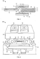
- Figure 2 shows in perspective view a heating apparatus 20 according to the invention.
- Heating apparatus 20 is intended for heating infrared-initiated splice seals in a production environment involving a heavy duty cycle in which large numbers of the splice seals are serially heated in order to complete them.
- the apparatus 20 comprises a heating area 21 defined by a pair of structural components 22, 23 in the form of a pair of rigid, metallic shells that are hingeably supported in a framework.
- the shells 22, 23 are such that they can be moved towards and away from one another on the hinges so as to close and open the heating area 21.
- the shells 22, 23 as shown each comprise a plurality of walls that between them define a hollow interior when the shells 22, 23 are moved together so that the edges of their walls are in abutting relationship.
- Each shell 22, 23 comprises a pair of end walls of which two, 26, 27 are visible in Figure 2.
- Each end wall 26, 27 has formed therein a semi-circular cut-out 28 in which a partly-completed splice, in the form shown schematically in Figure 1, may be positioned to undergo heating in the apparatus 20.
- a partly-completed splice in the form shown schematically in Figure 1
- the wires of the splice are located in the semi-circular cut-outs 28 in a manner known in the art.
- outermost walls 37, 38 are upstanding at the ends of lower shell 23.
- the outermost walls 37, 38 provide structural support for the apparatus 20 and also form part of a safety / insulation guard intended to protect operators of the apparatus 20.
- the outermost walls 37, 38 include recessed portions 39, 41 that when the shells 22, 23 are closed are essentially in register with the cut-outs 28.
- the arrangement is such that when the shells 22, 23 are open a series of preassembled splices requiring sealing may be inserted into the heating area 21 seriatim on respective, moveable splice supports (not shown) which may be eg. carriages.
- respective, moveable splice supports (not shown) which may be eg. carriages.
- Respective support / connector brackets 29 are supported within shells 22 and 23 extending along the length of elongate heating area 21 on the interior thereof.
- Each support / connector bracket 29 includes operatively supported therein a lamp bulb 31 that is oriented to direct infrared heat energy from the outer part of the heating area 21 towards the centre axis thereof, along which a splice seal 10 is lain during heating operations.
- each support / connector bracket includes at either end a connector clamp 32 for connecting each bulb 31 to a source of electrical power; and supporting each bulb 31.
- the heating area incorporates reflector panels 33 lying between each bulb 31 and the exterior walls of the shells 22, 23 such that the reflector panels 33 intensify the radiant heat energy that is directed towards splice seal supported in apparatus 20 during operation thereof.
- the apparatus 20 may include up to six sources of infrared heat energy in the form of lamps 31 located as desired (in accordance with the chosen arrangement) in the heating area 21. Different numbers of sources however may be employed in other embodiments within the scope of the invention.
- the exterior walls of the shells 22, 23 are perforated and support respective pairs blower devices in the form of air fans 34. These are arranged so as in use of the apparatus 20 to blow air from the exterior of the heating area 21 into the interior thereof and over the various structural components constituted by the walls of the shells 22, 23, the cut-outs 28, the bulbs 31, the support / connector brackets 29 and the reflectors 33. As explained in relation to the examples below, such an arrangement advantageously by convection (in the case of the fans shown) reduces the temperature of the various components whilst not inhibiting the coupling of infrared energy by radiation from the lamp bulbs 31 to the inner layers 18 of the cylindrical sleeves 16 of the splice seals 10 inserted into the apparatus.
- the lamps 31 and the fans 34 may be switched off while the shells are separated during removal of the completed splice and insertion into the heating area 21 of the next splice requiring completion.
- the fans may be operated continuously
- FIG 3 shows a variation on part of the Figure 1 apparatus, in which the fans need not be present and from which in practice the fans would be absent.
- the fans 34 are dispensed with.
- the cooling device is in the form of a heat exchanger. This in turn is embodied as a copper pipe 36 that is secured in heat-transferring (conducting) contact with the walls of the shell 22.
- a cooling fluid such as chilled water
- the copper pipe 36 would extend over the entire inner surface of the shell 22.
- a similar copper pipe 36 would also be present, in conducting contact with the inner side of the other shell 23.
- an RBK-ILS Mk2 processor was modified to include six 400W quartz halogen lamps which, when powered in series at 85V and 15A, had a wavelength of approximately 1.3 microns. These were switched on only during the product heating cycle. Within each half-shell containing three lamps was fitted an aluminium reflector to focus the radiation towards the product (splice). Between the reflector and the rear support frame was fitted a piped, water cooled heat sink with good thermal contact to the adjacent shell. Cold water was pumped through at 1 litre per minute.
- the water-cooled heat sink was replaced by 2 cooling fans on each half-shell which in used force air over and around aluminium reflective shields and other oven components.
- Each cooling fan had an air flow of 25m 3 per hour.
- An RBK-ILS Mk2 processor was modified to include six 400W quartz halogen lamps which, when powered in series at 85V and 15A, had a wavelength of approx. 1.3 microns. These were switched on only during the product heating cycle. Behind each half-shell containing three lamps was fitted an aluminised reflector to focus the radiation towards the product. Between the reflector and the rear support frame was fitted a piped, water cooled heat sink. Cold water was pumped through at 1 litre per minute. The temperature of the reflector was monitored during a very high duty cycle of 30 installations with an installation time of 6 seconds and 6 seconds between installations. Without cooling the temperature reached an average of 270C after 2 cycles. With cooling the temperature reached an average of 110C.
- the invention provides an effective, practical and low-cost arrangement that dramatically improves the performance of heating apparatuses for infrared-initiated splice seals.
Landscapes
- Physics & Mathematics (AREA)
- Optics & Photonics (AREA)
- Health & Medical Sciences (AREA)
- Electromagnetism (AREA)
- Toxicology (AREA)
- Engineering & Computer Science (AREA)
- Mechanical Engineering (AREA)
- Lining Or Joining Of Plastics Or The Like (AREA)
- Manufacturing Of Electrical Connectors (AREA)
- Insulating Bodies (AREA)
- Processing Of Terminals (AREA)
Applications Claiming Priority (1)
| Application Number | Priority Date | Filing Date | Title |
|---|---|---|---|
| GB0603293A GB2435233A (en) | 2006-02-18 | 2006-02-18 | Infrared splicing |
Publications (2)
| Publication Number | Publication Date |
|---|---|
| EP1821374A2 true EP1821374A2 (de) | 2007-08-22 |
| EP1821374A3 EP1821374A3 (de) | 2008-08-13 |
Family
ID=36142083
Family Applications (1)
| Application Number | Title | Priority Date | Filing Date |
|---|---|---|---|
| EP07250660A Pending EP1821374A3 (de) | 2006-02-18 | 2007-02-16 | Vorrichtung und Verfahren zum Erhitzen einer infrarotaktivierten Nahtabdichtung |
Country Status (5)
| Country | Link |
|---|---|
| US (1) | US7565067B2 (de) |
| EP (1) | EP1821374A3 (de) |
| JP (1) | JP2007220681A (de) |
| CN (1) | CN101026908A (de) |
| GB (1) | GB2435233A (de) |
Cited By (2)
| Publication number | Priority date | Publication date | Assignee | Title |
|---|---|---|---|---|
| US8636864B2 (en) | 2007-09-20 | 2014-01-28 | Tyco Electronics Uk Ltd. | Article and method for forming a wire seal |
| DE102017104865B3 (de) | 2017-03-08 | 2018-03-22 | Lisa Dräxlmaier GmbH | Vorrichtung und verfahren zum automatisierten abdichten einer verbindungsstelle von miteinander verschweissten elektrischen leitungen |
Families Citing this family (12)
| Publication number | Priority date | Publication date | Assignee | Title |
|---|---|---|---|---|
| ES2350212B1 (es) * | 2008-12-19 | 2011-11-11 | Bsh Electrodomesticos España, S.A. | Radiador para un aparato domestico. |
| JP5605295B2 (ja) * | 2011-04-19 | 2014-10-15 | 日立金属株式会社 | 加熱収縮装置及び封止加工方法 |
| DE102012025299A1 (de) * | 2012-12-28 | 2014-07-03 | Helmut Haimerl | Heizstrahler mit Heizrohrelement |
| FR3008019B1 (fr) * | 2013-07-04 | 2015-07-17 | Sidel Participations | Module de chauffage comportant une lampe et une lentille fixee par une bride sur une partie non emissive de la lampe |
| CN105610030B (zh) * | 2016-03-12 | 2017-12-01 | 慈溪市宏晟机械设备有限公司 | 一种自动双头压着双穿热缩管机 |
| CN105720456B (zh) * | 2016-04-20 | 2018-07-31 | 泉州永春佳鼎农业机械有限公司 | 插排线扎线机的软化装置 |
| DE102017011354A1 (de) * | 2017-12-07 | 2019-06-13 | Kocher-Plastik Maschinenbau Gmbh | Verfahren und Vorrichtung zum Verbinden von mindestens zwei Kunststoffteilen |
| CN108790189B (zh) * | 2018-06-27 | 2019-11-26 | 重庆工商大学 | 一种红外热铆机 |
| FR3088577A1 (fr) * | 2018-11-16 | 2020-05-22 | Saint-Gobain Glass France | Procede de fabrication d'un vitrage feuillete dont une face au moins de l'empilement des constituants est exposee a un rayonnement de spectre choisi dans deux domaines etroits definis |
| KR102050227B1 (ko) * | 2019-03-06 | 2020-01-08 | 허수범 | 실리콘케이블 제조장치 |
| CN110244504B (zh) * | 2019-06-17 | 2021-02-26 | 宁波市法诺工业产品设计有限公司 | 一种多功能教育投影仪装置 |
| CN112382905B (zh) * | 2020-09-10 | 2022-04-08 | 安徽蓝润自动化仪表有限公司 | 一种多芯电缆用快速接线装置及操作方法 |
Citations (1)
| Publication number | Priority date | Publication date | Assignee | Title |
|---|---|---|---|---|
| JPH05122817A (ja) | 1991-10-29 | 1993-05-18 | Showa Electric Wire & Cable Co Ltd | ケーブル接続部の形成方法 |
Family Cites Families (11)
| Publication number | Priority date | Publication date | Assignee | Title |
|---|---|---|---|---|
| US4085286A (en) * | 1974-09-27 | 1978-04-18 | Raychem Corporation | Heat-recoverable sealing article with self-contained heating means and method of sealing a splice therewith |
| US4419304A (en) | 1980-07-15 | 1983-12-06 | Western Electric Company, Inc. | Method for forming seals with heat shrinkable materials |
| US4528150A (en) * | 1982-09-23 | 1985-07-09 | Northern Telecom Limited | Methods and apparatus for sealing articles |
| US4719332A (en) * | 1986-05-05 | 1988-01-12 | Strategic Products, Inc. | Tube shrinking oven |
| US4749843A (en) * | 1986-10-14 | 1988-06-07 | Research, Inc. | Enveloping radiant heater |
| US5060289A (en) * | 1990-05-04 | 1991-10-22 | Research, Incorporated | Portable tube shrinking tool |
| JPH066925A (ja) | 1992-06-18 | 1994-01-14 | Showa Electric Wire & Cable Co Ltd | ケーブル接続部の形成方法 |
| US5740314A (en) * | 1995-08-25 | 1998-04-14 | Edison Welding Institute | IR heating lamp array with reflectors modified by removal of segments thereof |
| JPH10214669A (ja) | 1997-01-30 | 1998-08-11 | Fujikura Ltd | 電力ケーブル接続部の加熱方法 |
| JPH1118239A (ja) | 1997-06-23 | 1999-01-22 | Sumitomo Electric Ind Ltd | 熱収縮チューブ用収縮工具および収縮方法 |
| US6529686B2 (en) * | 2001-06-06 | 2003-03-04 | Fsi International, Inc. | Heating member for combination heating and chilling apparatus, and methods |
-
2006
- 2006-02-18 GB GB0603293A patent/GB2435233A/en not_active Withdrawn
-
2007
- 2007-02-13 US US11/674,209 patent/US7565067B2/en active Active
- 2007-02-16 EP EP07250660A patent/EP1821374A3/de active Pending
- 2007-02-16 JP JP2007036369A patent/JP2007220681A/ja active Pending
- 2007-02-17 CN CNA2007100849583A patent/CN101026908A/zh active Pending
Patent Citations (1)
| Publication number | Priority date | Publication date | Assignee | Title |
|---|---|---|---|---|
| JPH05122817A (ja) | 1991-10-29 | 1993-05-18 | Showa Electric Wire & Cable Co Ltd | ケーブル接続部の形成方法 |
Cited By (2)
| Publication number | Priority date | Publication date | Assignee | Title |
|---|---|---|---|---|
| US8636864B2 (en) | 2007-09-20 | 2014-01-28 | Tyco Electronics Uk Ltd. | Article and method for forming a wire seal |
| DE102017104865B3 (de) | 2017-03-08 | 2018-03-22 | Lisa Dräxlmaier GmbH | Vorrichtung und verfahren zum automatisierten abdichten einer verbindungsstelle von miteinander verschweissten elektrischen leitungen |
Also Published As
| Publication number | Publication date |
|---|---|
| GB2435233A (en) | 2007-08-22 |
| CN101026908A (zh) | 2007-08-29 |
| US20070196082A1 (en) | 2007-08-23 |
| JP2007220681A (ja) | 2007-08-30 |
| GB0603293D0 (en) | 2006-03-29 |
| EP1821374A3 (de) | 2008-08-13 |
| US7565067B2 (en) | 2009-07-21 |
Similar Documents
| Publication | Publication Date | Title |
|---|---|---|
| EP1821374A2 (de) | Vorrichtung und Verfahren zum Erhitzen einer infrarotaktivierten Nahtabdichtung | |
| CA1069192A (en) | Heat recoverable self-heating sealing article and method of sealing a splice therefrom | |
| US4095044A (en) | Multiple cable adapter and splice case including the same | |
| US6359226B1 (en) | Device and method for protecting and sealing exposed wires | |
| US20120080419A1 (en) | Clip-on Heater | |
| US4419304A (en) | Method for forming seals with heat shrinkable materials | |
| JPS58194267A (ja) | クリツプ | |
| CA2133101A1 (en) | Method and apparatus for forming an electrical connection | |
| US3515853A (en) | Heating apparatus | |
| EP0304333B1 (de) | Heizvorrichtung | |
| US6402856B1 (en) | Method and apparatus for stripping an optical fiber | |
| JP2019509010A5 (de) | ||
| US20200114568A1 (en) | Device and Methods for Armoring Heat Shrink Kits for Impact and Flammability Protection | |
| EP2092611B1 (de) | Drahtversiegelungsprodukt und -verfahren | |
| EP0307200B1 (de) | Wärmerückstellbarer Artikel | |
| EP0433368B1 (de) | Verfahren zum abdichten eines kabels | |
| AU2022200785B2 (en) | Method of installing a heat shrink cover, electrical heating system, and installation system | |
| EP0307198A2 (de) | Leitfähiger Kunststoffartikel | |
| JPH0516234A (ja) | 熱収縮チユーブの製造方法 | |
| KR200304481Y1 (ko) | 파이프용 연결장치 | |
| JP2005268194A (ja) | 電線接続部を密封した電気部品、及びその製造方法 | |
| WO1993019925A1 (en) | Environmental protection | |
| JPH11505362A (ja) | 導体のケーブルまたは束をブロックする方法 | |
| JPH06140131A (ja) | 面状発熱体及びその製造方法 | |
| JPH0845574A (ja) | スプライス部モールド装置 |
Legal Events
| Date | Code | Title | Description |
|---|---|---|---|
| PUAI | Public reference made under article 153(3) epc to a published international application that has entered the european phase |
Free format text: ORIGINAL CODE: 0009012 |
|
| AK | Designated contracting states |
Kind code of ref document: A2 Designated state(s): AT BE BG CH CY CZ DE DK EE ES FI FR GB GR HU IE IS IT LI LT LU LV MC NL PL PT RO SE SI SK TR |
|
| AX | Request for extension of the european patent |
Extension state: AL BA HR MK YU |
|
| PUAL | Search report despatched |
Free format text: ORIGINAL CODE: 0009013 |
|
| AK | Designated contracting states |
Kind code of ref document: A3 Designated state(s): AT BE BG CH CY CZ DE DK EE ES FI FR GB GR HU IE IS IT LI LT LU LV MC NL PL PT RO SE SI SK TR |
|
| AX | Request for extension of the european patent |
Extension state: AL BA HR MK RS |
|
| 17P | Request for examination filed |
Effective date: 20081114 |
|
| 17Q | First examination report despatched |
Effective date: 20081229 |
|
| STAA | Information on the status of an ep patent application or granted ep patent |
Free format text: STATUS: EXAMINATION IS IN PROGRESS |
|
| AKX | Designation fees paid |
Designated state(s): AT BE BG CH CY CZ DE DK EE ES FI FR GB GR HU IE IS IT LI LT LU LV MC NL PL PT RO SE SI SK TR |