EP1821393A2 - Hochleistungsgenerator mit verstärkter Statorwärmeabfuhr - Google Patents
Hochleistungsgenerator mit verstärkter Statorwärmeabfuhr Download PDFInfo
- Publication number
- EP1821393A2 EP1821393A2 EP07102744A EP07102744A EP1821393A2 EP 1821393 A2 EP1821393 A2 EP 1821393A2 EP 07102744 A EP07102744 A EP 07102744A EP 07102744 A EP07102744 A EP 07102744A EP 1821393 A2 EP1821393 A2 EP 1821393A2
- Authority
- EP
- European Patent Office
- Prior art keywords
- stator
- diameter
- generator
- rotor
- main
- Prior art date
- Legal status (The legal status is an assumption and is not a legal conclusion. Google has not performed a legal analysis and makes no representation as to the accuracy of the status listed.)
- Pending
Links
- 238000001816 cooling Methods 0.000 claims abstract description 44
- 239000012530 fluid Substances 0.000 claims abstract description 18
- 239000002826 coolant Substances 0.000 claims abstract description 15
- 238000004891 communication Methods 0.000 claims abstract description 8
- 238000004804 winding Methods 0.000 claims description 27
- 238000003475 lamination Methods 0.000 claims description 20
- 239000000463 material Substances 0.000 description 9
- 239000012809 cooling fluid Substances 0.000 description 7
- XEEYBQQBJWHFJM-UHFFFAOYSA-N Iron Chemical compound [Fe] XEEYBQQBJWHFJM-UHFFFAOYSA-N 0.000 description 4
- 230000000712 assembly Effects 0.000 description 3
- 238000000429 assembly Methods 0.000 description 3
- 230000004323 axial length Effects 0.000 description 3
- 238000010586 diagram Methods 0.000 description 2
- 229910052742 iron Inorganic materials 0.000 description 2
- 239000000314 lubricant Substances 0.000 description 2
- 239000007921 spray Substances 0.000 description 2
- 229910052720 vanadium Inorganic materials 0.000 description 2
- LEONUFNNVUYDNQ-UHFFFAOYSA-N vanadium atom Chemical compound [V] LEONUFNNVUYDNQ-UHFFFAOYSA-N 0.000 description 2
- 230000002411 adverse Effects 0.000 description 1
- 239000000956 alloy Substances 0.000 description 1
- 230000001627 detrimental effect Effects 0.000 description 1
- -1 for example Substances 0.000 description 1
- 230000003116 impacting effect Effects 0.000 description 1
- XWHPIFXRKKHEKR-UHFFFAOYSA-N iron silicon Chemical compound [Si].[Fe] XWHPIFXRKKHEKR-UHFFFAOYSA-N 0.000 description 1
- 229910001004 magnetic alloy Inorganic materials 0.000 description 1
- 238000012986 modification Methods 0.000 description 1
- 230000004048 modification Effects 0.000 description 1
- 238000012806 monitoring device Methods 0.000 description 1
- 238000012544 monitoring process Methods 0.000 description 1
- 239000003921 oil Substances 0.000 description 1
- 238000010248 power generation Methods 0.000 description 1
- 238000005507 spraying Methods 0.000 description 1
- 238000012546 transfer Methods 0.000 description 1
Images

Classifications
-
- H—ELECTRICITY
- H02—GENERATION; CONVERSION OR DISTRIBUTION OF ELECTRIC POWER
- H02K—DYNAMO-ELECTRIC MACHINES
- H02K9/00—Arrangements for cooling or ventilating
- H02K9/19—Arrangements for cooling or ventilating for machines with closed casing and closed-circuit cooling using a liquid cooling medium, e.g. oil
-
- H—ELECTRICITY
- H02—GENERATION; CONVERSION OR DISTRIBUTION OF ELECTRIC POWER
- H02K—DYNAMO-ELECTRIC MACHINES
- H02K1/00—Details of the magnetic circuit
- H02K1/06—Details of the magnetic circuit characterised by the shape, form or construction
- H02K1/12—Stationary parts of the magnetic circuit
- H02K1/20—Stationary parts of the magnetic circuit with channels or ducts for flow of cooling medium
-
- H—ELECTRICITY
- H02—GENERATION; CONVERSION OR DISTRIBUTION OF ELECTRIC POWER
- H02K—DYNAMO-ELECTRIC MACHINES
- H02K5/00—Casings; Enclosures; Supports
- H02K5/04—Casings or enclosures characterised by the shape, form or construction thereof
- H02K5/20—Casings or enclosures characterised by the shape, form or construction thereof with channels or ducts for flow of cooling medium
- H02K5/203—Casings or enclosures characterised by the shape, form or construction thereof with channels or ducts for flow of cooling medium specially adapted for liquids, e.g. cooling jackets
Definitions
- the present invention relates to relatively high power generators and, more particularly, to high power generators that are used with gas turbine engines such as those used in aircraft, tanks, ships, terrestrial vehicles, or other applications.
- AC generator systems to supply relatively constant frequency AC power.
- Many of the AC generator systems installed in these vehicles include three separate brushless generators, namely, a permanent magnet generator (PMG), an exciter, and a main generator.
- the PMG includes a rotor having permanent magnets mounted thereon, and a stator having a plurality of windings. When the PMG rotor rotates, the permanent magnets induce AC currents in PMG stator windings. These AC currents are typically fed to a regulator or a control device, which in turn outputs a DC current to the exciter.
- the exciter typically includes single-phase (e.g., DC) stator windings and multi-phase (e.g., three-phase) rotor windings.
- the DC current from the regulator or control device is supplied to exciter stator windings, and as the exciter rotor rotates, three phases of AC current are typically induced in the rotor windings.
- Rectifier circuits that rotate with the exciter rotor rectify this three-phase AC current, and the resulting DC currents are provided to the main generator.
- the main generator additionally includes a rotor and a stator having single-phase (e.g., DC) and multi-phase (e.g., three-phase) windings, respectively.
- the DC currents from the rectifier circuits are supplied to the rotor windings.
- three phases of AC current are induced in main generator stator windings.
- This three-phase AC current can then be provided to a load such as, for example, electrical aircraft systems.
- some of the electrical components within the generator may generate heat due to electrical losses, and may thus be supplied with a cooling medium.
- the main rotor windings and main stator windings are cooled using a cooling medium, such as a lubricant, that flows in and through the generator.
- the main rotor and main stator windings are cooled by spraying the cooling medium, via orifices in the main rotor shaft, onto end turns of the main rotor and main stator windings.
- the cooling medium flow through the main rotor shaft also provides conduction cooling of the main rotor along its axial length. Conduction cooling along the axial length of the main stator is provided via a stator back iron cooling flow path. More specifically, a portion of the cooling medium is directed through a flow path formed in or on the stator back iron.
- the cooling scheme can present certain drawbacks.
- the cooling scheme can result in insufficient cooling of the main stator near its axially positioned center, causing a relatively high temperature hot spot at or near this location, which can be detrimental to the stator windings.
- the present invention provides a high speed, high power generator that provides enhanced cooling of the main stator near its axially positioned center.
- a high power generator includes a generator housing, a main rotor, and a main stator.
- the generator housing has a main stator cooling flow passage formed therein that is configured to receive a flow of a cooling medium.
- the main rotor is rotationally mounted in the generator housing.
- the main stator is mounted within the generator housing and surrounds at least a portion of the main rotor.
- the main stator includes a stator core coupled to the generator housing adjacent the main stator cooling flow passage, and includes two or more nominal-diameter sections and one or more reduced-diameter sections.
- the nominal-diameter sections each have a first outer diameter
- the reduced-diameter sections each have a second outer diameter that is less than the first diameter.
- Each reduced-diameter section is disposed between two nominal-diameter sections and is in fluid communication with the stator cooling flow passage.
- a stator assembly for a high power generator includes a plurality of stator windings, and a stator core adapted to be coupled to a generator housing and having the plurality of stator windings wound thereon.
- the stator core includes two or more nominal-diameter sections and one or more reduced-diameter sections.
- the nominal-diameter sections each have a first outer diameter
- the reduced-diameter sections each have a second outer diameter that is less than the first diameter.
- Each reduced-diameter section is disposed between two nominal-diameter sections and is in fluid communication with the stator cooling flow passage.
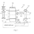
- FIG. 1 is a functional schematic diagram of an exemplary high speed generator embodiment
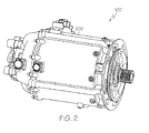
- FIG. 2 is a perspective view of a physical embodiment of the generator shown in FIG. 1;
- FIG. 3 is a simplified schematic cross section view of the exemplary generator shown in FIGS. 1 and 2 according to an embodiment of the present invention.
- FIG. 1 a functional schematic block diagram of an exemplary high speed generator system 100 for use with a gas turbine engine such as that in an aircraft is depicted.
- This exemplary generator system 100 which is commonly known as a brushless AC generator, includes a permanent magnet generator (PMG) 110, an exciter 120, a main generator 130, a generator control unit 140, and one or more rectifier assemblies 150.
- PMG permanent magnet generator
- a rotor 112 of the PMG 110, a rotor 124 of the exciter 120, and a rotor 132 of the main generator 130 all rotate.
- the rotational speed of these components may vary.
- the rotational speed may be, for example, in the range of about 12,000 to about 24,000 r.p.m., or greater.
- the PMG rotor 112 rotates, the PMG 110 generates and supplies, via a PMG stator 114, AC power to the generator control unit 140.
- the generator control unit 140 supplies direct current (DC) power to a stator 122 of the exciter 120.
- the exciter rotor 124 in turn supplies AC power to the rectifier assemblies 150.
- the output from the rectifier assemblies 150 is DC power and is supplied to the main rotor 132, which in turn outputs AC power from a main stator 134.
- the generator system 100 is capable of providing output power at a variety of frequencies and over a variety of frequency ranges. Further, typically the output power from the main generator stator 134 is three-phase AC power.
- the generator control unit 140 can regulate the power output based upon monitoring signals provided to it from monitoring devices 195.
- the PMG rotor 112, the exciter rotor 124, and the main rotor 132 are all mounted on a common shaft 136, and thus all rotate along a single axis 198 at the same rotational speed. It will be appreciated, however, that this is merely exemplary of a particular preferred embodiment. It will additionally be appreciated that the generator system 100, or at least portions of the system 100, may be housed within a generator housing 202, a perpsective view of which is illustrated in FIG. 2.
- FIG. 3 is a simplified cross section side view representative of the schematic and physical high power generators described above, it is seen that the shaft 136 includes an inner surface 302 that defines an internal fluid flow passage 304, and an outer surface 306.
- the shaft 136 receives a supply of cooling fluid such as, for example, oil or other lubricant, via an opening 308 in a first end 312 thereof.
- the supplied cooling fluid flows through the opening 308 and into and through the internal fluid flow passage 304 toward a closed second end 314 of the shaft 136.
- the shaft 136 additionally includes a plurality of end turn cooling supply orifices 316.
- the end turn cooling supply orifices each extend between the shaft inner 302 and outer 306 surfaces, and are thus in fluid communication with the internal fluid flow passage 304.
- the end turn cooling supply orifices 316 are disposed on the shaft 136 near both ends of the main rotor 132.
- the end turn cooling supply orifices 216 may be provided near only one end of the main rotor 132.
- the main rotor 132 is mounted on the shaft 136, and includes a plurality of poles 318, and a plurality of coils 322 (for clarity, only one shown).
- the poles 318 extend radially away from the shaft 136 and, as is generally known, are preferably spaced evenly apart from one another.
- the poles 318 are formed of a plurality of laminations 324, which are shrunk fit onto the shaft 136.
- the rotor laminations 324 as is generally known, are continuous stacks of a magnetically permeable material. The particular material may be any one of numerous magnetically permeable materials.
- the laminations 324 are formed of a magnetic alloy material such as, for example, vanadium permendur. It will be appreciated that this material is only exemplary, and that other suitable materials can be used for the main rotor laminations 324.
- each rotor coil 322 is wrapped, one each, around a pole 318, and are preferably formed by wrapping numerous individual wire windings around one of the poles 318.
- each rotor coil 322 includes two end turns 326 (e.g., 326-1, 326-2), each of which is made up of wire segments that loop around ends of the pole 318.
- cooling fluid supplied to the shaft inner fluid flow passage 304 is directed, via centrifugal force, through the end turn cooling supply orifices 316, and is sprayed onto, among other things, the rotor coil end turns 326.
- This cooling fluid spray provides cooling to the rotor coil end turns 326 and, as will be described further below, to portions of the main stator 134. It will be appreciated that the cooling fluid flowing through the shaft internal fluid flow passage 304 also provides conduction cooling for the main rotor laminations 324.
- the main stator 134 is also mounted within the generator housing 202, and is preferably positioned such that it surrounds the main rotor 132.
- the main stator 134 includes a stator core 328 and a plurality of stator coils 332, and is coupled to the generator housing 202. More specifically, the main stator 134 is preferably coupled to the generator housing 202 adjacent to a stator cooling flow passage 336 that is formed in the housing 202.
- the stator cooling flow passage 336 is configured to receive a flow of the cooling medium, which is used to conduction cool the main stator 134.
- the stator cooling flow passage 336 is implemented as a spirally configured cavity. It will be appreciated, however, that this is merely exemplary of any one of numerous configurations.
- the stator core 328 is configured such that one or more portions thereof have a reduced diameter.
- the stator core 328 at least in the depicted embodiment, includes two nominal-diameter sections 338 and one reduced-diameter section 342.
- the nominal-diameter sections 338 each have a first outer diameter (D1), and are coupled the generator housing 202.
- the reduced-diameter section 342 has a second outer diameter (D2) that is less than the first outer diameter, and is disposed between the nominal-diameter sections 338.
- the reduced-diameter section 342 forms a cavity 345 between the stator core 328 and the generator housing 202 that is in fluid communication with the stator cooling flow passage 336.
- stator cooling flow passage 336 when cooling medium is supplied to the stator cooling flow passage 336, the cooling medium additionally flows through the cavity 345, preferably in contact with the reduced-diameter section 342.
- the stator core 328 could be implemented with more than one reduced-diameter section 342.
- each is preferably disposed between two nominal-diameter sections 338.
- the main stator core 328 is preferably formed of a plurality of laminations 344.
- the main stator core laminations 344 are stacks of a magnetically permeable material, which may be any one of numerous magnetically permeable materials such as, for example, silicon iron, or vanadium permendur.
- the main stator core laminations 344 are not all substantially identical.
- main stator core nominal-diameter sections 338 are formed of a stack of nominal-diameter laminations, each having the nominal diameter
- main stator core reduced-diameter section(s) 342 are formed of a stack of reduced-diameter laminations, each having the reduced diameter.
- the stator coils 332 are wrapped around the stator core 328, preferably within non-illustrated slots formed in the stator core 328, and similar to the rotor coils 322 includes a pair of end turns 334 (e.g., 334-1, 334-2). A portion of the cooling fluid spray that is directed onto the rotor coil end turns 326 is also directed onto the stator coil end turns 334, and provides cooling thereto. It will be appreciated that the stator core 328 is additionally cooled via cooling fluid that flows through the stator cooling flow passage 336.
- the high speed, high power generator described herein provides enhanced cooling of the main stator, most notably near its axially positioned center. As such, the axial length of the generator can be increased, if needed to meet increase power generation demands, without adversely impacting thermal management of the generator.
Landscapes
- Engineering & Computer Science (AREA)
- Power Engineering (AREA)
- Motor Or Generator Cooling System (AREA)
- Iron Core Of Rotating Electric Machines (AREA)
Applications Claiming Priority (1)
| Application Number | Priority Date | Filing Date | Title |
|---|---|---|---|
| US11/359,116 US7439646B2 (en) | 2006-02-21 | 2006-02-21 | High power generator with enhanced stator heat removal |
Publications (2)
| Publication Number | Publication Date |
|---|---|
| EP1821393A2 true EP1821393A2 (de) | 2007-08-22 |
| EP1821393A3 EP1821393A3 (de) | 2009-01-21 |
Family
ID=37909429
Family Applications (1)
| Application Number | Title | Priority Date | Filing Date |
|---|---|---|---|
| EP07102744A Pending EP1821393A3 (de) | 2006-02-21 | 2007-02-20 | Hochleistungsgenerator mit verstärkter Statorwärmeabfuhr |
Country Status (2)
| Country | Link |
|---|---|
| US (1) | US7439646B2 (de) |
| EP (1) | EP1821393A3 (de) |
Families Citing this family (9)
| Publication number | Priority date | Publication date | Assignee | Title |
|---|---|---|---|---|
| US8450888B2 (en) * | 2009-04-20 | 2013-05-28 | General Electric Company | Integrated brushless starter/generator system |
| US8143759B2 (en) * | 2009-04-30 | 2012-03-27 | Hamilton Sundstrand Corporation | Laminated stator assembly |
| US9154006B2 (en) * | 2010-03-24 | 2015-10-06 | Aisin Aw Co., Ltd. | Rotor for rotating electric machine |
| US20160294231A1 (en) | 2015-04-02 | 2016-10-06 | Hamilton Sundstrand Corporation | Stator heat transfer feature |
| TWI673944B (zh) | 2017-03-24 | 2019-10-01 | 美商江森自控技術公司 | 用於冷卻器馬達的液體噴射噴嘴 |
| US10560002B2 (en) * | 2017-03-29 | 2020-02-11 | Ford Global Technologies, Llc | Coolant flow distribution using coating materials |
| US11022004B2 (en) * | 2017-03-31 | 2021-06-01 | The Boeing Company | Engine shaft integrated motor |
| CN108471217A (zh) * | 2018-07-06 | 2018-08-31 | 李天举 | 磁动力发电机组 |
| CN112152361A (zh) * | 2020-10-19 | 2020-12-29 | 珠海格力电器股份有限公司 | 一种转子结构、永磁电机以及冷却方法 |
Citations (4)
| Publication number | Priority date | Publication date | Assignee | Title |
|---|---|---|---|---|
| JPH08103053A (ja) | 1994-09-30 | 1996-04-16 | Suzuki Motor Corp | モータの冷却装置 |
| JPH1141861A (ja) | 1997-07-22 | 1999-02-12 | Denso Corp | 回転電機 |
| DE10019914A1 (de) | 1999-04-30 | 2001-02-01 | Valeo Equip Electr Moteur | Durch ein internes Kühlmittel gekühlter Wechselstromgenerator für Kraftfahrzeuge |
| US20040066098A1 (en) | 2002-10-04 | 2004-04-08 | Doherty Kieran P.J. | High speed generator with the main rotor housed inside the shaft |
Family Cites Families (19)
| Publication number | Priority date | Publication date | Assignee | Title |
|---|---|---|---|---|
| US1578509A (en) * | 1923-07-20 | 1926-03-30 | Westinghouse Electric & Mfg Co | Fluid-pressure control of turbo ventilation |
| US1594058A (en) * | 1924-10-24 | 1926-07-27 | Gen Electric | Dynamo-electric machine |
| US1761587A (en) * | 1928-11-19 | 1930-06-03 | Allis Chalmers Mfg Co | Dynamo-electric machine |
| US2285960A (en) * | 1940-08-02 | 1942-06-09 | Carl J Fechheimer | Dynamoelectric machine |
| US3009072A (en) * | 1958-01-28 | 1961-11-14 | Scott L & Electromotors Ltd | Fluid cooled motors |
| US3805547A (en) * | 1972-11-21 | 1974-04-23 | Trane Co | Refrigeration machine with liquid refrigerant cooled motor |
| FR2223859B1 (de) * | 1973-03-29 | 1976-06-25 | Siemens Ag | |
| DE2449090A1 (de) * | 1973-10-17 | 1975-04-30 | Hitachi Ltd | Stator einer rotierenden elektrischen maschine |
| DE3134080A1 (de) * | 1981-08-28 | 1983-04-14 | Robert Bosch Gmbh, 7000 Stuttgart | Elektrische maschine, insbesondere drehstromgenerator, mit innenliegenden kuehlkanaelen |
| US4514652A (en) * | 1983-07-13 | 1985-04-30 | Sundstrand Corporation | Liquid cooled high speed synchronous machine |
| US5502368A (en) * | 1994-06-06 | 1996-03-26 | Ecoair Corp. | Hybrid alternator with voltage regulator |
| US5682074A (en) * | 1994-03-02 | 1997-10-28 | Northrop Grumman Corporation | Electric vehicle motor |
| DE19645272A1 (de) * | 1996-11-02 | 1998-05-07 | Asea Brown Boveri | Gasgekühlte elektrische Maschine |
| US6091168A (en) * | 1998-12-22 | 2000-07-18 | Hamilton Sundstrand Corporation | Rotor for a dynamoelectric machine |
| JP2000308311A (ja) * | 1999-04-14 | 2000-11-02 | Hitachi Ltd | 回転電機 |
| JP3806303B2 (ja) * | 2000-12-11 | 2006-08-09 | 三菱重工業株式会社 | 発電機における冷却構造 |
| GB2378046A (en) * | 2001-07-18 | 2003-01-29 | Turbo Genset Company Ltd | Cooling flow in discoid stator windings |
| US6943469B2 (en) * | 2002-11-01 | 2005-09-13 | Siemens Westinghouse Power Corporation | Supplemented zonal ventilation system for electric generator |
| DE10344630A1 (de) * | 2003-09-25 | 2005-05-04 | Bosch Gmbh Robert | Fluidgekühlte elektrische Maschine und Verfahren zur Herstellung einer solchen |
-
2006
- 2006-02-21 US US11/359,116 patent/US7439646B2/en not_active Expired - Fee Related
-
2007
- 2007-02-20 EP EP07102744A patent/EP1821393A3/de active Pending
Patent Citations (4)
| Publication number | Priority date | Publication date | Assignee | Title |
|---|---|---|---|---|
| JPH08103053A (ja) | 1994-09-30 | 1996-04-16 | Suzuki Motor Corp | モータの冷却装置 |
| JPH1141861A (ja) | 1997-07-22 | 1999-02-12 | Denso Corp | 回転電機 |
| DE10019914A1 (de) | 1999-04-30 | 2001-02-01 | Valeo Equip Electr Moteur | Durch ein internes Kühlmittel gekühlter Wechselstromgenerator für Kraftfahrzeuge |
| US20040066098A1 (en) | 2002-10-04 | 2004-04-08 | Doherty Kieran P.J. | High speed generator with the main rotor housed inside the shaft |
Also Published As
| Publication number | Publication date |
|---|---|
| US7439646B2 (en) | 2008-10-21 |
| EP1821393A3 (de) | 2009-01-21 |
| US20070194639A1 (en) | 2007-08-23 |
Similar Documents
| Publication | Publication Date | Title |
|---|---|---|
| EP1821392A2 (de) | Hochleistungsgenerator mit verstärkter Wärmeabfuhr | |
| EP1821393A2 (de) | Hochleistungsgenerator mit verstärkter Statorwärmeabfuhr | |
| US7786630B2 (en) | Spray cooled V-wedge for aerospace generator | |
| US8922086B2 (en) | Electric machine having a hybrid-excited rotor | |
| US11569703B2 (en) | Integrated wedge cooling distribution plate and end turn support | |
| CA2746242C (en) | Apparatus for a high speed sleeveless rotor | |
| US6097124A (en) | Hybrid permanent magnet/homopolar generator and motor | |
| EP1443189B1 (de) | Turbolader mit elektrischem Hilfsantrieb | |
| US7342331B2 (en) | Multi-plane flexible rotor balancing | |
| US20070236098A1 (en) | Vehicle alternator | |
| JP2007300787A (ja) | 発電機・電動機用回転子 | |
| US6984910B2 (en) | Generator with composite rotor coil retention components | |
| EP3410574B1 (de) | Hybridsynchronmaschine | |
| US7015617B2 (en) | High speed generator with rotor coil support assemblies secured to interlamination disks | |
| EP4220907A1 (de) | Verfahren und vorrichtung zur kühlung einer rotoranordnung | |
| CN110268607A (zh) | 具有独立转子冷却设备的电机、发电机装备和风力发电设施 | |
| EP2814146A2 (de) | Dauermagnetsynchronmaschinen mit magnetischer Flusssteuerung | |
| AU749734B2 (en) | Electrical motor, especially a three-phase alternator | |
| EP2615730B1 (de) | Bürstenlose Startergeneratoranordnung und Verfahren zur Steuerung der Magnetflussanregung | |
| US20130221798A1 (en) | Alternator ratios | |
| EP1679427B1 (de) | Turbogenerator | |
| US20090096317A1 (en) | Rotating machine | |
| RU2105405C1 (ru) | Одноименнополюсный индукторный генератор с встроенным силовым выпрямителем | |
| US11705782B2 (en) | Electric motor cooling with oscillating heat pipes | |
| US12614940B2 (en) | Cooling of high-power permanent magnet machine rotor |
Legal Events
| Date | Code | Title | Description |
|---|---|---|---|
| PUAI | Public reference made under article 153(3) epc to a published international application that has entered the european phase |
Free format text: ORIGINAL CODE: 0009012 |
|
| AK | Designated contracting states |
Kind code of ref document: A2 Designated state(s): AT BE BG CH CY CZ DE DK EE ES FI FR GB GR HU IE IS IT LI LT LU LV MC NL PL PT RO SE SI SK TR |
|
| AX | Request for extension of the european patent |
Extension state: AL BA HR MK YU |
|
| PUAL | Search report despatched |
Free format text: ORIGINAL CODE: 0009013 |
|
| AK | Designated contracting states |
Kind code of ref document: A3 Designated state(s): AT BE BG CH CY CZ DE DK EE ES FI FR GB GR HU IE IS IT LI LT LU LV MC NL PL PT RO SE SI SK TR |
|
| AX | Request for extension of the european patent |
Extension state: AL BA HR MK RS |
|
| 17P | Request for examination filed |
Effective date: 20090710 |
|
| AKX | Designation fees paid |
Designated state(s): DE FR GB |
|
| 17Q | First examination report despatched |
Effective date: 20090908 |
|
| STAA | Information on the status of an ep patent application or granted ep patent |
Free format text: STATUS: EXAMINATION IS IN PROGRESS |