EP1825018B1 - Dispositif de dépôt sous vide a reservoir de recharge et procédé de dépôt sous vide correspondant - Google Patents
Dispositif de dépôt sous vide a reservoir de recharge et procédé de dépôt sous vide correspondant Download PDFInfo
- Publication number
- EP1825018B1 EP1825018B1 EP05824491.4A EP05824491A EP1825018B1 EP 1825018 B1 EP1825018 B1 EP 1825018B1 EP 05824491 A EP05824491 A EP 05824491A EP 1825018 B1 EP1825018 B1 EP 1825018B1
- Authority
- EP
- European Patent Office
- Prior art keywords
- injector
- valve
- bottle
- vacuum deposition
- enclosure
- Prior art date
- Legal status (The legal status is an assumption and is not a legal conclusion. Google has not performed a legal analysis and makes no representation as to the accuracy of the status listed.)
- Expired - Lifetime
Links
Images


Classifications
-
- C—CHEMISTRY; METALLURGY
- C23—COATING METALLIC MATERIAL; COATING MATERIAL WITH METALLIC MATERIAL; CHEMICAL SURFACE TREATMENT; DIFFUSION TREATMENT OF METALLIC MATERIAL; COATING BY VACUUM EVAPORATION, BY SPUTTERING, BY ION IMPLANTATION OR BY CHEMICAL VAPOUR DEPOSITION, IN GENERAL; INHIBITING CORROSION OF METALLIC MATERIAL OR INCRUSTATION IN GENERAL
- C23C—COATING METALLIC MATERIAL; COATING MATERIAL WITH METALLIC MATERIAL; SURFACE TREATMENT OF METALLIC MATERIAL BY DIFFUSION INTO THE SURFACE, BY CHEMICAL CONVERSION OR SUBSTITUTION; COATING BY VACUUM EVAPORATION, BY SPUTTERING, BY ION IMPLANTATION OR BY CHEMICAL VAPOUR DEPOSITION, IN GENERAL
- C23C14/00—Coating by vacuum evaporation, by sputtering or by ion implantation of the coating forming material
- C23C14/22—Coating by vacuum evaporation, by sputtering or by ion implantation of the coating forming material characterised by the process of coating
- C23C14/24—Vacuum evaporation
-
- C—CHEMISTRY; METALLURGY
- C23—COATING METALLIC MATERIAL; COATING MATERIAL WITH METALLIC MATERIAL; CHEMICAL SURFACE TREATMENT; DIFFUSION TREATMENT OF METALLIC MATERIAL; COATING BY VACUUM EVAPORATION, BY SPUTTERING, BY ION IMPLANTATION OR BY CHEMICAL VAPOUR DEPOSITION, IN GENERAL; INHIBITING CORROSION OF METALLIC MATERIAL OR INCRUSTATION IN GENERAL
- C23C—COATING METALLIC MATERIAL; COATING MATERIAL WITH METALLIC MATERIAL; SURFACE TREATMENT OF METALLIC MATERIAL BY DIFFUSION INTO THE SURFACE, BY CHEMICAL CONVERSION OR SUBSTITUTION; COATING BY VACUUM EVAPORATION, BY SPUTTERING, BY ION IMPLANTATION OR BY CHEMICAL VAPOUR DEPOSITION, IN GENERAL
- C23C14/00—Coating by vacuum evaporation, by sputtering or by ion implantation of the coating forming material
- C23C14/22—Coating by vacuum evaporation, by sputtering or by ion implantation of the coating forming material characterised by the process of coating
- C23C14/24—Vacuum evaporation
- C23C14/246—Replenishment of source material
-
- C—CHEMISTRY; METALLURGY
- C23—COATING METALLIC MATERIAL; COATING MATERIAL WITH METALLIC MATERIAL; CHEMICAL SURFACE TREATMENT; DIFFUSION TREATMENT OF METALLIC MATERIAL; COATING BY VACUUM EVAPORATION, BY SPUTTERING, BY ION IMPLANTATION OR BY CHEMICAL VAPOUR DEPOSITION, IN GENERAL; INHIBITING CORROSION OF METALLIC MATERIAL OR INCRUSTATION IN GENERAL
- C23C—COATING METALLIC MATERIAL; COATING MATERIAL WITH METALLIC MATERIAL; SURFACE TREATMENT OF METALLIC MATERIAL BY DIFFUSION INTO THE SURFACE, BY CHEMICAL CONVERSION OR SUBSTITUTION; COATING BY VACUUM EVAPORATION, BY SPUTTERING, BY ION IMPLANTATION OR BY CHEMICAL VAPOUR DEPOSITION, IN GENERAL
- C23C14/00—Coating by vacuum evaporation, by sputtering or by ion implantation of the coating forming material
- C23C14/22—Coating by vacuum evaporation, by sputtering or by ion implantation of the coating forming material characterised by the process of coating
- C23C14/24—Vacuum evaporation
- C23C14/243—Crucibles for source material
-
- C—CHEMISTRY; METALLURGY
- C23—COATING METALLIC MATERIAL; COATING MATERIAL WITH METALLIC MATERIAL; CHEMICAL SURFACE TREATMENT; DIFFUSION TREATMENT OF METALLIC MATERIAL; COATING BY VACUUM EVAPORATION, BY SPUTTERING, BY ION IMPLANTATION OR BY CHEMICAL VAPOUR DEPOSITION, IN GENERAL; INHIBITING CORROSION OF METALLIC MATERIAL OR INCRUSTATION IN GENERAL
- C23C—COATING METALLIC MATERIAL; COATING MATERIAL WITH METALLIC MATERIAL; SURFACE TREATMENT OF METALLIC MATERIAL BY DIFFUSION INTO THE SURFACE, BY CHEMICAL CONVERSION OR SUBSTITUTION; COATING BY VACUUM EVAPORATION, BY SPUTTERING, BY ION IMPLANTATION OR BY CHEMICAL VAPOUR DEPOSITION, IN GENERAL
- C23C14/00—Coating by vacuum evaporation, by sputtering or by ion implantation of the coating forming material
- C23C14/22—Coating by vacuum evaporation, by sputtering or by ion implantation of the coating forming material characterised by the process of coating
- C23C14/24—Vacuum evaporation
- C23C14/26—Vacuum evaporation by resistance or inductive heating of the source
-
- C—CHEMISTRY; METALLURGY
- C30—CRYSTAL GROWTH
- C30B—SINGLE-CRYSTAL GROWTH; UNIDIRECTIONAL SOLIDIFICATION OF EUTECTIC MATERIAL OR UNIDIRECTIONAL DEMIXING OF EUTECTOID MATERIAL; REFINING BY ZONE-MELTING OF MATERIAL; PRODUCTION OF A HOMOGENEOUS POLYCRYSTALLINE MATERIAL WITH DEFINED STRUCTURE; SINGLE CRYSTALS OR HOMOGENEOUS POLYCRYSTALLINE MATERIAL WITH DEFINED STRUCTURE; AFTER-TREATMENT OF SINGLE CRYSTALS OR A HOMOGENEOUS POLYCRYSTALLINE MATERIAL WITH DEFINED STRUCTURE; APPARATUS THEREFOR
- C30B23/00—Single-crystal growth by condensing evaporated or sublimed materials
- C30B23/02—Epitaxial-layer growth
- C30B23/06—Heating of the deposition chamber, the substrate or the materials to be evaporated
- C30B23/066—Heating of the material to be evaporated
-
- C—CHEMISTRY; METALLURGY
- C30—CRYSTAL GROWTH
- C30B—SINGLE-CRYSTAL GROWTH; UNIDIRECTIONAL SOLIDIFICATION OF EUTECTIC MATERIAL OR UNIDIRECTIONAL DEMIXING OF EUTECTOID MATERIAL; REFINING BY ZONE-MELTING OF MATERIAL; PRODUCTION OF A HOMOGENEOUS POLYCRYSTALLINE MATERIAL WITH DEFINED STRUCTURE; SINGLE CRYSTALS OR HOMOGENEOUS POLYCRYSTALLINE MATERIAL WITH DEFINED STRUCTURE; AFTER-TREATMENT OF SINGLE CRYSTALS OR A HOMOGENEOUS POLYCRYSTALLINE MATERIAL WITH DEFINED STRUCTURE; APPARATUS THEREFOR
- C30B29/00—Single crystals or homogeneous polycrystalline material with defined structure characterised by the material or by their shape
- C30B29/54—Organic compounds
Definitions
- the present invention relates to the field of vacuum deposition. It relates more particularly to the vacuum deposition of thin films of organic material, for example for the manufacture of light emitting diodes based on organic materials (OLED).
- OLED organic materials
- the structure of an elementary cell of an OLED device consists of a stack of very thin organic layers sandwiched between a transparent anode and a metal cathode.
- the manufacture of these organic layers is by evaporation of the material or materials constituting the layers and vacuum deposition.
- One of the problems with this manufacturing process is the introduction into a vacuum chamber containing the substrate to be treated of the evaporated organic material.
- a known apparatus used to implement this method comprises a thermal effusion cell consisting of a crucible which contains the organic material to be evaporated and an oven for heating the crucible.
- This thermal effusion cell can be introduced into the enclosure.
- the material contained in the crucible is then heated to a given temperature at which the evaporated material escapes through the crucible orifice to the surface of the substrate where it settles to form a thin film.
- To interrupt the deposition operation of the thin film there is interposed between the crucible and the substrate a cover that obstructs the flow of steam. The material will then settle on the surface of the cover or on the inner walls of the enclosure and is therefore no longer usable.
- the furnace heating the crucible is facing the substrate in the vacuum chamber and the heat it emits may damage the thin film deposited.
- Such an apparatus makes it possible to control the flow of vapor by means of the valve arranged between the reservoir and the main enclosure.
- the tank can be recharged only after opening the sealed cover of the secondary enclosure, so that the secondary speaker / main speaker is placed in the air.
- the document EP1357200 also discloses a vacuum deposition system comprising a girdle adapted to receive a substrate to be treated and to be evacuated and at least one injector for generating a molecular vapor jet of an organic material, said injector comprising a duct lying inside said enclosure and passing through an injection wall of said enclosure to form an outer end adapted to be releasably connected, in a detachable manner, to a means for supplying organic material, characterized in that said means for supply is a bottle and in that said deposition device comprises, on either side of said injection wall, an external heating device surrounding said bottle and an internal heating device, an adjustable valve for adjusting the conductance the injector intervening inside the enclosure.
- the neck is not adapted to be introduced into said mouthpiece and the inner heating device does not surround said duct.
- the present invention intends to overcome the drawbacks of the prior art by proposing a device and a method making it possible to produce Vacuum vapors of organic materials in which a product tank can be easily recharged.
- a vacuum deposition device comprising an enclosure adapted to receive a substrate to be treated and to be evacuated and at least one injector for generating a molecular vapor jet of an organic material, said injector comprising a conduit. located inside said enclosure and passing through an injection wall of said enclosure to form an outer end adapted to be detachably connected to a supply means of organic material, characterized in that said means supply is a bottle whose neck is adapted to be introduced into said nozzle and in that said deposition device comprises, on either side of said injection wall, an external heating device surrounding said bottle and a internal heating device surrounding said duct, an adjustable valve for adjusting the conductance of the injector intervening at the int laughing of the enclosure.
- This device allows a refill in organic materials from the outside of the vacuum chamber, the refilling operation does not force to put the enclosure to the air.
- the capacity of organic materials can be adjusted regardless of the size of the room.
- said conduit of said injector is provided with a heating device adapted to prevent the deposition of the organic material on said conduit.
- said valve is provided with a device for heating adapted to prevent the deposition of the organic material on said valve.
- said removable reservoir has a bottle shape with a cylindrical body and a neck whose end is adapted to be introduced into the outer end of said conduit of said injector.
- said removable reservoir comprises, inside its cylindrical body, a plurality of metal fins extending radially between the wall of said reservoir and a central tube extending over the entire height of said cylindrical body.
- Such a device makes it possible to improve the transmission of heat towards the interior of the tank, so as to avoid the accumulation of the product in the central zone of the tank.
- said removable tank has a cylindrical body of annular section.
- a heater may be introduced axially through the bottom of said tank. This is another way of avoiding accumulation of product in the central area of the tank.
- said removable tank is provided with a valve at its neck.
- said conduit of said injector is vertical and passes through the bottom of said vacuum chamber, said substrate extending horizontally in an upper portion of said enclosure.
- said heating furnace heats said reservoir with a temperature gradient between the base and the neck of this reservoir, between the neck and the valve and between the valve and the inner mouth of the conduit.
- the figure 1 schematically represents a device for the vacuum deposition of thin films. It may be deposition of organic materials or materials with high vapor pressure that will be referred to later by the term charge. Such a device will be used for example for the manufacture of diodes electroluminescent materials based on organic materials (OLED).
- OLED organic materials
- This device comprises an enclosure 1 adapted to receive a substrate 2 extending horizontally in an upper part of the enclosure 1.
- the bottom of the enclosure comprises a cylindrical injection chamber 5 open at the top on the enclosure and closed at the bottom by a wall 141.
- An injection cell 3 is adapted to inject into the chamber 1 a charge in the form of a jet of vapor extending substantially in the form of a cone whose dimensions are such that the substrate 2 substantially forms the base of this cone.
- the injection cell 3 comprises a vertical cylindrical injector passing through the wall 141 of the injection compartment 5.
- the injector may be permanently mounted on the enclosure or in a removable manner, in particular to allow its replacement by another injector for example to modify the injection characteristics.
- the conduit of the injector comprises a main part 110 which extends inside said enclosure and a tip 120 which extends outside said enclosure.
- the injector duct 110 has a shape suitable for generating a molecular jet having the desired shape.
- This duct may end with a truncated cone mouthpiece, extended nozzle-type diffuser or gas nozzle or any known type of diffuser.
- the outer nozzle 120 is adapted to receive the neck 11 of a removable reservoir 10 of charge.
- the outer part 120 of the duct forming nozzle is designed to be as short as possible depending on the attachment stresses of the tank 10.
- a valve 20 is provided on the inner part 110 of the injector. This valve is adapted, in the closed position, to seal the conduit.
- the valve 20 is slidably mounted in a transverse housing so as to be able to move perpendicularly to the axis of the injector between a closed position where it completely closes the conduit of this injector and an open position.
- This valve is controlled by a rod 142 extending transversely in the injection compartment 5 and controllable by a handle located outside the chamber 1, the passage of the chamber being provided through a sealed device 6 .
- the valve 20 makes it possible to adjust the conductance of the injector, that is to say to continuously vary the flow of molecules.
- the valve is driven by a motor acting on the rod 142.
- This motor can be slaved to a controller which, by using a signal coming from a measuring device sensitive to the flow of molecules (quartz balance), adjusts the position of the valve to maintain the flow of molecules at a predetermined value by the operator.
- Valve motor control allows a user to obtain predefined time-based molecule flow profiles by programming successive valve positions.
- the removable reservoir 10 of charge generally has the shape of a bottle with a cylindrical body 12 and a neck 11 whose end is adapted to be introduced into the nozzle 120 of the injector.
- the neck is sealingly connected to the tip of the injector so that once the installed tank, the injector duct is isolated from the outside atmosphere.
- the neck is screwed into the conduit of the injector.
- the seal between the neck of the bottle and the injector is provided by a metal seal.
- This tank is made of a material that is chemically inert with respect to the organic material and can withstand temperatures of between -50 ° C. and + 600 ° C. without it being deformed or that its sealing qualities are affected.
- This reservoir 10 may be made of metal, graphite, glass, quartz, PBN, PG, alumina or several of these materials.
- the useful volume of this tank can range from 1 cm 3 to several liters.
- the inner surface of the tank has a very low roughness.
- This tank is such that it has a maximum surface for heating.
- this reservoir has a diameter D> 30 mm and the ratio of the height and the diameter is greater than two.
- the tank can be equipped, in addition to a filling orifice, with one or more different inlets allowing for example the introduction of an inert or reactive gas into the refill and / or allowing the pumping of the interior of the tank. refill.
- the reservoir When the reservoir is detached from the injector 110 and closed by a plug 130, it is leakproof vis-à-vis the outside and can maintain a vacuum of about 10 -8 torr without pumping for 1 week.
- the figure 3 represents in alternative embodiments of the reservoir 10.
- the shape of the end of the neck is identical so that each of the tanks shown can be installed on the tip of the injector 3.
- a plug 130 allows the tank to close when it is not mounted on the injector 3.
- a plurality of metal fins 150 extend radially between the wall 152 of the reservoir and a central tube 151 extending over the entire height of said cylindrical body.
- This device makes it possible to improve the transmission of heat towards the interior of the tank, so as to avoid the accumulation of the product in the central zone of the tank.
- the reservoir has a cylindrical body of annular section so that a downwardly open housing 170 extends along its axis.
- a heater may be introduced axially from the bottom to prevent accumulation of product in the central area of the tank.
- a valve 160 is installed at the neck of the tank.
- a removable oven 50 is used to heat the tank 10.
- This oven consists of a box closed at its lower part and open at its upper part. The inside diameter of this oven is to accommodate the bottle 10 and to come to grip the outer wall 140 of the compartment injection 5, so as to form a closed cavity enclosing the bottle.
- Heaters integrated in the walls of the furnace box 50 which distributed in the box so as to heat the walls of the tank 10 and the wall 140 of the injection compartment 5. These heating elements are for example lamps or heating resistors.
- the oven 50 comprises a temperature measuring device for measuring the temperature of the tank (thermocouple or platinum probe). The heating elements of the furnace are powered by an independent power supply which can be regulated in temperature by means of the temperature measuring device.
- the purpose of the removable oven 50 is to carry the charge to the desired temperature for the generation of the molecular jet.
- this temperature is between 50 and 600 degrees.
- the heating system 50 is entirely outside the enclosure 1 and is independent of the latter.
- the duct of the inner portion 110 of the injector is heated by means of an indoor heating device 30.
- a heating element for example a heating cable, surrounds the outer surface of the injector.
- internal injector cylinder 110 and also extends (for example in a spiral) against the inner surface of the lower wall 141 of the injection compartment 5.
- the injector is heated uniformly from its base to the level of the crossing of partition to its inner mouth.
- Means for measuring the temperature at the end of the injector (thermocouple or probe platinum) is used to measure the temperature at the inner mouth of the injector.
- the heating element of the injector is supplied with power by means of an independent power supply which can be regulated in temperature by means of the temperature measuring device.
- the valve 20 is heated by means of a valve heater 40 operating within the injection compartment 5.
- a heating element for example a heating cable, surrounds the control rod 142, the heat being transmitted to the body of the valve by conduction.
- a temperature measuring device is installed on the body of the valve. The heating element of the valve is supplied with power by means of an independent power supply which can be regulated in temperature by means of the temperature measuring device.
- the heater 30 heats the walls of the injector so that the charge is not deposited on these walls, and the heater 40 heats the valve 30 so that the charge is not deposited on this valve.
- the heaters 30 and 40 are independent of each other and the heater 50.
- the heating devices also allow cooling of the various elements of the injector.
- the heaters 50, 40 and 30 respectively heat the tank, the valve and the injector so that there is a temperature gradient between the base and the neck of the tank. , between the neck and the valve and between the valve and the inner mouth of the injector.
- the temperature of the base of the tank is lower than the temperature at the neck, itself lower than that of the valve and itself lower than that of the inner mouth of the injector.
- the gradient control is provided by means of the independent power supplies of the three heating means associated with temperature sensors.
- the heating elements in the tank 50 are arranged to heat up the bottom rather than the top of the tank.
- the distribution of the winding lengths of the heating cable 30 is chosen so as to provide a power distribution over the height of the injector ensuring this gradient.
- the heating of the reservoir makes it possible to heat the outer surface 140 of the lower wall of the injection compartment 5 from the outside and that the heating of the injector makes it possible to heat the interior surface 141 of the same from inside. wall ensures the continuity of the temperature gradient of the injector duct between the outside and the inside.
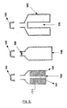
- the figure 3 schematically represents several steps of charging or recharging in the context of a vacuum deposition process. These charging or recharging steps occur while the chamber 1 is under vacuum, the valve 20 closing the orifice of the injector.
Landscapes
- Chemical & Material Sciences (AREA)
- Engineering & Computer Science (AREA)
- Materials Engineering (AREA)
- Metallurgy (AREA)
- Organic Chemistry (AREA)
- Chemical Kinetics & Catalysis (AREA)
- Mechanical Engineering (AREA)
- Crystallography & Structural Chemistry (AREA)
- Physical Vapour Deposition (AREA)
- Electroluminescent Light Sources (AREA)
Priority Applications (1)
| Application Number | Priority Date | Filing Date | Title |
|---|---|---|---|
| PL05824491T PL1825018T3 (pl) | 2004-12-07 | 2005-12-07 | Urządzenie do powlekania próżniowego ze zbiornikiem do ponownego ładowania i odpowiedni sposób powlekania próżniowego |
Applications Claiming Priority (2)
| Application Number | Priority Date | Filing Date | Title |
|---|---|---|---|
| FR0413025A FR2878863B1 (fr) | 2004-12-07 | 2004-12-07 | Dispositif de depot sous vide a reservoir de recharge et procede de depot sous vide correspondant. |
| PCT/FR2005/003072 WO2006061517A1 (fr) | 2004-12-07 | 2005-12-07 | Dispositif de depot sous vide a reservoir de recharge et procédé de dépôt sous vide correspondant |
Publications (2)
| Publication Number | Publication Date |
|---|---|
| EP1825018A1 EP1825018A1 (fr) | 2007-08-29 |
| EP1825018B1 true EP1825018B1 (fr) | 2013-07-10 |
Family
ID=34952572
Family Applications (1)
| Application Number | Title | Priority Date | Filing Date |
|---|---|---|---|
| EP05824491.4A Expired - Lifetime EP1825018B1 (fr) | 2004-12-07 | 2005-12-07 | Dispositif de dépôt sous vide a reservoir de recharge et procédé de dépôt sous vide correspondant |
Country Status (10)
| Country | Link |
|---|---|
| US (1) | US20080107811A1 (pl) |
| EP (1) | EP1825018B1 (pl) |
| JP (1) | JP2008523245A (pl) |
| KR (1) | KR101225867B1 (pl) |
| CN (1) | CN101111625B (pl) |
| DK (1) | DK1825018T3 (pl) |
| ES (1) | ES2429539T3 (pl) |
| FR (1) | FR2878863B1 (pl) |
| PL (1) | PL1825018T3 (pl) |
| WO (1) | WO2006061517A1 (pl) |
Families Citing this family (18)
| Publication number | Priority date | Publication date | Assignee | Title |
|---|---|---|---|---|
| KR100754404B1 (ko) * | 2006-05-25 | 2007-08-31 | 삼성전자주식회사 | 확산튜브와, 확산공정용 도펀트 소스 및 상기 확산튜브와도펀트 소스를 이용한 확산방법 |
| KR101263005B1 (ko) * | 2006-12-19 | 2013-05-08 | 비코 인스트루먼츠 인코포레이티드 | 증착 장치 및 방법 |
| JP5220091B2 (ja) * | 2008-02-26 | 2013-06-26 | 株式会社アルバック | 成膜源、蒸着装置、有機el素子の製造装置 |
| JP4880647B2 (ja) * | 2008-07-01 | 2012-02-22 | 東京エレクトロン株式会社 | 有機elの成膜装置および蒸着装置 |
| CN102209800A (zh) * | 2008-09-22 | 2011-10-05 | 贝克顿·迪金森公司 | 使用光解和/或热化学气相沉积法涂布容器内部的系统、设备和方法 |
| EP2186920A1 (en) | 2008-10-22 | 2010-05-19 | Applied Materials, Inc. | Arrangement and method for regulating a gas stream or the like |
| US20100098852A1 (en) * | 2008-10-22 | 2010-04-22 | Applied Materials, Inc. | Arrangement and method for regulating a gas stream or the like |
| EP2202435A1 (en) | 2008-12-19 | 2010-06-30 | Applied Materials, Inc. | Arrangement for the regulation of a gas stream |
| WO2010114118A1 (ja) * | 2009-04-03 | 2010-10-07 | 東京エレクトロン株式会社 | 蒸着ヘッドおよび成膜装置 |
| JP2014029005A (ja) * | 2012-07-05 | 2014-02-13 | Tokyo Electron Ltd | 成膜装置 |
| KR102007697B1 (ko) * | 2013-02-28 | 2019-08-06 | 삼성에스디아이 주식회사 | 이차전지용 전극 제조 장치 |
| FR3020381B1 (fr) | 2014-04-24 | 2017-09-29 | Riber | Cellule d'evaporation |
| KR102228880B1 (ko) * | 2014-05-12 | 2021-03-17 | 엘지전자 주식회사 | 증착 장치 |
| KR102099691B1 (ko) * | 2016-02-05 | 2020-04-10 | 주식회사 엘지화학 | 조절 가능한 밸브를 이용한 전지셀의 탈기 장치 및 이를 이용한 탈기 방법 |
| KR102030683B1 (ko) * | 2017-01-31 | 2019-10-10 | 어플라이드 머티어리얼스, 인코포레이티드 | 재료 증착 어레인지먼트, 진공 증착 시스템 및 이를 위한 방법 |
| CN110462096A (zh) * | 2017-04-21 | 2019-11-15 | 应用材料公司 | 材料沉积布置、用于沉积材料的方法和材料沉积腔室 |
| CN107012434A (zh) * | 2017-05-27 | 2017-08-04 | 武汉天马微电子有限公司 | 一种蒸发源及真空蒸镀装置 |
| CN112996946A (zh) * | 2018-12-04 | 2021-06-18 | 应用材料公司 | 用于蒸发材料的蒸发设备及使用蒸发设备蒸发材料的方法 |
Family Cites Families (25)
| Publication number | Priority date | Publication date | Assignee | Title |
|---|---|---|---|---|
| JPS51132074A (en) * | 1975-04-02 | 1976-11-16 | Toshiba Corp | Mercury emitting mechanism |
| US4553022A (en) | 1984-06-04 | 1985-11-12 | The Perkin-Elmer Corporation | Effusion cell assembly |
| US5019531A (en) * | 1988-05-23 | 1991-05-28 | Nippon Telegraph And Telephone Corporation | Process for selectively growing thin metallic film of copper or gold |
| US5156815A (en) * | 1988-09-08 | 1992-10-20 | Board Of Regents, The University Of Texas System | Sublimating and cracking apparatus |
| US5080870A (en) * | 1988-09-08 | 1992-01-14 | Board Of Regents, The University Of Texas System | Sublimating and cracking apparatus |
| US4948492A (en) * | 1989-05-01 | 1990-08-14 | General Electric Company | Electrode probe for use in aqueous environments of high temperature and high radiation |
| WO1992003588A1 (en) * | 1990-08-24 | 1992-03-05 | Dca Instruments Oy | Heater for an effusion cell |
| US5253266A (en) * | 1992-07-20 | 1993-10-12 | Intevac, Inc. | MBE effusion source with asymmetrical heaters |
| JP2719283B2 (ja) * | 1992-08-26 | 1998-02-25 | 隆文 八百 | 低温用クヌ−ドセンセル |
| US6101816A (en) * | 1998-04-28 | 2000-08-15 | Advanced Technology Materials, Inc. | Fluid storage and dispensing system |
| EP0962260B1 (en) * | 1998-05-28 | 2005-01-05 | Ulvac, Inc. | Material evaporation system |
| US6169422B1 (en) | 1998-07-20 | 2001-01-02 | Sun Microsystems, Inc. | Apparatus and methods for high throughput self-timed domino circuits |
| AU2522299A (en) * | 1999-02-05 | 2000-08-25 | Applied Films Gmbh & Co. Kg | Device for coating substrates with a vaporized material under low pressure or ina vacuum using a vaporized material source |
| DE10007059A1 (de) * | 2000-02-16 | 2001-08-23 | Aixtron Ag | Verfahren und Vorrichtung zur Herstellung von beschichteten Substraten mittels Kondensationsbeschichtung |
| EP1249163A1 (en) * | 2001-04-09 | 2002-10-16 | Zelnova, S.A. | Thermal vaporizer for a liquid formulation comprising a volatile active |
| JP3616586B2 (ja) * | 2001-07-19 | 2005-02-02 | 株式会社日本ビーテック | 薄膜堆積用分子線源セル |
| JP3684343B2 (ja) * | 2001-09-25 | 2005-08-17 | 株式会社日本ビーテック | 薄膜堆積用分子線源セル |
| CN1421542A (zh) * | 2001-11-29 | 2003-06-04 | 电子科技大学 | 有机材料蒸发源 |
| KR100829736B1 (ko) * | 2002-02-07 | 2008-05-15 | 삼성에스디아이 주식회사 | 진공 증착장치의 가열용기 |
| EP1369499A3 (en) * | 2002-04-15 | 2004-10-20 | Semiconductor Energy Laboratory Co., Ltd. | Method of fabricating light-emitting device and apparatus for manufacturing light-emitting device |
| US6749906B2 (en) * | 2002-04-25 | 2004-06-15 | Eastman Kodak Company | Thermal physical vapor deposition apparatus with detachable vapor source(s) and method |
| US6686595B2 (en) * | 2002-06-26 | 2004-02-03 | Semequip Inc. | Electron impact ion source |
| TWI277363B (en) * | 2002-08-30 | 2007-03-21 | Semiconductor Energy Lab | Fabrication system, light-emitting device and fabricating method of organic compound-containing layer |
| JP2004260174A (ja) * | 2003-02-25 | 2004-09-16 | Samsung Electronics Co Ltd | 半導体素子製造装置 |
| CN2619451Y (zh) * | 2003-05-08 | 2004-06-02 | 深圳市创欧科技有限公司 | 用于制作有机电致发光显示器的蒸镀装置 |
-
2004
- 2004-12-07 FR FR0413025A patent/FR2878863B1/fr not_active Expired - Fee Related
-
2005
- 2005-12-07 KR KR1020077015349A patent/KR101225867B1/ko not_active Expired - Lifetime
- 2005-12-07 CN CN2005800474524A patent/CN101111625B/zh not_active Expired - Fee Related
- 2005-12-07 ES ES05824491T patent/ES2429539T3/es not_active Expired - Lifetime
- 2005-12-07 JP JP2007544946A patent/JP2008523245A/ja active Pending
- 2005-12-07 DK DK05824491.4T patent/DK1825018T3/da active
- 2005-12-07 EP EP05824491.4A patent/EP1825018B1/fr not_active Expired - Lifetime
- 2005-12-07 PL PL05824491T patent/PL1825018T3/pl unknown
- 2005-12-07 US US11/792,554 patent/US20080107811A1/en not_active Abandoned
- 2005-12-07 WO PCT/FR2005/003072 patent/WO2006061517A1/fr not_active Ceased
Also Published As
| Publication number | Publication date |
|---|---|
| PL1825018T3 (pl) | 2014-01-31 |
| DK1825018T3 (da) | 2013-10-07 |
| JP2008523245A (ja) | 2008-07-03 |
| ES2429539T3 (es) | 2013-11-15 |
| CN101111625B (zh) | 2010-09-29 |
| EP1825018A1 (fr) | 2007-08-29 |
| FR2878863B1 (fr) | 2007-11-23 |
| FR2878863A1 (fr) | 2006-06-09 |
| KR101225867B1 (ko) | 2013-01-24 |
| US20080107811A1 (en) | 2008-05-08 |
| WO2006061517A1 (fr) | 2006-06-15 |
| CN101111625A (zh) | 2008-01-23 |
| KR20070086933A (ko) | 2007-08-27 |
Similar Documents
| Publication | Publication Date | Title |
|---|---|---|
| EP1825018B1 (fr) | Dispositif de dépôt sous vide a reservoir de recharge et procédé de dépôt sous vide correspondant | |
| EP2618675B1 (fr) | Dispositif de thermonébulisation d'un liquide et procédé associé | |
| EP2682503B1 (fr) | Dispositif d'évaporation pour appareil de dépôt sous vide et appareil de dépôt sous vide comprenant un tel dispositif d'évaporation | |
| EP0041975B1 (fr) | Pistolet perfectionne pour l'application de peintures a chaud | |
| EP0249516A1 (fr) | Cellule pour épitaxie par jets moléculaires et procédé associé | |
| WO2013057443A1 (fr) | Systeme d'injection pour dispositif de depot de couches minces par evaporation sous vide | |
| EP2915897A1 (fr) | Procédé de rechargement d'une cellule d'évaporation | |
| FR3020381A1 (fr) | Cellule d'evaporation | |
| CA1217708A (fr) | Dispositif de distribution de liquide cryogenique | |
| FR2766558A1 (fr) | Dispositif de production d'eau chaude | |
| EP0613955B1 (fr) | Dispositif de chargement avec organe de réglage du débit | |
| EP1393351A1 (fr) | Procede et dispositif de dopage, diffusion et oxydation de plaquettes de silicium a pression reduite | |
| FR2468007A1 (fr) | Pompe cryogenique et collecteur cryogenique pour la collecte d'echantillons d'air et dispositif a sas adapte | |
| FR2562099A1 (fr) | Cellule d'evaporation d'un compose liquide adaptee a l'epitaxie par jets moleculaires | |
| EP3890564B1 (fr) | Accessoire cuiseur vapeur avec double couronne turbo | |
| EP3601909B1 (fr) | Dispositif de refroidissement | |
| EP0692684B1 (fr) | Dispositif de génération d'un courant d'air chaud | |
| EP3010850A1 (fr) | Bec de remplissage multi-jet a event integre | |
| LU83874A1 (fr) | Pulverisateur de liquide sur roues demontable | |
| EP0264310A2 (fr) | Chaudière pour la production d'eau chaude | |
| CA2153518C (fr) | Dispositif de generation d'un courant d'air chaud | |
| WO2002081787A1 (fr) | Reservoir pour installation d'epitaxie et installation comprenant un tel reservoir | |
| FR2630259A1 (fr) | Dispositif d'evaporation du mercure sous vide a un niveau constant pour cellule destinee a la croissance epitaxiale de semi-conducteurs | |
| EP4166632A1 (fr) | Système de conversion thermochimique d'une charge carbonée comprenant un réacteur batch et un réservoir d attente contenant un fluide supercritique relié à la chambre réactionnelle du réacteur batch | |
| CH529326A (fr) | Appareillage pour le maintien d'une température déterminée à l'intérieur d'une enceinte réfrigérée |
Legal Events
| Date | Code | Title | Description |
|---|---|---|---|
| PUAI | Public reference made under article 153(3) epc to a published international application that has entered the european phase |
Free format text: ORIGINAL CODE: 0009012 |
|
| 17P | Request for examination filed |
Effective date: 20070612 |
|
| AK | Designated contracting states |
Kind code of ref document: A1 Designated state(s): AT BE BG CH CY CZ DE DK EE ES FI FR GB GR HU IE IS IT LI LT LU LV MC NL PL PT RO SE SI SK TR |
|
| DAX | Request for extension of the european patent (deleted) | ||
| REG | Reference to a national code |
Ref country code: DE Ref legal event code: R079 Ref document number: 602005040375 Country of ref document: DE Free format text: PREVIOUS MAIN CLASS: C23C0014240000 Ipc: C30B0023060000 |
|
| RIC1 | Information provided on ipc code assigned before grant |
Ipc: C30B 29/54 20060101ALI20121010BHEP Ipc: C23C 14/26 20060101ALI20121010BHEP Ipc: C30B 23/06 20060101AFI20121010BHEP Ipc: C23C 14/24 20060101ALI20121010BHEP |
|
| GRAP | Despatch of communication of intention to grant a patent |
Free format text: ORIGINAL CODE: EPIDOSNIGR1 |
|
| RIN1 | Information on inventor provided before grant (corrected) |
Inventor name: STEMMELEN, FRANCK Inventor name: GUYAUX, JEAN-LOUIS Inventor name: BOUCHAIB, PIERRE |
|
| GRAP | Despatch of communication of intention to grant a patent |
Free format text: ORIGINAL CODE: EPIDOSNIGR1 |
|
| RAP1 | Party data changed (applicant data changed or rights of an application transferred) |
Owner name: RIBER S.A. |
|
| GRAS | Grant fee paid |
Free format text: ORIGINAL CODE: EPIDOSNIGR3 |
|
| GRAA | (expected) grant |
Free format text: ORIGINAL CODE: 0009210 |
|
| AK | Designated contracting states |
Kind code of ref document: B1 Designated state(s): AT BE BG CH CY CZ DE DK EE ES FI FR GB GR HU IE IS IT LI LT LU LV MC NL PL PT RO SE SI SK TR |
|
| REG | Reference to a national code |
Ref country code: GB Ref legal event code: FG4D Free format text: NOT ENGLISH |
|
| REG | Reference to a national code |
Ref country code: CH Ref legal event code: EP Ref country code: AT Ref legal event code: REF Ref document number: 621041 Country of ref document: AT Kind code of ref document: T Effective date: 20130715 |
|
| REG | Reference to a national code |
Ref country code: IE Ref legal event code: FG4D Free format text: LANGUAGE OF EP DOCUMENT: FRENCH |
|
| REG | Reference to a national code |
Ref country code: DE Ref legal event code: R096 Ref document number: 602005040375 Country of ref document: DE Effective date: 20130905 |
|
| REG | Reference to a national code |
Ref country code: CH Ref legal event code: NV Representative=s name: KIRKER AND CIE S.A., CH |
|
| REG | Reference to a national code |
Ref country code: DK Ref legal event code: T3 Effective date: 20131003 Ref country code: DK Ref legal event code: T3 |
|
| REG | Reference to a national code |
Ref country code: SE Ref legal event code: TRGR |
|
| PG25 | Lapsed in a contracting state [announced via postgrant information from national office to epo] |
Ref country code: SI Free format text: LAPSE BECAUSE OF FAILURE TO SUBMIT A TRANSLATION OF THE DESCRIPTION OR TO PAY THE FEE WITHIN THE PRESCRIBED TIME-LIMIT Effective date: 20130710 |
|
| REG | Reference to a national code |
Ref country code: NL Ref legal event code: T3 |
|
| REG | Reference to a national code |
Ref country code: ES Ref legal event code: FG2A Ref document number: 2429539 Country of ref document: ES Kind code of ref document: T3 Effective date: 20131115 |
|
| REG | Reference to a national code |
Ref country code: CH Ref legal event code: PK Free format text: RECTIFICATION TITULAIRE |
|
| REG | Reference to a national code |
Ref country code: LT Ref legal event code: MG4D |
|
| RAP2 | Party data changed (patent owner data changed or rights of a patent transferred) |
Owner name: RIBER |
|
| PG25 | Lapsed in a contracting state [announced via postgrant information from national office to epo] |
Ref country code: LT Free format text: LAPSE BECAUSE OF FAILURE TO SUBMIT A TRANSLATION OF THE DESCRIPTION OR TO PAY THE FEE WITHIN THE PRESCRIBED TIME-LIMIT Effective date: 20130710 Ref country code: CY Free format text: LAPSE BECAUSE OF FAILURE TO SUBMIT A TRANSLATION OF THE DESCRIPTION OR TO PAY THE FEE WITHIN THE PRESCRIBED TIME-LIMIT Effective date: 20130724 Ref country code: IS Free format text: LAPSE BECAUSE OF FAILURE TO SUBMIT A TRANSLATION OF THE DESCRIPTION OR TO PAY THE FEE WITHIN THE PRESCRIBED TIME-LIMIT Effective date: 20131110 Ref country code: PT Free format text: LAPSE BECAUSE OF FAILURE TO SUBMIT A TRANSLATION OF THE DESCRIPTION OR TO PAY THE FEE WITHIN THE PRESCRIBED TIME-LIMIT Effective date: 20131111 |
|
| REG | Reference to a national code |
Ref country code: PL Ref legal event code: T3 |
|
| PG25 | Lapsed in a contracting state [announced via postgrant information from national office to epo] |
Ref country code: GR Free format text: LAPSE BECAUSE OF FAILURE TO SUBMIT A TRANSLATION OF THE DESCRIPTION OR TO PAY THE FEE WITHIN THE PRESCRIBED TIME-LIMIT Effective date: 20131011 Ref country code: LV Free format text: LAPSE BECAUSE OF FAILURE TO SUBMIT A TRANSLATION OF THE DESCRIPTION OR TO PAY THE FEE WITHIN THE PRESCRIBED TIME-LIMIT Effective date: 20130710 |
|
| PGFP | Annual fee paid to national office [announced via postgrant information from national office to epo] |
Ref country code: TR Payment date: 20131126 Year of fee payment: 9 |
|
| PG25 | Lapsed in a contracting state [announced via postgrant information from national office to epo] |
Ref country code: CY Free format text: LAPSE BECAUSE OF FAILURE TO SUBMIT A TRANSLATION OF THE DESCRIPTION OR TO PAY THE FEE WITHIN THE PRESCRIBED TIME-LIMIT Effective date: 20130710 |
|
| PG25 | Lapsed in a contracting state [announced via postgrant information from national office to epo] |
Ref country code: RO Free format text: LAPSE BECAUSE OF FAILURE TO SUBMIT A TRANSLATION OF THE DESCRIPTION OR TO PAY THE FEE WITHIN THE PRESCRIBED TIME-LIMIT Effective date: 20130710 Ref country code: SK Free format text: LAPSE BECAUSE OF FAILURE TO SUBMIT A TRANSLATION OF THE DESCRIPTION OR TO PAY THE FEE WITHIN THE PRESCRIBED TIME-LIMIT Effective date: 20130710 Ref country code: EE Free format text: LAPSE BECAUSE OF FAILURE TO SUBMIT A TRANSLATION OF THE DESCRIPTION OR TO PAY THE FEE WITHIN THE PRESCRIBED TIME-LIMIT Effective date: 20130710 |
|
| PLBE | No opposition filed within time limit |
Free format text: ORIGINAL CODE: 0009261 |
|
| STAA | Information on the status of an ep patent application or granted ep patent |
Free format text: STATUS: NO OPPOSITION FILED WITHIN TIME LIMIT |
|
| 26N | No opposition filed |
Effective date: 20140411 |
|
| REG | Reference to a national code |
Ref country code: HU Ref legal event code: AG4A Ref document number: E019235 Country of ref document: HU |
|
| REG | Reference to a national code |
Ref country code: DE Ref legal event code: R097 Ref document number: 602005040375 Country of ref document: DE Effective date: 20140411 |
|
| PG25 | Lapsed in a contracting state [announced via postgrant information from national office to epo] |
Ref country code: MC Free format text: LAPSE BECAUSE OF FAILURE TO SUBMIT A TRANSLATION OF THE DESCRIPTION OR TO PAY THE FEE WITHIN THE PRESCRIBED TIME-LIMIT Effective date: 20130710 Ref country code: LU Free format text: LAPSE BECAUSE OF FAILURE TO SUBMIT A TRANSLATION OF THE DESCRIPTION OR TO PAY THE FEE WITHIN THE PRESCRIBED TIME-LIMIT Effective date: 20131207 |
|
| PGFP | Annual fee paid to national office [announced via postgrant information from national office to epo] |
Ref country code: IE Payment date: 20140904 Year of fee payment: 10 Ref country code: DK Payment date: 20140912 Year of fee payment: 10 |
|
| PGFP | Annual fee paid to national office [announced via postgrant information from national office to epo] |
Ref country code: SE Payment date: 20140912 Year of fee payment: 10 |
|
| PGFP | Annual fee paid to national office [announced via postgrant information from national office to epo] |
Ref country code: CH Payment date: 20141111 Year of fee payment: 10 Ref country code: CZ Payment date: 20141203 Year of fee payment: 10 Ref country code: ES Payment date: 20141010 Year of fee payment: 10 |
|
| PGFP | Annual fee paid to national office [announced via postgrant information from national office to epo] |
Ref country code: HU Payment date: 20141219 Year of fee payment: 10 Ref country code: PL Payment date: 20141028 Year of fee payment: 10 Ref country code: AT Payment date: 20141010 Year of fee payment: 10 Ref country code: NL Payment date: 20141219 Year of fee payment: 10 |
|
| PGFP | Annual fee paid to national office [announced via postgrant information from national office to epo] |
Ref country code: IT Payment date: 20141219 Year of fee payment: 10 |
|
| PGFP | Annual fee paid to national office [announced via postgrant information from national office to epo] |
Ref country code: BE Payment date: 20141020 Year of fee payment: 10 |
|
| PG25 | Lapsed in a contracting state [announced via postgrant information from national office to epo] |
Ref country code: BG Free format text: LAPSE BECAUSE OF FAILURE TO SUBMIT A TRANSLATION OF THE DESCRIPTION OR TO PAY THE FEE WITHIN THE PRESCRIBED TIME-LIMIT Effective date: 20130710 |
|
| PG25 | Lapsed in a contracting state [announced via postgrant information from national office to epo] |
Ref country code: BE Free format text: LAPSE BECAUSE OF NON-PAYMENT OF DUE FEES Effective date: 20151231 |
|
| REG | Reference to a national code |
Ref country code: DK Ref legal event code: EBP Effective date: 20151231 |
|
| PG25 | Lapsed in a contracting state [announced via postgrant information from national office to epo] |
Ref country code: CZ Free format text: LAPSE BECAUSE OF NON-PAYMENT OF DUE FEES Effective date: 20151207 |
|
| REG | Reference to a national code |
Ref country code: CH Ref legal event code: PL |
|
| REG | Reference to a national code |
Ref country code: SE Ref legal event code: EUG |
|
| REG | Reference to a national code |
Ref country code: AT Ref legal event code: MM01 Ref document number: 621041 Country of ref document: AT Kind code of ref document: T Effective date: 20151207 |
|
| PG25 | Lapsed in a contracting state [announced via postgrant information from national office to epo] |
Ref country code: SE Free format text: LAPSE BECAUSE OF NON-PAYMENT OF DUE FEES Effective date: 20151208 |
|
| REG | Reference to a national code |
Ref country code: FR Ref legal event code: PLFP Year of fee payment: 12 |
|
| REG | Reference to a national code |
Ref country code: NL Ref legal event code: MM Effective date: 20160101 |
|
| REG | Reference to a national code |
Ref country code: IE Ref legal event code: MM4A |
|
| PG25 | Lapsed in a contracting state [announced via postgrant information from national office to epo] |
Ref country code: IE Free format text: LAPSE BECAUSE OF NON-PAYMENT OF DUE FEES Effective date: 20151207 Ref country code: LI Free format text: LAPSE BECAUSE OF NON-PAYMENT OF DUE FEES Effective date: 20151231 Ref country code: CH Free format text: LAPSE BECAUSE OF NON-PAYMENT OF DUE FEES Effective date: 20151231 Ref country code: HU Free format text: LAPSE BECAUSE OF NON-PAYMENT OF DUE FEES Effective date: 20151208 Ref country code: NL Free format text: LAPSE BECAUSE OF NON-PAYMENT OF DUE FEES Effective date: 20160101 |
|
| PG25 | Lapsed in a contracting state [announced via postgrant information from national office to epo] |
Ref country code: AT Free format text: LAPSE BECAUSE OF NON-PAYMENT OF DUE FEES Effective date: 20151207 |
|
| PG25 | Lapsed in a contracting state [announced via postgrant information from national office to epo] |
Ref country code: IT Free format text: LAPSE BECAUSE OF NON-PAYMENT OF DUE FEES Effective date: 20151207 |
|
| PG25 | Lapsed in a contracting state [announced via postgrant information from national office to epo] |
Ref country code: DK Free format text: LAPSE BECAUSE OF NON-PAYMENT OF DUE FEES Effective date: 20151231 |
|
| PG25 | Lapsed in a contracting state [announced via postgrant information from national office to epo] |
Ref country code: PL Free format text: LAPSE BECAUSE OF NON-PAYMENT OF DUE FEES Effective date: 20151207 |
|
| PG25 | Lapsed in a contracting state [announced via postgrant information from national office to epo] |
Ref country code: ES Free format text: LAPSE BECAUSE OF NON-PAYMENT OF DUE FEES Effective date: 20151208 |
|
| PG25 | Lapsed in a contracting state [announced via postgrant information from national office to epo] |
Ref country code: TR Free format text: LAPSE BECAUSE OF NON-PAYMENT OF DUE FEES Effective date: 20151207 |
|
| REG | Reference to a national code |
Ref country code: FR Ref legal event code: PLFP Year of fee payment: 13 |
|
| REG | Reference to a national code |
Ref country code: DE Ref legal event code: R082 Ref document number: 602005040375 Country of ref document: DE Representative=s name: KEIL & SCHAAFHAUSEN PATENTANWAELTE PARTGMBB, DE Ref country code: DE Ref legal event code: R082 Ref document number: 602005040375 Country of ref document: DE Representative=s name: KEIL & SCHAAFHAUSEN PATENT- UND RECHTSANWAELTE, DE |
|
| REG | Reference to a national code |
Ref country code: ES Ref legal event code: FD2A Effective date: 20180704 |
|
| REG | Reference to a national code |
Ref country code: FR Ref legal event code: PLFP Year of fee payment: 14 |
|
| PGFP | Annual fee paid to national office [announced via postgrant information from national office to epo] |
Ref country code: FI Payment date: 20240906 Year of fee payment: 20 |
|
| PGFP | Annual fee paid to national office [announced via postgrant information from national office to epo] |
Ref country code: FR Payment date: 20240905 Year of fee payment: 20 |
|
| PGFP | Annual fee paid to national office [announced via postgrant information from national office to epo] |
Ref country code: DE Payment date: 20240906 Year of fee payment: 20 |
|
| PGFP | Annual fee paid to national office [announced via postgrant information from national office to epo] |
Ref country code: GB Payment date: 20241001 Year of fee payment: 20 |
|
| REG | Reference to a national code |
Ref country code: DE Ref legal event code: R071 Ref document number: 602005040375 Country of ref document: DE |
|
| REG | Reference to a national code |
Ref country code: GB Ref legal event code: PE20 Expiry date: 20251206 |