EP1825660B1 - Verfahren und system für abstandsmessungen - Google Patents
Verfahren und system für abstandsmessungen Download PDFInfo
- Publication number
- EP1825660B1 EP1825660B1 EP05796764.8A EP05796764A EP1825660B1 EP 1825660 B1 EP1825660 B1 EP 1825660B1 EP 05796764 A EP05796764 A EP 05796764A EP 1825660 B1 EP1825660 B1 EP 1825660B1
- Authority
- EP
- European Patent Office
- Prior art keywords
- line
- telephone
- terminal
- telephone line
- measurement device
- Prior art date
- Legal status (The legal status is an assumption and is not a legal conclusion. Google has not performed a legal analysis and makes no representation as to the accuracy of the status listed.)
- Expired - Lifetime
Links
Images


Classifications
-
- H—ELECTRICITY
- H04—ELECTRIC COMMUNICATION TECHNIQUE
- H04M—TELEPHONIC COMMUNICATION
- H04M3/00—Automatic or semi-automatic exchanges
- H04M3/22—Arrangements for supervision, monitoring or testing
- H04M3/2209—Arrangements for supervision, monitoring or testing for lines also used for data transmission
-
- H—ELECTRICITY
- H04—ELECTRIC COMMUNICATION TECHNIQUE
- H04M—TELEPHONIC COMMUNICATION
- H04M3/00—Automatic or semi-automatic exchanges
- H04M3/22—Arrangements for supervision, monitoring or testing
- H04M3/26—Arrangements for supervision, monitoring or testing with means for applying test signals or for measuring
- H04M3/28—Automatic routine testing ; Fault testing; Installation testing; Test methods, test equipment or test arrangements therefor
- H04M3/30—Automatic routine testing ; Fault testing; Installation testing; Test methods, test equipment or test arrangements therefor for subscriber's lines, for the local loop
- H04M3/305—Automatic routine testing ; Fault testing; Installation testing; Test methods, test equipment or test arrangements therefor for subscriber's lines, for the local loop testing of physical copper line parameters, e.g. capacitance or resistance
- H04M3/306—Automatic routine testing ; Fault testing; Installation testing; Test methods, test equipment or test arrangements therefor for subscriber's lines, for the local loop testing of physical copper line parameters, e.g. capacitance or resistance for frequencies above the voice frequency, e.g. xDSL line qualification
-
- G—PHYSICS
- G01—MEASURING; TESTING
- G01R—MEASURING ELECTRIC VARIABLES; MEASURING MAGNETIC VARIABLES
- G01R31/00—Arrangements for testing electric properties; Arrangements for locating electric faults; Arrangements for electrical testing characterised by what is being tested not provided for elsewhere
- G01R31/50—Testing of electric apparatus, lines, cables or components for short-circuits, continuity, leakage current or incorrect line connections
- G01R31/58—Testing of lines, cables or conductors
Definitions
- TDR time domain reflectometer
- frequency domain measurements are usually being carried without automation.
- the twisted pair wire connected to a telephone line card of the switch is manually disconnected from the line card.
- the line testing device such as, time domain reflectometer (TDR) is then connected to the open end of the line and accordingly the measurement is performed as if the telephone line is an unused spare line.
- TDR measurements are performed on unused or disconnected wire pairs as to avoid echo pulses or interference from active devices, such as the telephone line cards. After completion of the measurement, the twisted pair wire is manually reconnected to the line card.
- An existing solution which enables some automation of the line testing process involves the installation of a disconnection automated unit, such as a matrix, within the existing infrastructure of the telephone operating company (TELCO).
- TELCO telephone operating company
- US 6026145 describes a method of testing subscriber lines by connecting a measurement hardware to one or more individual subscriber lines via a switch unit and transmitting a signal down said individual line and recording the reflected signal.
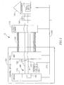
- Fig. 1 is a simplified block-diagram of a portion of a POTS network having a testing device according to some embodiments of the present invention
- Fig. 2 is a block-diagram illustration of the testing device of Fig. 1 according to some embodiments of the present invention
- Fig. 3 is a block-diagram illustration of a test configuration unit according to some embodiments of the present invention.
- Fig. 4 is a block-diagram illustration of another test configuration unit according to some embodiments of the present invention.
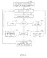
- Fig. 5 is flowchart diagram illustration of the line qualification method according to some embodiments of the present invention.
- a method comprising identifying that an active telephone line that interconnects a telephone line card with a subscriber does not carry telephone signals; electrically connecting a first terminal of a measurement device, to both wires of a twisted wire pair of the telephone line and causing short-circuiting between said wires; electrically connecting a second terminal of said measurement device to a common reference; and performing an impairment line testing on said telephone line from said measurement device toward said subscriber while the first terminal is connected to said both wires of the twisted wire pair and the second terminal is connected to the common reference by transmitting a signal and receiving a reflected signal via the first terminal along both wires of the telephone line.
- Network 10 may comprise TELCO environment 100 having a switch 110 and a main distribution frame (MDF) 120.
- Network 10 may further comprise a subscriber premises 130, a distribution point (DP) 140 coupled to subscriber premises 130 and a street cabinet 150 coupled to DP 140.
- MDF main distribution frame
- DP distribution point
- Switch 110 may comprise telephone line cards, such as line card 160 to connect a termination device 170 within subscriber premises 130 to the telephone network 10 using a subscriber line 180.
- Subscriber line 180 may be additionally referred to as an active telephone line.
- subscriber line refers to the entire line interconnecting the line card with the subscriber or portions thereof.
- active telephone line refers to a telephone line that interconnects a telephone line card with a subscriber.
- Subscriber line 180 may comprise a standard twisted two-wire telephone line also referred to as a twisted pair wire. The two wires are generally referred to as the ring (R) and the tip (T) wires.
- Subscriber line 180 may exit telephone line card 160 and may connect line card 160 to MDF 120 using a twisted pair wire.
- Other sections of subscriber line 180 may be housed within a multi pair cable carrying a plurality of lines in a closed packed configuration.
- the section of subscriber line 180 between MDF 120 and street cabinet 150 is housed within a multi pair cable 190.
- unused twisted pair wires housed within multi pair cable 190 as spare lines for future use may connect street cabinet 150 only to MDF 120 without being connected to switch 110.
- TELCO environment 100 may further comprise a testing device 200 connectable to subscriber line 180.
- the testing device is connectable to the subscriber line within the TELCO environment
- the testing device may be connectable to subscriber line at other locations along the telephone line.
- the testing device may be connected to subscriber line 180 such that a first terminal 210 is connected to both the tip and ring wires at location 230 and a second terminal 220 is connected to a ground reference 240, as shown in, Fig. 1 .
- Such a configuration which may involve a short circuit between the two wires of a twisted wire pair, may emulate an off-hook line state. Accordingly, the interference of the line card to the measurement results may be neutralized.
- the ground reference which is a common reference plane for the cable itself, the TELCO environment, the street cabinet and the subscriber premises, closes the electrical circuit required for the measurement, from the access point at the TELCO environment to the termination device and back. It should, however, be understood to a person skilled in the art that any common reference plane may be used.
- FIG. 2 is a block-diagram illustration of the testing device of Fig. 1 coupled via a front tap shoe connector to an MDF block according to some embodiments of the present invention.
- testing device 200 may access the telephone lines coupled to MDF 120 using front tap shoe connectors, such as, for example, various shoe connectors designed by RiT technologies of Tel-Aviv, Israel.
- the shoe may include a plurality of contacts, for example 100 contacts, simultaneously connectable a plurality of twisted wire pairs.
- testing device 200 is coupled to an MDF block 250 through a front tap shoe connector 260. It should be understood to a person skilled in the art that more than one shoe may be concurrently connected to the testing device for automatic handling of a larger amount of telephone lines.
- a multi pair cable 270 which may hold a plurality of twisted wires pairs may connect shoe connector 260 and testing device 200. According to embodiments of the present invention, once shoe connector 260 is connected to the testing device 200, the mass qualification test of all the telephone lines coupled to the shoe connector may be carried out automatically without further human interference, as described below in relation to Fig. 5 .
- Testing device 200 may comprise a front-end unit 280, a measurement unit 290, such as TDR unit, coupled to front-end unit 280 and a controller 300, which may be a portable personal computer. Controller 300 may be coupled to both measurement unit 290 and to front-end unit 280.
- Measurement unit 290 may be a conventional TDR.
- TDR operates by transmitting pulse signals along a wire pair and measuring the reflection to determine discontinuity at the transmission line by identifying changes in the impedance of the wire pair.
- the TDR comprises a pulse generator to generate and transmit the pulses when instructed by controller 300 and a signal receiver to receive the reflected pulse, when a reflection occurs. Then, the TDR measures the amplitude of the reflected pulse and the time interval between the transmission of the pulse and the reception of the reflected pulse. The measured time interval is used to determine the distance from the location of transmission to the location of the event, namely an impedance discontinuity that caused the reflection. Such events may be the termination of the telephone line at the termination device or other impairments along the line.
- Front-end unit 280 may comprise a line selector 310 having an array of relays.
- Line selector 310 may be able to automatically select one of the twisted wires pairs held by multi pair cable 270 and to connect the selected pair to measurement unit 290 for line testing.
- Front-end unit 280 may further comprise a line status detector 320, such as, for example a direct current (DC) voltmeter or a spectral analysis unit. As the tested telephone line remains connected to the telephone line card, it may be busy carrying voice to its corresponding termination device at any time. In order to avoid interference to busy telephone lines, line status detector 320 may execute a preliminary voltage measurement on the selected telephone line before starting the distance measurement testing to determine the status of the selected telephone line.
- DC direct current
- line status detector 320 may identify the type of the selected telephone line as being either a digital or an analog line. Although not specifically mentioned, it should be understood to a person skilled in the art that line status detector 320 may perform additional measurements for digital service identification, such as, for example spectral analysis measurements.
- Front-end unit 280 may further comprise a configuration unit 330 coupled to line selector 310 and to measurement unit 290.
- Configuration unit 330 is able to connect the selected tip and ring wires to measurement unit 290 in various test configurations, as required, based on the status of the telephone line.
- Configuration unit 330 may comprise a plurality of two-state relays S1, S2, S3, S4, S5, S6, S7 and S8 to enable various test configurations. For example, by selecting to close two-state relays S1 and S2, each of the ring and tip wires is connected to a different terminal at measurement unit 290 and accordingly a conventional impairment line testing may be performed from the measurement unit toward the line termination at the subscriber premises.
- Another useful configuration for performing the line testing according to embodiments of the present invention may involve selecting to close two-state relays S3 and S4 and as a result electrically connecting the tip and ring wires.
- electrically connecting the tip and ring may cause short-circuiting between the tip and ring wires.
- Further selecting to close two-state relays S5 or S6 may connect both the electrically connected tip and ring wires to a selected one of the terminals of measurement unit 290.
- the selection of closing two-state relays S7 or S8 may connect the ground plane to the remaining terminal of measurement unit 290. Accordingly, before performing the line testing for an active telephone line coupled to an active telephone line card without disconnecting the telephone line from the telephone line card, a possible configuration may involve closing two-state relays S3, S4, S5 and S8 while all other two-state relays remain open.
- front-end unit 280 may further comprise a controller interface unit 340 coupled to line selector 310, line status detector 320, configuration unit 330, measurement unit 290 and to controller 300.
- Controller 300 which may be a standard portable personal computer, may send hardware commands to the other units and may receive data relating to the measurement testing for data processing.
- Control interface unit 340 may translate the commands received by controller 300 into switching command signals by using digital circuitry, as known in the art.
- a test configuration unit 400 may comprise two-state relays S1 - S12 to enable various test configurations and a splitter 410.
- Splitter 410 may be connectable to the tip and ring wires of subscriber line 180 on one end and to measurement unit 290 on the other end.
- Splitter 410 may prevent signals at low band (voice) frequencies below a predetermined threshold to be transmitted from measurement unit 290 along subscriber line 180 toward subscriber 130 or line card 160.
- splitter 410 may provide very low impedance, which may emulate a sort-circuit between the tip and ring wires at high frequencies corresponding to the TDR band. Consequently, test configuration unit 400 may enable performing an impairment line testing by transmitting high frequencies (TDR band) to the subscriber line 180 while voice may be carried by the tested subscriber line without interruption to the telephone line service.
- TDR band high frequencies
- the splitter mode operation described above may be performed when two-state relays S9, S10, S11 and S8 while all other two-state relays remain open.
- the filter mode operation described above may be performed when two-state relays S9, S10, S12 and S7 while all other two-state relays remain open.
- FIG. 5 is a flow-chart diagram of a line testing method according to some embodiments of the present invention.
- controller 300 may instruct line selector 310 to select one of the wire pairs connected to the testing device (block 510).
- controller 300 may instruct line status detector 320 to identify the type of telephone line selected and the status of the line (block 520).
- controller 300 may instruct configuration unit 330 to connect measurement unit 290 to the selected telephone line such that a first terminal of the measurement unit is connected to the tip wire and a second terminal of the measurement unit is connected to the ring wire. Controller 300 may then instruct measurement unit 290 to transmit a signal along subscriber line 180 toward subscriber 130 and to complete the line testing of the selected line (block 540).
- the selected telephone line may be identified as an active line coupled a telephone line card at the switch and as an unoccupied line (not carrying voice) (block 550). If the selected telephone line is identifies as such, controller 300 may instruct the configuration unit to enable connection between measurement unit 290 and the selected twisted wire pair in a different manner.
- a first terminal of the measurement unit is connected to both the tip and ring wires and a second terminal of the measurement unit is connected to a ground reference.
- Controller 300 may then instruct measurement unit 290 to transmit a signal along subscriber line 180 toward the line termination and to complete the line testing of the selected line (block 560). This operation may occupy the telephone line for several seconds, in which the telephone service is not enabled.
- the testing device comprises splitter 400, the impairment line testing may be performed without occupying the telephone line and without any interference to the telephone service..
- the selected telephone line may be identified as an active line coupled a telephone line card at the switch and as an occupied line (carrying voice) block 570). If the selected telephone line is identifies as such, controller 300 may instruct line selector 310 to select another telephone line.
- the testing device is pre-designed such that line selector 310 may reselect the occupied telephone line at a later stage (block 580). Alternatively, if the testing device comprises splitter 400, the impairment line testing may be performed also for an occupied telephone line.
- controller 300 may instruct line selector 310 to disconnect the selected wire pair and to select another twisted wire pair for automatic continuation of the mass line qualification testing. It should be noted that the operations described for a particular selected twisted pair may be terminated within a few seconds.
Landscapes
- Engineering & Computer Science (AREA)
- Signal Processing (AREA)
- Computer Networks & Wireless Communication (AREA)
- Monitoring And Testing Of Exchanges (AREA)
Claims (13)
- Verfahren, umfassend:Identifizieren, dass eine aktive Telefonleitung (180), die eine Telefonleitungskarte (160) mit einem Teilnehmer (130) verbindet, keine Telefonsignale führt;elektrisch Verbinden eines ersten Anschlusses (210) eines Messgeräts (200) mit beiden Drähten eines verdrillten Drahtpaares von der Telefonleitung (180) und Verursachen eines Kurzschlusses zwischen den Drähten;elektrisches Verbinden eines zweiten Anschlusses (220) des Messgeräts (200) mit einem gemeinsamen Bezugspunkt; undDurchführen einer Leitungsprüfung auf Beeinträchtigung der Telefonleitung (180) von der Messeinrichtung (200) zu dem Teilnehmer (130), während der erste Anschluss (210) mit den beiden Drähten des verdrillten Drahtpaars (180) verbunden ist und der zweite Anschluss (220) mit dem gemeinsamen Bezugspunkt verbunden ist, durch Übertragen eines Signals und Empfangen eines reflektierten Signals über den ersten Anschluss (210) entlang der beiden Drähte der Telefonleitung (180) .
- Verfahren nach Anspruch 1, wobei der gemeinsame Bezugspunkt ein Massebezugspunkt ist.
- Verfahren nach Anspruch 1, wobei Durchführen der Beeinträchtigungsprüfung die Verwendung eines Zeitbereichsreflektometers umfasst.
- Verfahren nach Anspruch 1, wobei Durchführen der Leitungsprüfung auf Beeinträchtigung Bestimmen der Entfernung zwischen dem Ort des Messgeräts (200) und dem Ort des Endes der Telefonleitung (180) in den Räumlichkeiten des Teilnehmers (130) umfasst.
- Verfahren nach Anspruch 1, wobei elektrisches Verbinden des ersten Anschlusses (210) elektrisches Verbinden des ersten Anschlusses (210) mit beiden Drähten des verdrillten Drahtpaares der Telefonleitung (180) in der Nähe von einem Hauptverteiler (120) umfasst.
- Verfahren nach Anspruch 1, wobei Durchführen der Beeinträchtigungsprüfung Folgendes umfasst:automatisches nacheinander Durchführen der Leitungsprüfung auf Beeinträchtigung mit einer Vielzahl von Telefonleitungen (270), wobei mindestens ein Teil der Telefonleitungen aktive Telefonleitungen sind und mindestens eine der Telefonleitungen eine Ersatzleitung ist, und Durchführen der Leitungsprüfung auf Beeinträchtigung mit der aktiven Leitung ohne Trennen der aktiven Telefonleitungen von ihren jeweiligen Telefonleitungskarten erfolgt.
- Verfahren nach Anspruch 6, wobei Durchführen der Leitungsprüfung auf Beeinträchtigung Durchführen der Leitungsprüfung mit einer der aktiven Leitungen, wenn die aktive Leitung Telefonsignale führt, mit einem Splitter (410) umfasst, der konfiguriert ist, zu verhindern, dass Signale mit einer Frequenz unterhalb einer vorbestimmten Schwelle von dem Messgerät (200) zu der aktiven Leitung, welche die Telefonsignale führt, übertragen werden.
- Vorrichtung, umfassend:eine Leitungsauswahleinheit (310), die mit verdrillten Paaren von Telefonleitungen (270) verbunden werden kann und fähig ist, eines der Drahtpaare für eine Leitungsprüfung auf Beeinträchtigung auszuwählen;ein Leitungsstatusdetektor (320)zur Identifizierung des Status der Telefonleitung (270); undeine Konfiguriereinheit (330), die an die Leitungsauswahleinheit (310) und den Leitungsstatusdetektor (320) gekoppelt ist, und fähig ist, einen ersten Anschluss eines Messgeräts (290) mit beiden Drähten eines verdrillten Drahtpaares einer ausgewählten Telefonleitung elektrisch zu verbinden, wobei ein Kurzschluss zwischen den Drähten und einem zweiten Anschluss des Messgeräts (290) an einen gemeinsamen Bezugspunkt verursacht wird, wenn die ausgewählte Telefonleitung durch den Leitungsstatusdetektor (320) als aktive Telefonleitung identifiziert wird, die keine Telefonsignale führt,wobei die Vorrichtung konfiguriert ist, die Leitungsprüfung auf Beeinträchtigung mit der aktiven Telefonleitung von dem Messgerät (290) zu einem Teilnehmer der aktiven Telefonleitung durchzuführen, während der erste Anschluss mit den beiden Drähten des verdrillten Drahtpaares der aktiven Telefonleitung verbunden ist, und der zweite Anschluss mit dem gemeinsamen Bezugspunkt verbunden ist, indem über den ersten Anschluss entlang der Telefonleitung ein Signal übertragen und ein reflektiertes Signal empfangen wird.
- Vorrichtung nach Anspruch 8, wobei der gemeinsame Bezugspunkt ein Massebezugspunkt ist.
- Vorrichtung nach Anspruch 8, wobei das Messgerät (290) ein Zeitbereichsreflektometer ist.
- Vorrichtung nach Anspruch 8, ferner umfassend:eine Steuerung (300), um das Messgerät (290) anzuweisen, die Leitungsprüfung auf Beeinträchtigung durchzuführen.
- Vorrichtung nach Anspruch 8, wobei die Konfiguriereinheit (330, 400) einen Splitter (410) umfasst, der fähig ist, zu verhindern, dass Signale mit einer Frequenz unterhalb einer vorbestimmten Schwelle von dem Messgerät (290) zu der ausgewählten Telefonleitung übertragen werden.
- Vorrichtung nach Anspruch 12, wobei der Splitter (410) fähig ist, niedrige Impedanz bereitzustellen, wodurch ein Kurzschluss zwischen dem ersten Draht und dem zweiten Draht bei Frequenzen oberhalb der vorbestimmten Schwelle nachzuahmen.
Applications Claiming Priority (2)
| Application Number | Priority Date | Filing Date | Title |
|---|---|---|---|
| US61558404P | 2004-10-05 | 2004-10-05 | |
| PCT/IL2005/001064 WO2006038214A2 (en) | 2004-10-05 | 2005-10-06 | Method and system for distance measurements |
Publications (3)
| Publication Number | Publication Date |
|---|---|
| EP1825660A2 EP1825660A2 (de) | 2007-08-29 |
| EP1825660A4 EP1825660A4 (de) | 2009-04-01 |
| EP1825660B1 true EP1825660B1 (de) | 2013-12-18 |
Family
ID=36142927
Family Applications (1)
| Application Number | Title | Priority Date | Filing Date |
|---|---|---|---|
| EP05796764.8A Expired - Lifetime EP1825660B1 (de) | 2004-10-05 | 2005-10-06 | Verfahren und system für abstandsmessungen |
Country Status (3)
| Country | Link |
|---|---|
| US (1) | US7664232B2 (de) |
| EP (1) | EP1825660B1 (de) |
| WO (1) | WO2006038214A2 (de) |
Families Citing this family (6)
| Publication number | Priority date | Publication date | Assignee | Title |
|---|---|---|---|---|
| US20090175195A1 (en) * | 2008-01-07 | 2009-07-09 | Commscope, Inc. North Carolina | Methods, systems and computer program products for using time domain reflectometry signatures to monitor network communication lines |
| DE202008014957U1 (de) * | 2008-11-11 | 2009-02-12 | 3M Innovative Properties Co., St. Paul | Testschuh und Testschuhanordnung |
| US9678133B2 (en) | 2012-03-12 | 2017-06-13 | Commscope, Inc. Of North Carolina | Intelligent patching systems and methods using electrical cable diagnostic tests and inference-based mapping techniques |
| US10938167B2 (en) | 2018-03-06 | 2021-03-02 | Commscope Technologies Llc | Automated capture of information about fixed cabling |
| US11558680B2 (en) | 2019-09-12 | 2023-01-17 | Commscope Technologies Llc | Internet of things (IOT) system for cabling infrastructure |
| TWI766425B (zh) * | 2020-11-05 | 2022-06-01 | 中華電信股份有限公司 | 電信纜線損壞偵測系統及方法 |
Family Cites Families (18)
| Publication number | Priority date | Publication date | Assignee | Title |
|---|---|---|---|---|
| GB8925205D0 (en) | 1989-11-08 | 1989-12-28 | British Telecomm | Communication line test method and device |
| US5005197A (en) * | 1989-11-30 | 1991-04-02 | Communications Test Design, Inc. | Method and apparatus as for testing a telephone line interface card |
| US5550894A (en) * | 1992-11-20 | 1996-08-27 | Atlas Telecom International Ltd. | Device for sequentially altering a communication line for remote diagnostic checks |
| US5699402A (en) | 1994-09-26 | 1997-12-16 | Teradyne, Inc. | Method and apparatus for fault segmentation in a telephone network |
| US5859895A (en) * | 1995-12-07 | 1999-01-12 | Bell Atlantic Network Services, Inc. | Auxiliary circuit switching for provisioning and/or repair in a fiber-to-the-curb system |
| US5937033A (en) * | 1997-05-20 | 1999-08-10 | Gte Laboratories Incorporated | Telephone system diagnostic measurement system including a distant terminal drop test measurement circuit |
| US6301227B1 (en) * | 1998-08-24 | 2001-10-09 | Terayon Communication Systems, Inc. | Systems and methods for allowing transmission systems to effectively respond to automated test procedures |
| US6385297B2 (en) * | 1998-11-03 | 2002-05-07 | Teradyne, Inc. | Method and apparatus for qualifying loops for data services |
| US6215855B1 (en) * | 1999-01-21 | 2001-04-10 | Bell Atlantic Network Services, Inc. | Loop certification and measurement for ADSL |
| US6456694B1 (en) * | 1999-07-30 | 2002-09-24 | Lucent Technologies Inc. | Method for prequalifying subscriber lines for high speed data service |
| US6466647B1 (en) | 1999-11-17 | 2002-10-15 | Bellsouth Intellectual Property Corporation | System and method for estimating the capacity of a local loop to carry data |
| AR026942A1 (es) | 1999-12-14 | 2003-03-05 | Adc Telecommunications Inc | Disposiciones y metodos para administrar electronicamente conexiones de telecomunicaciones de lineas de abonados digitales (lad) |
| US6574309B1 (en) * | 2000-03-01 | 2003-06-03 | Turnstone Systems, Inc. | Remotely actuated splittler bypass system and method |
| CN1452833A (zh) | 2000-06-02 | 2003-10-29 | 富士通株式会社 | 通信设备与接入网设备 |
| US6496566B1 (en) * | 2000-09-29 | 2002-12-17 | Lucent Technologies Inc. | Metallic testing of a subscriber loop that provides both voice and digital subscriber line services |
| US7212496B1 (en) * | 2001-03-27 | 2007-05-01 | Sunrise Telecom Incorporated | Remote test unit |
| FR2844406B1 (fr) | 2002-09-11 | 2004-12-03 | Acterna Ipms | Dispositif de controle d'une ligne de communication xdsl. |
| GB0307115D0 (en) * | 2003-03-27 | 2003-04-30 | British Telecomm | Line testing apparatus and method |
-
2005
- 2005-10-06 EP EP05796764.8A patent/EP1825660B1/de not_active Expired - Lifetime
- 2005-10-06 US US10/559,594 patent/US7664232B2/en not_active Expired - Fee Related
- 2005-10-06 WO PCT/IL2005/001064 patent/WO2006038214A2/en not_active Ceased
Also Published As
| Publication number | Publication date |
|---|---|
| US7664232B2 (en) | 2010-02-16 |
| WO2006038214A3 (en) | 2006-09-28 |
| WO2006038214A2 (en) | 2006-04-13 |
| US20080043930A1 (en) | 2008-02-21 |
| EP1825660A4 (de) | 2009-04-01 |
| EP1825660A2 (de) | 2007-08-29 |
Similar Documents
| Publication | Publication Date | Title |
|---|---|---|
| JP2648406B2 (ja) | ディジタルループ伝送システム装置 | |
| US5005197A (en) | Method and apparatus as for testing a telephone line interface card | |
| US7149285B2 (en) | Dynamic, automated double-ended system and method for testing and qualifying metallic telecommunication loops | |
| US7705606B2 (en) | Non-contact cable state testing | |
| EP1188251B1 (de) | Qualifizierung von teilnehmeranschlussleitungen für datenübertragung | |
| JPH05130224A (ja) | 障害検出および領域特定装置および方法 | |
| CA2348004A1 (en) | Fault conditions affecting high speed data services | |
| AU2004223002A1 (en) | Line testing apparatus and method | |
| US6185191B1 (en) | Testing of ISDN line via auxiliary channel signaling | |
| US7664232B2 (en) | Method and system for distance measurements | |
| CA1226358A (en) | Arrangement for loop analysis testing for a digital switching system | |
| EP2501113A1 (de) | Telefon-Prüfsatz-TDR | |
| CA2446629A1 (en) | Automated subscriber loop identification and data transfer for subscriber loop testing | |
| US6320939B1 (en) | Remote telephony testing device | |
| US4568802A (en) | VF Line fault isolation and diagnostic apparatus and method | |
| CN1212817A (zh) | 在一个无线系统中测试用户站状态的方法和系统 | |
| US6628619B1 (en) | Automatic transmit-receive path configuration for a network tester | |
| US20120237001A1 (en) | Phone test set tdr | |
| EP1031230B1 (de) | Verfahren und vorrichtung zum testen einer teilnehmer-leitungsschnittstelle | |
| KR19990037919A (ko) | 전용회선선로시험대 | |
| KR20110066586A (ko) | 원격에서 무선 신호를 통해 제어되는 통신 단말 장치 | |
| KR20000004579A (ko) | 사설교환기에서 아날로그 인터페이스 정상 동작 여부 확인 방법 | |
| JPH04100466A (ja) | 加入者系端局装置における誤試験アクセス防止方式 | |
| JPH02216927A (ja) | 加入者線システム試験方式 | |
| JPH02271736A (ja) | 加入者線システム試験方式 |
Legal Events
| Date | Code | Title | Description |
|---|---|---|---|
| PUAI | Public reference made under article 153(3) epc to a published international application that has entered the european phase |
Free format text: ORIGINAL CODE: 0009012 |
|
| 17P | Request for examination filed |
Effective date: 20070504 |
|
| AK | Designated contracting states |
Kind code of ref document: A2 Designated state(s): AT BE BG CH CY CZ DE DK EE ES FI FR GB GR HU IE IS IT LI LT LU LV MC NL PL PT RO SE SI SK TR |
|
| DAX | Request for extension of the european patent (deleted) | ||
| A4 | Supplementary search report drawn up and despatched |
Effective date: 20090302 |
|
| 17Q | First examination report despatched |
Effective date: 20090629 |
|
| GRAP | Despatch of communication of intention to grant a patent |
Free format text: ORIGINAL CODE: EPIDOSNIGR1 |
|
| INTG | Intention to grant announced |
Effective date: 20130718 |
|
| GRAS | Grant fee paid |
Free format text: ORIGINAL CODE: EPIDOSNIGR3 |
|
| GRAA | (expected) grant |
Free format text: ORIGINAL CODE: 0009210 |
|
| AK | Designated contracting states |
Kind code of ref document: B1 Designated state(s): AT BE BG CH CY CZ DE DK EE ES FI FR GB GR HU IE IS IT LI LT LU LV MC NL PL PT RO SE SI SK TR |
|
| REG | Reference to a national code |
Ref country code: GB Ref legal event code: FG4D |
|
| REG | Reference to a national code |
Ref country code: CH Ref legal event code: EP |
|
| REG | Reference to a national code |
Ref country code: AT Ref legal event code: REF Ref document number: 646027 Country of ref document: AT Kind code of ref document: T Effective date: 20140115 |
|
| REG | Reference to a national code |
Ref country code: IE Ref legal event code: FG4D |
|
| REG | Reference to a national code |
Ref country code: DE Ref legal event code: R096 Ref document number: 602005042212 Country of ref document: DE Effective date: 20140213 |
|
| REG | Reference to a national code |
Ref country code: NL Ref legal event code: VDEP Effective date: 20131218 |
|
| PG25 | Lapsed in a contracting state [announced via postgrant information from national office to epo] |
Ref country code: FI Free format text: LAPSE BECAUSE OF FAILURE TO SUBMIT A TRANSLATION OF THE DESCRIPTION OR TO PAY THE FEE WITHIN THE PRESCRIBED TIME-LIMIT Effective date: 20131218 Ref country code: LT Free format text: LAPSE BECAUSE OF FAILURE TO SUBMIT A TRANSLATION OF THE DESCRIPTION OR TO PAY THE FEE WITHIN THE PRESCRIBED TIME-LIMIT Effective date: 20131218 Ref country code: SE Free format text: LAPSE BECAUSE OF FAILURE TO SUBMIT A TRANSLATION OF THE DESCRIPTION OR TO PAY THE FEE WITHIN THE PRESCRIBED TIME-LIMIT Effective date: 20131218 |
|
| REG | Reference to a national code |
Ref country code: AT Ref legal event code: MK05 Ref document number: 646027 Country of ref document: AT Kind code of ref document: T Effective date: 20131218 |
|
| REG | Reference to a national code |
Ref country code: LT Ref legal event code: MG4D |
|
| PG25 | Lapsed in a contracting state [announced via postgrant information from national office to epo] |
Ref country code: LV Free format text: LAPSE BECAUSE OF FAILURE TO SUBMIT A TRANSLATION OF THE DESCRIPTION OR TO PAY THE FEE WITHIN THE PRESCRIBED TIME-LIMIT Effective date: 20131218 |
|
| PG25 | Lapsed in a contracting state [announced via postgrant information from national office to epo] |
Ref country code: BE Free format text: LAPSE BECAUSE OF FAILURE TO SUBMIT A TRANSLATION OF THE DESCRIPTION OR TO PAY THE FEE WITHIN THE PRESCRIBED TIME-LIMIT Effective date: 20131218 Ref country code: IS Free format text: LAPSE BECAUSE OF FAILURE TO SUBMIT A TRANSLATION OF THE DESCRIPTION OR TO PAY THE FEE WITHIN THE PRESCRIBED TIME-LIMIT Effective date: 20140418 Ref country code: EE Free format text: LAPSE BECAUSE OF FAILURE TO SUBMIT A TRANSLATION OF THE DESCRIPTION OR TO PAY THE FEE WITHIN THE PRESCRIBED TIME-LIMIT Effective date: 20131218 |
|
| PG25 | Lapsed in a contracting state [announced via postgrant information from national office to epo] |
Ref country code: CZ Free format text: LAPSE BECAUSE OF FAILURE TO SUBMIT A TRANSLATION OF THE DESCRIPTION OR TO PAY THE FEE WITHIN THE PRESCRIBED TIME-LIMIT Effective date: 20131218 Ref country code: PL Free format text: LAPSE BECAUSE OF FAILURE TO SUBMIT A TRANSLATION OF THE DESCRIPTION OR TO PAY THE FEE WITHIN THE PRESCRIBED TIME-LIMIT Effective date: 20131218 Ref country code: NL Free format text: LAPSE BECAUSE OF FAILURE TO SUBMIT A TRANSLATION OF THE DESCRIPTION OR TO PAY THE FEE WITHIN THE PRESCRIBED TIME-LIMIT Effective date: 20131218 Ref country code: PT Free format text: LAPSE BECAUSE OF FAILURE TO SUBMIT A TRANSLATION OF THE DESCRIPTION OR TO PAY THE FEE WITHIN THE PRESCRIBED TIME-LIMIT Effective date: 20140418 Ref country code: AT Free format text: LAPSE BECAUSE OF FAILURE TO SUBMIT A TRANSLATION OF THE DESCRIPTION OR TO PAY THE FEE WITHIN THE PRESCRIBED TIME-LIMIT Effective date: 20131218 Ref country code: RO Free format text: LAPSE BECAUSE OF FAILURE TO SUBMIT A TRANSLATION OF THE DESCRIPTION OR TO PAY THE FEE WITHIN THE PRESCRIBED TIME-LIMIT Effective date: 20131218 Ref country code: SK Free format text: LAPSE BECAUSE OF FAILURE TO SUBMIT A TRANSLATION OF THE DESCRIPTION OR TO PAY THE FEE WITHIN THE PRESCRIBED TIME-LIMIT Effective date: 20131218 Ref country code: CY Free format text: LAPSE BECAUSE OF FAILURE TO SUBMIT A TRANSLATION OF THE DESCRIPTION OR TO PAY THE FEE WITHIN THE PRESCRIBED TIME-LIMIT Effective date: 20131218 Ref country code: ES Free format text: LAPSE BECAUSE OF FAILURE TO SUBMIT A TRANSLATION OF THE DESCRIPTION OR TO PAY THE FEE WITHIN THE PRESCRIBED TIME-LIMIT Effective date: 20131218 |
|
| REG | Reference to a national code |
Ref country code: DE Ref legal event code: R097 Ref document number: 602005042212 Country of ref document: DE |
|
| PLBE | No opposition filed within time limit |
Free format text: ORIGINAL CODE: 0009261 |
|
| STAA | Information on the status of an ep patent application or granted ep patent |
Free format text: STATUS: NO OPPOSITION FILED WITHIN TIME LIMIT |
|
| PG25 | Lapsed in a contracting state [announced via postgrant information from national office to epo] |
Ref country code: DK Free format text: LAPSE BECAUSE OF FAILURE TO SUBMIT A TRANSLATION OF THE DESCRIPTION OR TO PAY THE FEE WITHIN THE PRESCRIBED TIME-LIMIT Effective date: 20131218 |
|
| 26N | No opposition filed |
Effective date: 20140919 |
|
| REG | Reference to a national code |
Ref country code: DE Ref legal event code: R097 Ref document number: 602005042212 Country of ref document: DE Effective date: 20140919 |
|
| REG | Reference to a national code |
Ref country code: DE Ref legal event code: R119 Ref document number: 602005042212 Country of ref document: DE |
|
| PG25 | Lapsed in a contracting state [announced via postgrant information from national office to epo] |
Ref country code: SI Free format text: LAPSE BECAUSE OF FAILURE TO SUBMIT A TRANSLATION OF THE DESCRIPTION OR TO PAY THE FEE WITHIN THE PRESCRIBED TIME-LIMIT Effective date: 20131218 Ref country code: MC Free format text: LAPSE BECAUSE OF FAILURE TO SUBMIT A TRANSLATION OF THE DESCRIPTION OR TO PAY THE FEE WITHIN THE PRESCRIBED TIME-LIMIT Effective date: 20131218 Ref country code: LU Free format text: LAPSE BECAUSE OF FAILURE TO SUBMIT A TRANSLATION OF THE DESCRIPTION OR TO PAY THE FEE WITHIN THE PRESCRIBED TIME-LIMIT Effective date: 20141006 |
|
| REG | Reference to a national code |
Ref country code: CH Ref legal event code: PL |
|
| REG | Reference to a national code |
Ref country code: IE Ref legal event code: MM4A |
|
| PG25 | Lapsed in a contracting state [announced via postgrant information from national office to epo] |
Ref country code: CH Free format text: LAPSE BECAUSE OF NON-PAYMENT OF DUE FEES Effective date: 20141031 Ref country code: DE Free format text: LAPSE BECAUSE OF NON-PAYMENT OF DUE FEES Effective date: 20150501 Ref country code: LI Free format text: LAPSE BECAUSE OF NON-PAYMENT OF DUE FEES Effective date: 20141031 |
|
| REG | Reference to a national code |
Ref country code: FR Ref legal event code: ST Effective date: 20150630 |
|
| PG25 | Lapsed in a contracting state [announced via postgrant information from national office to epo] |
Ref country code: FR Free format text: LAPSE BECAUSE OF NON-PAYMENT OF DUE FEES Effective date: 20141031 |
|
| PG25 | Lapsed in a contracting state [announced via postgrant information from national office to epo] |
Ref country code: IE Free format text: LAPSE BECAUSE OF NON-PAYMENT OF DUE FEES Effective date: 20141006 |
|
| PG25 | Lapsed in a contracting state [announced via postgrant information from national office to epo] |
Ref country code: BG Free format text: LAPSE BECAUSE OF FAILURE TO SUBMIT A TRANSLATION OF THE DESCRIPTION OR TO PAY THE FEE WITHIN THE PRESCRIBED TIME-LIMIT Effective date: 20131218 |
|
| PG25 | Lapsed in a contracting state [announced via postgrant information from national office to epo] |
Ref country code: IT Free format text: LAPSE BECAUSE OF FAILURE TO SUBMIT A TRANSLATION OF THE DESCRIPTION OR TO PAY THE FEE WITHIN THE PRESCRIBED TIME-LIMIT Effective date: 20131218 Ref country code: GR Free format text: LAPSE BECAUSE OF FAILURE TO SUBMIT A TRANSLATION OF THE DESCRIPTION OR TO PAY THE FEE WITHIN THE PRESCRIBED TIME-LIMIT Effective date: 20140319 |
|
| PG25 | Lapsed in a contracting state [announced via postgrant information from national office to epo] |
Ref country code: HU Free format text: LAPSE BECAUSE OF FAILURE TO SUBMIT A TRANSLATION OF THE DESCRIPTION OR TO PAY THE FEE WITHIN THE PRESCRIBED TIME-LIMIT; INVALID AB INITIO Effective date: 20051006 Ref country code: TR Free format text: LAPSE BECAUSE OF FAILURE TO SUBMIT A TRANSLATION OF THE DESCRIPTION OR TO PAY THE FEE WITHIN THE PRESCRIBED TIME-LIMIT Effective date: 20131218 |
|
| PGFP | Annual fee paid to national office [announced via postgrant information from national office to epo] |
Ref country code: GB Payment date: 20181004 Year of fee payment: 14 |
|
| GBPC | Gb: european patent ceased through non-payment of renewal fee |
Effective date: 20191006 |
|
| PG25 | Lapsed in a contracting state [announced via postgrant information from national office to epo] |
Ref country code: GB Free format text: LAPSE BECAUSE OF NON-PAYMENT OF DUE FEES Effective date: 20191006 |