EP1825800A2 - Geschirrspüler mit Mitteln zum Abziehen von Feuchte aus dem Bottich - Google Patents
Geschirrspüler mit Mitteln zum Abziehen von Feuchte aus dem Bottich Download PDFInfo
- Publication number
- EP1825800A2 EP1825800A2 EP06016685A EP06016685A EP1825800A2 EP 1825800 A2 EP1825800 A2 EP 1825800A2 EP 06016685 A EP06016685 A EP 06016685A EP 06016685 A EP06016685 A EP 06016685A EP 1825800 A2 EP1825800 A2 EP 1825800A2
- Authority
- EP
- European Patent Office
- Prior art keywords
- tub
- fan
- dishwasher
- air
- dishwasher according
- Prior art date
- Legal status (The legal status is an assumption and is not a legal conclusion. Google has not performed a legal analysis and makes no representation as to the accuracy of the status listed.)
- Granted
Links
Images
Classifications
-
- A—HUMAN NECESSITIES
- A47—FURNITURE; DOMESTIC ARTICLES OR APPLIANCES; COFFEE MILLS; SPICE MILLS; SUCTION CLEANERS IN GENERAL
- A47L—DOMESTIC WASHING OR CLEANING; SUCTION CLEANERS IN GENERAL
- A47L15/00—Washing or rinsing machines for crockery or tableware
- A47L15/42—Details
- A47L15/48—Drying arrangements
- A47L15/488—Connections of the tub with the ambient air, e.g. air intake or venting arrangements
-
- A—HUMAN NECESSITIES
- A47—FURNITURE; DOMESTIC ARTICLES OR APPLIANCES; COFFEE MILLS; SPICE MILLS; SUCTION CLEANERS IN GENERAL
- A47L—DOMESTIC WASHING OR CLEANING; SUCTION CLEANERS IN GENERAL
- A47L15/00—Washing or rinsing machines for crockery or tableware
- A47L15/42—Details
- A47L15/4209—Insulation arrangements, e.g. for sound damping or heat insulation
-
- A—HUMAN NECESSITIES
- A47—FURNITURE; DOMESTIC ARTICLES OR APPLIANCES; COFFEE MILLS; SPICE MILLS; SUCTION CLEANERS IN GENERAL
- A47L—DOMESTIC WASHING OR CLEANING; SUCTION CLEANERS IN GENERAL
- A47L15/00—Washing or rinsing machines for crockery or tableware
- A47L15/42—Details
- A47L15/4246—Details of the tub
Definitions
- the invention relates to a dishwasher according to the preamble of claim 1.
- One possible measure for leading moisture out of the tub in the drying phase is to extract part of the steam-enriched air from the tub.
- Another measure is to cool the wall of the tub, so that moisture can precipitate there.
- cooling air can be guided from outside the tub along.
- At least one fan is provided, with which cooling air can be conveyed along at least one outer wall of the tub.
- a generally referred to as a vapor extraction device is provided, which connects an outlet opening in the tub with a negative pressure region.
- the negative pressure area is an area in which a lower pressure can be generated with the fan than it prevails in the tub.
- the dishwasher according to FIG. 1 has a tub 1 for receiving the dishes to be cleaned. To the front of the tub 1 is bounded by a door 2. The remaining outer walls of the tub 1 are formed by a top wall 3, a rear wall 4, a bottom 5 and side walls, not shown.
- the dishwasher For receiving and cleaning the dishes, the dishwasher has in a conventional manner dish racks, spray arms, water pumps, heaters, pipes, hoses, etc., which are not shown in the figures for simplicity. Some of these components, in particular the pumps, are arranged in a space 6 (the base space) below the tub 1.
- a fan 7 is arranged, whose task is to guide cooling air along at least part of the outer walls of the tub 1.
- the cooling air serves to cool the outer walls during the drying phase, so that water precipitates from the tub air to this. This water runs to the bottom 5 of the tub, from where it can be pumped out.
- the fan 7 sucks in ambient air through a gap 8 below the door 2. This is guided through an intake 9 at the bottom of the room 6 to the fan 7. From the fan 7, the cooling air passes to a rear channel 10, which is formed for example between the rear wall 4 and a kitchen wall 11 arranged behind the dishwasher. There, the cooling air cools the rear wall 4. Then the cooling air enters an upper channel 12, which is formed for example between the top wall 3 and a cover plate 13, where it cools the top wall. Finally, the cooling air exits through a gap 14 above the door 2.
- the rear wall 4 is provided with a surface structure 15. This leads to a turbulence of the cooling air, which increases their cooling effect.
- the surface structure 15 may e.g. be produced by stamping the sheet of the rear wall 4, or by attaching separately manufactured ribs, knobs or similar structures. Preferably, at least part of the structure runs transversely to the air flow, so that the desired turbulence is favored. In addition, longitudinal structures, e.g. in the form of classic cooling fins, be provided.
- corresponding structures may also be provided on other outer sides of the tub 1 cooled by the cooling air.
- a steam outlet 16 is arranged, which serves to extract the tub 1 with steam-enriched air.
- This has an air channel 17, with which the air can be passed from an outlet opening 18 in the rear wall 4 of the tub 1 to a negative pressure region 19 in front of the fan 7.
- the air channel 17 has a first portion 17a and a second portion 17b.
- the air from the outlet opening 18 first enters the first section 17 a, in which it is guided upwards into a highest region 20 of the air channel 17. Condensate, which deposits in this first section 17a, can thus run back into the tub 1 through the outlet opening 18.
- the pre-dried air in this way then passes through the second section 17 b, in which it is guided down into the negative pressure region 19. There it is mixed with the cooling air.
- the mixing ratio between the air sucked from the tub and the cooling air is e.g. set to 1: 5.
- an inlet opening 23 for supplying fresh air is provided in a lower area of the rear wall 4.
- the inlet opening 23 connects the tub with the space 6 under the tub 1.
- This arrangement has the advantage that the air supplied to the tub 1 can be preheated by the devices arranged in the space 6, in particular heating and pumps.
- the incoming air can also be additionally heated with a suitable heater.
- the outlet opening 18 is disposed in an upper region of the tub 1, while the negative pressure region 19 is lower, in the present example below the tub 1. This makes it necessary to guide the exhaust air downwards. As a result, a chimney effect, which would promote air even when the fan 7 is switched off through the inlet opening 23 and the outlet opening 18, is avoided.
- the fan 7 is arranged in a rear area of the dishwasher. This creates a lot of space for the soundproofing of the airways.
- the dishwasher has a fan control, with which the fan 7 can be controlled with at least two different flow rates greater than zero.
- the desired delivery rate can be selected by the user by operating the dishwasher's operating device.
- the delivery of the fan 7 can be reduced for a specially quiet program or increased for a particularly fast program.
- the outer walls of the tub 1 are formed of sheets.
- at least a part of the outer walls additionally provided with non-metallic Schalldämm Anlagenen 24, 25.
- These are so-called heavy insulation foils. These have good sound insulation properties, but still a relatively good thermal conductivity, so that the cooling of the tub walls is not affected.
- Heavy insulating foils contain, for example, tar or bitumen with additives, eg iron oxide.
- the cooling air is guided along the sound insulation layers 24, 25 at the rear and top side of the tub 1.
- At least the rear sound insulation layer 24 is again provided on its outside with structures 15, which lead to a turbulence of the cooling air.
- the structures may e.g. be embossed into the surface of the sound insulation layers. If a thermoplastic is used as a sound-insulating view, then to create the structures e.g. a hot stamping be used.
- the negative pressure region 19, in which the air is conveyed from the tub is located in front of the fan 7.
- a Venturi nozzle or the like can also be inserted after the fan.
- the concept shown here makes it easy to offer dishwashers with different levels of comfort.
- the steam extractor 16 and the fan 7 can be omitted.
- the opening 18 is closed. In this case, due to the chimney effect, a certain amount of room air still pulls upwards on the rear side of the tub 1 and cools its outer wall.
- the fan 7 can be used without the steam extractor 16.
Landscapes
- Washing And Drying Of Tableware (AREA)
Abstract
Description
- Die Erfindung betrifft einen Geschirrspüler gemäss Oberbegriff von Anspruch 1.
- Eine mögliche Massnahme um in der Trocknungsphase Feuchtigkeit aus dem Bottich zu führen besteht darin, dem Bottich einen Teil der mit Dampf angereicherten Luft zu entziehen.
- Eine andere Massnahme besteht darin, die Wand des Bottichs zu kühlen, so dass sich dort Feuchtigkeit niederschlagen kann. Hierzu kann Kühlluft von aussen dem Bottich entlang geführt werden.
- Es stellt sich die Aufgabe, einen Geschirrspüler bereitzustellen, der eine effiziente Trocknung des Geschirrs erlaubt.
- Diese Aufgabe wird vom Geschirrspüler gemäss Anspruch 1 gelöst. Demgemäss ist also mindestens ein Ventilator vorgesehen, mit welchem Kühlluft entlang mindestens einer Aussenwand des Bottichs gefördert werden kann. Weiter ist eine generell als Dampfabzug bezeichnete Vorrichtung vorgesehen, welche eine Austrittsöffnung im Bottich mit einem Unterdruckbereich verbindet. Der Unterdruckbereich ist dabei ein Bereich, in welchem mit dem Ventilator ein tieferer Druck erzeugt werden kann, als er im Bottich herrscht. Dies ermöglicht es, mit Dampf befrachtete Luft aus dem Bottich abzuziehen. Somit wird es möglich, die eingangs genannten zwei Massnahmen in apparativ einfacher Weise zu kombinieren. Kühlluft und Abluft werden gemeinsam gefördert. Zudem kommt es zu einer Durchmischung von Kühlluft und feuchter Luft vom Bottich, so dass der Feuchtegrad der Abluft reduziert werden kann.
- Weitere bevorzugte Ausführungen des Geschirrspülers ergeben sich aus den abhängigen Ansprüchen sowie aus der nun folgenden Beschreibung anhand der Figuren. Dabei zeigen:
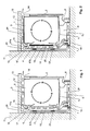
- Fig. 1 eine erste Ausführung eines Geschirrspülers und
- Fig. 2 eine zweite Ausführung eines Geschirrspülers.
- Der Geschirrspüler gemäss Fig. 1 besitzt einen Bottich 1 zur Aufnahme des zu reinigenden Geschirrs. Nach vorne wird der Bottich 1 von einer Türe 2 begrenzt. Die übrigen Aussenwände des Bottichs 1 werden von einer Deckwand 3, einer Rückwand 4, einem Boden 5 und nicht gezeigten Seitenwänden gebildet.
- Zur Aufnahme und Reinigung des Geschirrs besitzt der Geschirrspüler in üblicher Weise Geschirrkörbe, Sprüharme, Wasserpumpen, Heizaggregate, Rohre, Schläuche etc., welche der Einfachheit halber in den Figuren nicht dargestellt sind. Einige dieser Komponenten, insbesondere die Pumpen, sind in einem Raum 6 (dem Sockelraum) unter-halb des Bottichs 1 angeordnet.
- Ebenfalls im Raum 6 unterhalb des Bottichs ist ein Ventilator 7 angeordnet, dessen Aufgabe es ist, Kühlluft entlang mindestens einem Teil der Aussenwände des Bottichs 1 zu führen. Die Kühlluft dient dazu, die Aussenwände während der Trocknungsphase zu kühlen, so dass sich Wasser aus der Bottichluft an diesen niederschlägt. Dieses Wasser läuft an den Boden 5 des Bottichs, von wo es abgepumpt werden kann.
- In der vorliegenden Ausführung saugt der Ventilator 7 Umgebungsluft durch eine Spalte 8 unterhalb der der Türe 2 an. Diese wird durch einen Ansaugkanal 9 am Boden des Raums 6 zum Ventilator 7 geführt. Vom Ventilator 7 gelangt die Kühlluft zu einem rückseitigen Kanal 10, der z.B. zwischen der Rückwand 4 und einer hinter dem Geschirrspüler angeordneten Küchenwand 11 gebildet wird. Dort kühlt die Kühlluft die Rückwand 4. Sodann tritt die Kühlluft in einen oberen Kanal 12, der z.B. zwischen der Deckwand 3 und einer Abdeckplatte 13 gebildet wird, wo sie die Deckwand kühlt. Schliesslich tritt die Kühlluft durch einen Spalt 14 oberhalb der Türe 2 aus.
- Um den Kühleffekt zu erhöhen, ist im vorliegenden Beispiel die Rückwand 4 mit einer Oberflächenstruktur 15 versehen. Diese führt zu einer Verwirbelung der Kühlluft, was deren Kühlwirkung erhöht.
- Die Oberflächenstruktur 15 kann z.B. durch Prägen des Blechs der Rückwand 4 erzeugt werden, oder auch durch Anbringen separat gefertigter Rippen, Noppen oder ähnlicher Strukturen. Vorzugsweise verläuft mindestens ein Teil der Struktur quer zum Luftstrom, so dass die gewünschten Verwirbelungen begünstigt werden. Zusätzlich können auch Längsstrukturen, z.B. in Form klassischer Kühlrippen, vorgesehen sein.
- Im Beispiel nach Fig. 1 besitzt nur die Rückwand 1 eine solche Struktur 15. Alternativ oder zusätzlich hierzu können entsprechende Strukturen auch an anderen von der Kühlluft gekühlten Aussenseiten des Bottichs 1 vorgesehen sein.
- An der Rückseite des Geschirrspülers nach Fig. 1 ist ein Dampfabzug 16 angeordnet, der dazu dient, dem Bottich 1 mit Dampf angereicherte Luft zu entziehen. Dieser besitzt einen Luftkanal 17, mit welchem die Luft von einer Austrittsöffnung 18 in der Rückwand 4 des Bottichs 1 zu einem Unterdruckbereich 19 vor dem Ventilator 7 geführt werden kann. Der Luftkanal 17 besitzt einen ersten Abschnitt 17a und einen zweiten Abschnitt 17b. Die Luft von der Austrittsöffnung 18 gelangt zuerst in den ersten Abschnitt 17a, in welchem sie nach oben in einen höchsten Bereich 20 des Luftkanals 17 geführt wird. Kondensat, welches sich in diesem ersten Abschnitt 17a ablagert, kann somit durch die Austrittsöffnung 18 wieder zurück in den Bottich 1 laufen. Die auf diese Weise vorgetrocknete Luft durchläuft sodann den zweiten Abschnitt 17b, in welchem sie nach unten in den Unterdruckbereich 19 geführt wird. Dort wird sie mit der Kühlluft vermischt.
- Das Mischverhältnis zwischen der aus dem Bottich abgesogenen Luft und der Kühlluft wird z.B. auf 1:5 eingestellt.
- Um die durch die Austrittsöffnung 18 weggeförderte Luft zu ersetzen, ist in einem unteren Bereich der Rückwand 4 eine Eintrittsöffnung 23 zum Zuführen frischer Luft vorgesehen. Die Eintrittsöffnung 23 verbindet den Bottich mit dem Raum 6 unter dem Bottich 1. Diese Anordnung hat den Vorteil, dass die dem Bottich 1 zugeführte Luft von den im Raum 6 angeordneten Vorrichtungen, insbesondere Heizung und Pumpen, vorgewärmt werden kann. Optional kann die eintretende Luft mit einer geeigneten Heizung auch noch zusätzlich erwärmt werden.
- Wie aus Fig. 1 ersichtlich, ist die Austrittsöffnung 18 in einem oberen Bereich des Bottichs 1 angeordnet, während der Unterdruckbereich 19 tiefer liegt, im vorliegenden Beispiel unterhalb des Bottichs 1. Dies macht es erforderlich, die Abluft nach unten zu führen. Dadurch wird ein Kamineffekt, der Luft auch bei abgeschaltetem Ventilator 7 durch Eintrittsöffnung 23 und Austrittsöffnung 18 fördern würde, vermieden.
- Weiter ist der Ventilator 7 in einem rückseitigen Bereich des Geschirrspülers angeordnet. Dadurch wird für die Schalldämpfung der Luftwege viel Platz geschaffen.
- Vorzugsweise besitzt der Geschirrspüler eine Ventilatorsteuerung, mit welcher der Ventilator 7 mit mindestens zwei unterschiedlichen Förderleistungen grösser Null angesteuert werden kann. Die gewünschte Förderleistung kann vom Benutzer durch Betätigung der Bedienvorrichtung des Geschirrspülers ausgewählt werden. So kann die Förderleistung des Ventilators 7 für ein speziell ruhiges Programm reduziert bzw. für ein besonders schnelles Programm erhöht werden.
- In der Ausführung nach Fig. 1 werden die Aussenwände des Bottichs 1 von Blechen gebildet. In einer zweiten, in Fig. 2 dargestellten Ausführung, sind mindestens ein Teil der Aussenwände zusätzlich mit nicht-metallischen Schalldämmschichten 24, 25 versehen. Dabei handelt es sich um so genannte Schwerdämmfolien. Diese besitzen gute Schalldämmeigenschaften, aber dennoch eine relativ gute Wärmeleitfähigkeit, so dass die Kühlung der Bottichwände nicht beeinträchtigt wird. Schwerdämmfolien enthalten beispielsweise Teer oder Bitumen mit Zusätzen, z.B. Eisenoxid.
- In der Ausführung nach Fig. 2 wird die Kühlluft den Schalldämmschichten 24, 25 an der Rück- und Oberseite des Bottichs 1 entlang geführt. Zumindest die rückseitige Schalldämmschicht 24 ist an ihrer Aussenseite wiederum mit Strukturen 15 versehen, die zu einer Verwirbelung der Kühlluft führen. Die Strukturen können z.B. in die Oberfläche der Schalldämmschichten eingeprägt werden. Wird ein Thermoplast als Schalldämmsicht eingesetzt, so kann zur Schaffung der Strukturen z.B. eine Heissprägung eingesetzt werden.
- Die gezeigten Ausführungsbeispiele können in verschiedenster Weise variiert werden. Im Folgenden werden hierzu einige Beispiele genannt.
- In der Ausführung gemäss Fig. 1 und 2 befindet sich der Unterdruckbereich 19, in welchen die Luft vom Bottich gefördert wird, vor dem Ventilator 7. Alternativ hierzu kann auch eine Venturidüse oder dergleichen nach dem Ventilator eingesetzt werden.
- Das hier gezeigte Konzept erlaubt es, in einfacher Weise Geschirrspüler mit unterschiedlichen Konfortstufen anzubieten. In einer einfachsten Version können der Dampfabzug 16 und der Ventilator 7 weggelassen werden. Die Öffnung 18 wird geschlossen. In diesem Fall zieht aufgrund des Kamineffekts immer noch eine gewisse Menge von Raumluft an der Rückseite des Bottichs 1 nach oben und kühlt dessen Aussenwand. In einer verbesserten Version kann der Ventilator 7 auch ohne den Dampfabzug 16 verwendet werden.
Claims (11)
- Geschirrspüler gekennzeichnet durch einen Bottich (1),
mindestens einen Ventilator (7) zum Fördern von Kühlluft entlang mindestens einer Aussenwand (3, 4) des Bottichs (1) zum Kühlen der Aussenwand (3, 4) und
einen Dampfabzug (16), welcher eine Austrittsöffnung (18) im Bottich (1) mit einem Unterdruckbereich (19) verbindet, wobei mit dem Ventilator (7) im Unterdruckbereich (19) ein Unterdruck gegenüber dem Bottich (1) erzeugbar ist, derart, dass mit dem Ventilator (7) Luft aus dem Bottich (1) abziehbar ist. - Geschirrspüler nach Anspruch 1, wobei der Unterdruckbereich (19) unterhalb des Bottichs (1) angeordnet ist.
- Geschirrspüler nach einem der vorangehenden Ansprüche, wobei die Austrittsöffnung (18) höher als der Unterdruckbereich (19) angeordnet ist und der Dampfabzug (16) einen Luftkanal (17) von der Austrittsöffnung (18) zum Unterdruckbereich (19) aufweist.
- Geschirrspüler nach Anspruch 3, wobei der Luftkanal (17) von der Austrittsöffnung (18) in einem ersten Abschnitt (17a) nach oben in einen höchsten Bereich und vom höchsten Bereich sodann in einem zweiten Abschnitt (17b) nach unten läuft und derart ausgestaltet ist, dass mindestens ein Teil von im ersten Abschnitt entstandenem Kondensat durch die Austrittsöffnung (18) zurück in den Bottich (1) läuft.
- Geschirrspüler nach einem der vorangehenden Ansprüche, wobei die durch die Umgebungsluft gekühlte Aussenwand eine Oberflächenstruktur (15) zum Verwirbeln der Kühlluft aufweist.
- Geschirrspüler nach Anspruch 5, wobei die Oberflächenstruktur (15) mindestens teilweise quer zum Luftstrom der Kühlluft angeordnet ist.
- Geschirrspüler nach einem der vorangehenden Ansprüche mit einer nicht-metallischen Schalldämmschicht (24, 25) an mindestens einer Aussenwand, wobei der Ventilator (7) ausgestaltet ist um Umgebungsluft an einer Aussenseite der Schalldämmschicht entlang zu fördern, und insbesondere dass die Aussenseite eine Oberflächenstruktur (15) zum Verwirbeln der Kühlluft aufweist.
- Geschirrspüler nach Anspruch 7, wobei die Schalldämmschichten (24, 25) Schwerdämmfolien sind.
- Geschirrspüler nach einem der vorangehenden Ansprüche, wobei der Bottich (1) eine Eintrittsöffnung (23) zum Eintritt von Umgebungsluft in den Bottich (1) aufweist, und insbesondere wobei die Eintrittsöffnung (23) den Bottich (1) mit einem Raum (6) unter dem Bottich (1) verbindet, wobei im Raum (6) unter dem Bottich (1) mindestens eine Pumpe und/oder eine Heizung des Geschirrspülers angeordnet ist.
- Geschirrspüler nach einem der vorangehenden Ansprüche, wobei der Ventilator (7) in einem rückseitigen Bereich des Geschirrspülers angeordnet ist, und insbesondere wobei er zum Fördern von Kühlluft entlang einer Rückseite des Bottichs (1) ausgestaltet ist.
- Geschirrspüler nach einem der vorangehenden Ansprüche mit einer Ventilatorsteuerung, mit welcher der Ventilator (7) mit mindestens zwei unterschiedlichen Förderleistungen grösser Null ansteuerbar ist, wobei die jeweilige Förderleistung vom Benutzer durch Betätigung einer Bedienvorrichtung des Geschirrspülers wählbar ist.
Priority Applications (2)
| Application Number | Priority Date | Filing Date | Title |
|---|---|---|---|
| SI200631616T SI1825800T1 (sl) | 2006-02-22 | 2006-08-10 | Pomivalni stroj s sredstvom za odvod vlage iz kadi |
| PL06016685T PL1825800T3 (pl) | 2006-02-22 | 2006-08-10 | Zmywarka do naczyń ze środkami do odciągania wilgoci ze zbiornika |
Applications Claiming Priority (1)
| Application Number | Priority Date | Filing Date | Title |
|---|---|---|---|
| CH2752006 | 2006-02-22 |
Publications (3)
| Publication Number | Publication Date |
|---|---|
| EP1825800A2 true EP1825800A2 (de) | 2007-08-29 |
| EP1825800A3 EP1825800A3 (de) | 2008-05-14 |
| EP1825800B1 EP1825800B1 (de) | 2013-04-17 |
Family
ID=38217599
Family Applications (1)
| Application Number | Title | Priority Date | Filing Date |
|---|---|---|---|
| EP06016685.7A Expired - Lifetime EP1825800B1 (de) | 2006-02-22 | 2006-08-10 | Geschirrspüler mit Mitteln zum Abziehen von Feuchte aus dem Bottich |
Country Status (4)
| Country | Link |
|---|---|
| EP (1) | EP1825800B1 (de) |
| DK (1) | DK1825800T3 (de) |
| PL (1) | PL1825800T3 (de) |
| SI (1) | SI1825800T1 (de) |
Cited By (16)
| Publication number | Priority date | Publication date | Assignee | Title |
|---|---|---|---|---|
| WO2009021603A1 (de) * | 2007-08-13 | 2009-02-19 | Miele & Cie. Kg | Geschirrspüler mit mittel zum verändern der wärmeabstrahlung |
| EP2371258A3 (de) * | 2011-06-06 | 2012-03-07 | V-Zug AG | Geschirrspüler mit Türspaltlüftung |
| EP2586357A1 (de) * | 2011-10-28 | 2013-05-01 | Bitron S.p.A. | Trocknungssystem für eine Geschirrspülmaschine |
| CN103156563A (zh) * | 2011-12-14 | 2013-06-19 | 松下电器产业株式会社 | 餐具清洗机 |
| EP2636357A1 (de) * | 2012-03-06 | 2013-09-11 | Miele & Cie. KG | Spülmaschine, insbesondere Haushaltsgeschirrspülmaschine |
| EP2682038A2 (de) * | 2012-07-03 | 2014-01-08 | Miele & Cie. KG | Geschirrspülmaschine und Verfahren zum Betreiben einer Geschirrspülmaschine |
| WO2014005857A3 (de) * | 2012-07-04 | 2014-06-26 | BSH Bosch und Siemens Hausgeräte GmbH | Geschirrspülmaschine, insbesondere haushaltsgeschirr-spülmaschine, mit wenigstens einer leitstruktur an ihrer türinnenseite zum umlenken von dort entlang strömenden trocknungsfluid |
| US20140223761A1 (en) * | 2013-02-12 | 2014-08-14 | Lg Electronics Inc. | Dishwasher and method of controlling the same |
| KR20140101632A (ko) * | 2013-02-12 | 2014-08-20 | 엘지전자 주식회사 | 식기세척기 및 그 제어방법 |
| KR20140101631A (ko) * | 2013-02-12 | 2014-08-20 | 엘지전자 주식회사 | 식기세척기 및 그 제어방법 |
| WO2014180648A1 (en) * | 2013-05-06 | 2014-11-13 | Arcelik Anonim Sirketi | A dishwasher with improved drying performance |
| US9510728B2 (en) | 2014-11-20 | 2016-12-06 | Whilrpool Corporation | Reduced vapor dry systems and methods for dishwashers |
| EP3213666A1 (de) * | 2016-03-04 | 2017-09-06 | Miele & Cie. KG | Geschirrspülmaschine |
| EP3257425A4 (de) * | 2015-02-12 | 2018-03-14 | Foshan Shunde Midea Washing Appliances Mfg. Co., Ltd. | Geschirrspülmaschine |
| EP3597096A1 (de) * | 2018-07-20 | 2020-01-22 | Miele & Cie. KG | Verfahren zur durchführung eines trocknungs-programmabschnitts in einer geschirrspülmaschine und geschirrspülmaschine zur durchführung des verfahrens |
| US12318054B2 (en) | 2018-09-20 | 2025-06-03 | Electrolux Appliances Aktiebolag | Dishwasher goods drying system |
Families Citing this family (1)
| Publication number | Priority date | Publication date | Assignee | Title |
|---|---|---|---|---|
| KR20240050938A (ko) * | 2022-10-12 | 2024-04-19 | 삼성전자주식회사 | 식기세척기 및 식기세척기의 제어 방법 |
Citations (1)
| Publication number | Priority date | Publication date | Assignee | Title |
|---|---|---|---|---|
| DE9106598U1 (de) | 1991-05-29 | 1991-08-14 | Bauknecht Hausgeräte GmbH, 7000 Stuttgart | Haushaltgerät, z.B. Geschirrspüler, mit einem Gebläse |
Family Cites Families (4)
| Publication number | Priority date | Publication date | Assignee | Title |
|---|---|---|---|---|
| DE4037367C2 (de) * | 1990-11-23 | 1994-03-31 | Bosch Siemens Hausgeraete | Anordnung zum Trocknen von Geschirr in Geschirrspülmaschinen |
| JPH05211978A (ja) * | 1992-02-05 | 1993-08-24 | Toshiba Corp | 食器乾燥機 |
| IT1303213B1 (it) * | 1998-08-06 | 2000-11-02 | Bitron Spa | Dispositivo per l'asciugatura delle stoviglie al termine del processodi lavaggio di una lavastoviglie |
| DE10346964B4 (de) * | 2003-10-09 | 2019-09-26 | BSH Hausgeräte GmbH | Geschirrspüler mit variabler Wärmedämmung |
-
2006
- 2006-08-10 PL PL06016685T patent/PL1825800T3/pl unknown
- 2006-08-10 DK DK06016685.7T patent/DK1825800T3/da active
- 2006-08-10 SI SI200631616T patent/SI1825800T1/sl unknown
- 2006-08-10 EP EP06016685.7A patent/EP1825800B1/de not_active Expired - Lifetime
Patent Citations (1)
| Publication number | Priority date | Publication date | Assignee | Title |
|---|---|---|---|---|
| DE9106598U1 (de) | 1991-05-29 | 1991-08-14 | Bauknecht Hausgeräte GmbH, 7000 Stuttgart | Haushaltgerät, z.B. Geschirrspüler, mit einem Gebläse |
Cited By (24)
| Publication number | Priority date | Publication date | Assignee | Title |
|---|---|---|---|---|
| US8616225B2 (en) | 2007-08-13 | 2013-12-31 | Miele & Cie. Kg | Dishwasher having means for changing heat dissipation |
| WO2009021603A1 (de) * | 2007-08-13 | 2009-02-19 | Miele & Cie. Kg | Geschirrspüler mit mittel zum verändern der wärmeabstrahlung |
| EP2371258A3 (de) * | 2011-06-06 | 2012-03-07 | V-Zug AG | Geschirrspüler mit Türspaltlüftung |
| CN102813494A (zh) * | 2011-06-06 | 2012-12-12 | V-楚格股份公司 | 通过门框处的间隙通风的洗碗机 |
| AU2012203276B2 (en) * | 2011-06-06 | 2016-08-18 | V-Zug Ag | Dishwasher vented through clearance at door frames |
| EP2586357A1 (de) * | 2011-10-28 | 2013-05-01 | Bitron S.p.A. | Trocknungssystem für eine Geschirrspülmaschine |
| CN103156563A (zh) * | 2011-12-14 | 2013-06-19 | 松下电器产业株式会社 | 餐具清洗机 |
| CN103156563B (zh) * | 2011-12-14 | 2015-01-28 | 松下电器产业株式会社 | 餐具清洗机 |
| EP2636357A1 (de) * | 2012-03-06 | 2013-09-11 | Miele & Cie. KG | Spülmaschine, insbesondere Haushaltsgeschirrspülmaschine |
| EP2682038A2 (de) * | 2012-07-03 | 2014-01-08 | Miele & Cie. KG | Geschirrspülmaschine und Verfahren zum Betreiben einer Geschirrspülmaschine |
| WO2014005857A3 (de) * | 2012-07-04 | 2014-06-26 | BSH Bosch und Siemens Hausgeräte GmbH | Geschirrspülmaschine, insbesondere haushaltsgeschirr-spülmaschine, mit wenigstens einer leitstruktur an ihrer türinnenseite zum umlenken von dort entlang strömenden trocknungsfluid |
| CN104582556A (zh) * | 2012-07-04 | 2015-04-29 | Bsh博世和西门子家用电器有限公司 | 在门的内表面上包括使沿着门内表面流动的干燥流体偏向的至少一个引导结构的洗碗机、特别是家用洗碗机 |
| US20140223761A1 (en) * | 2013-02-12 | 2014-08-14 | Lg Electronics Inc. | Dishwasher and method of controlling the same |
| KR20140101632A (ko) * | 2013-02-12 | 2014-08-20 | 엘지전자 주식회사 | 식기세척기 및 그 제어방법 |
| KR20140101631A (ko) * | 2013-02-12 | 2014-08-20 | 엘지전자 주식회사 | 식기세척기 및 그 제어방법 |
| US9635997B2 (en) * | 2013-02-12 | 2017-05-02 | Lg Electronics Inc. | Dishwasher and method of controlling the same |
| WO2014180648A1 (en) * | 2013-05-06 | 2014-11-13 | Arcelik Anonim Sirketi | A dishwasher with improved drying performance |
| US9763555B2 (en) | 2013-05-06 | 2017-09-19 | Arcelik Anonim Sirketi | Dishwasher with improved drying performance |
| US9510728B2 (en) | 2014-11-20 | 2016-12-06 | Whilrpool Corporation | Reduced vapor dry systems and methods for dishwashers |
| EP3257425A4 (de) * | 2015-02-12 | 2018-03-14 | Foshan Shunde Midea Washing Appliances Mfg. Co., Ltd. | Geschirrspülmaschine |
| EP3213666A1 (de) * | 2016-03-04 | 2017-09-06 | Miele & Cie. KG | Geschirrspülmaschine |
| DE102016103921A1 (de) * | 2016-03-04 | 2017-09-07 | Miele & Cie. Kg | Geschirrspülmaschine |
| EP3597096A1 (de) * | 2018-07-20 | 2020-01-22 | Miele & Cie. KG | Verfahren zur durchführung eines trocknungs-programmabschnitts in einer geschirrspülmaschine und geschirrspülmaschine zur durchführung des verfahrens |
| US12318054B2 (en) | 2018-09-20 | 2025-06-03 | Electrolux Appliances Aktiebolag | Dishwasher goods drying system |
Also Published As
| Publication number | Publication date |
|---|---|
| DK1825800T3 (da) | 2013-05-06 |
| PL1825800T3 (pl) | 2013-08-30 |
| SI1825800T1 (sl) | 2013-08-30 |
| EP1825800B1 (de) | 2013-04-17 |
| EP1825800A3 (de) | 2008-05-14 |
Similar Documents
| Publication | Publication Date | Title |
|---|---|---|
| EP1825800B1 (de) | Geschirrspüler mit Mitteln zum Abziehen von Feuchte aus dem Bottich | |
| EP2371258A2 (de) | Geschirrspüler mit Türspaltlüftung | |
| EP2802820B1 (de) | Dampfgarbackofen mit beheizbarer wasserschale | |
| CH682512A5 (de) | Dampfabzugeinrichtung. | |
| EP0190794A2 (de) | Einbau-Kühlschrank | |
| EP3701192A1 (de) | Kombinationsgerät mit dunstabzugsvorrichtung und kochfeld | |
| EP3710756A1 (de) | Dunstabzugsvorrichtung für ein kochfeld und küchenmöbel mit dunstabzugsvorrichtung | |
| EP2462808B1 (de) | Dampfgargerät | |
| CH704954B1 (de) | Dunstabzugshaube zur Anordnung über einer Kochstelle. | |
| DE102017216456A1 (de) | Lüftungsvorrichtung für Kochfeld und Kochfeld mit Lüftungsvorrichtung | |
| DE202020100040U1 (de) | Ansaugvorrichtung für eine Dunstabzugshaube für Privathaushalte | |
| DE20317601U1 (de) | Kondensationsvorrichtung für die Abluft eines Gargerätes | |
| DE102019100002A1 (de) | Anordnung einer Geschirrspülmaschine mit Wärmepumpenkreislauf und Unterbauzubehör | |
| EP3341518B1 (de) | Haushaltsgerät mit abreinigungseinrichtung für wärmetauscher | |
| EP0920830B1 (de) | Verfahren zur Geschirrtrocknung in einer elekrischen Haushaltsmaschine | |
| DE4135130C2 (de) | Be- und Entlüftungssystem für Wohnräume in Wohnungen | |
| DE102011106368A1 (de) | Vorrichtung zum Absaugen von Gasen und/oder Rauch | |
| DE102015010472A1 (de) | Duschanordnung | |
| EP2677242B1 (de) | Vorrichtung zum ableiten von luft | |
| EP1833351B1 (de) | Geschirrspülmaschine mit einer trocknungsvorrichtung | |
| EP1838204A1 (de) | Geschirrspülmaschine mit einer trocknungsvorrichtung | |
| EP2462809B1 (de) | Dampfgargerät | |
| EP1094278A2 (de) | Dunstabzugsvorrichtung | |
| EP4328495A1 (de) | In ein kochfeld baulich integrierbare dunstabzugsvorrichtung und kochfeld | |
| DE102007030573B4 (de) | Gargerät mit zumindest einer Kondensationseinrichtung und Verfahren zum Entfeuchten eines Garraums solch eines Gargeräts |
Legal Events
| Date | Code | Title | Description |
|---|---|---|---|
| PUAI | Public reference made under article 153(3) epc to a published international application that has entered the european phase |
Free format text: ORIGINAL CODE: 0009012 |
|
| AK | Designated contracting states |
Kind code of ref document: A2 Designated state(s): AT BE BG CH CY CZ DE DK EE ES FI FR GB GR HU IE IS IT LI LT LU LV MC NL PL PT RO SE SI SK TR |
|
| AX | Request for extension of the european patent |
Extension state: AL BA HR MK YU |
|
| PUAL | Search report despatched |
Free format text: ORIGINAL CODE: 0009013 |
|
| AK | Designated contracting states |
Kind code of ref document: A3 Designated state(s): AT BE BG CH CY CZ DE DK EE ES FI FR GB GR HU IE IS IT LI LT LU LV MC NL PL PT RO SE SI SK TR |
|
| AX | Request for extension of the european patent |
Extension state: AL BA HR MK RS |
|
| 17P | Request for examination filed |
Effective date: 20081111 |
|
| AKX | Designation fees paid |
Designated state(s): AT BE BG CH CY CZ DE DK EE ES FI FR GB GR HU IE IS IT LI LT LU LV MC NL PL PT RO SE SI SK TR |
|
| GRAP | Despatch of communication of intention to grant a patent |
Free format text: ORIGINAL CODE: EPIDOSNIGR1 |
|
| GRAS | Grant fee paid |
Free format text: ORIGINAL CODE: EPIDOSNIGR3 |
|
| GRAA | (expected) grant |
Free format text: ORIGINAL CODE: 0009210 |
|
| AK | Designated contracting states |
Kind code of ref document: B1 Designated state(s): AT BE BG CH CY CZ DE DK EE ES FI FR GB GR HU IE IS IT LI LT LU LV MC NL PL PT RO SE SI SK TR |
|
| REG | Reference to a national code |
Ref country code: GB Ref legal event code: FG4D Free format text: NOT ENGLISH |
|
| REG | Reference to a national code |
Ref country code: CH Ref legal event code: NV Representative=s name: E. BLUM AND CO. AG PATENT- UND MARKENANWAELTE , CH Ref country code: CH Ref legal event code: EP |
|
| REG | Reference to a national code |
Ref country code: DK Ref legal event code: T3 |
|
| REG | Reference to a national code |
Ref country code: IE Ref legal event code: FG4D Free format text: LANGUAGE OF EP DOCUMENT: GERMAN |
|
| REG | Reference to a national code |
Ref country code: AT Ref legal event code: REF Ref document number: 606735 Country of ref document: AT Kind code of ref document: T Effective date: 20130515 |
|
| REG | Reference to a national code |
Ref country code: DE Ref legal event code: R096 Ref document number: 502006012732 Country of ref document: DE Effective date: 20130613 |
|
| REG | Reference to a national code |
Ref country code: SE Ref legal event code: TRGR |
|
| REG | Reference to a national code |
Ref country code: NL Ref legal event code: T3 |
|
| REG | Reference to a national code |
Ref country code: PL Ref legal event code: T3 |
|
| REG | Reference to a national code |
Ref country code: LT Ref legal event code: MG4D |
|
| PG25 | Lapsed in a contracting state [announced via postgrant information from national office to epo] |
Ref country code: LT Free format text: LAPSE BECAUSE OF FAILURE TO SUBMIT A TRANSLATION OF THE DESCRIPTION OR TO PAY THE FEE WITHIN THE PRESCRIBED TIME-LIMIT Effective date: 20130417 Ref country code: FI Free format text: LAPSE BECAUSE OF FAILURE TO SUBMIT A TRANSLATION OF THE DESCRIPTION OR TO PAY THE FEE WITHIN THE PRESCRIBED TIME-LIMIT Effective date: 20130417 Ref country code: PT Free format text: LAPSE BECAUSE OF FAILURE TO SUBMIT A TRANSLATION OF THE DESCRIPTION OR TO PAY THE FEE WITHIN THE PRESCRIBED TIME-LIMIT Effective date: 20130819 Ref country code: ES Free format text: LAPSE BECAUSE OF FAILURE TO SUBMIT A TRANSLATION OF THE DESCRIPTION OR TO PAY THE FEE WITHIN THE PRESCRIBED TIME-LIMIT Effective date: 20130728 Ref country code: GR Free format text: LAPSE BECAUSE OF FAILURE TO SUBMIT A TRANSLATION OF THE DESCRIPTION OR TO PAY THE FEE WITHIN THE PRESCRIBED TIME-LIMIT Effective date: 20130718 Ref country code: IS Free format text: LAPSE BECAUSE OF FAILURE TO SUBMIT A TRANSLATION OF THE DESCRIPTION OR TO PAY THE FEE WITHIN THE PRESCRIBED TIME-LIMIT Effective date: 20130817 |
|
| PG25 | Lapsed in a contracting state [announced via postgrant information from national office to epo] |
Ref country code: BG Free format text: LAPSE BECAUSE OF FAILURE TO SUBMIT A TRANSLATION OF THE DESCRIPTION OR TO PAY THE FEE WITHIN THE PRESCRIBED TIME-LIMIT Effective date: 20130717 Ref country code: LV Free format text: LAPSE BECAUSE OF FAILURE TO SUBMIT A TRANSLATION OF THE DESCRIPTION OR TO PAY THE FEE WITHIN THE PRESCRIBED TIME-LIMIT Effective date: 20130417 Ref country code: CY Free format text: LAPSE BECAUSE OF FAILURE TO SUBMIT A TRANSLATION OF THE DESCRIPTION OR TO PAY THE FEE WITHIN THE PRESCRIBED TIME-LIMIT Effective date: 20130417 |
|
| PG25 | Lapsed in a contracting state [announced via postgrant information from national office to epo] |
Ref country code: SK Free format text: LAPSE BECAUSE OF FAILURE TO SUBMIT A TRANSLATION OF THE DESCRIPTION OR TO PAY THE FEE WITHIN THE PRESCRIBED TIME-LIMIT Effective date: 20130417 Ref country code: CZ Free format text: LAPSE BECAUSE OF FAILURE TO SUBMIT A TRANSLATION OF THE DESCRIPTION OR TO PAY THE FEE WITHIN THE PRESCRIBED TIME-LIMIT Effective date: 20130417 Ref country code: EE Free format text: LAPSE BECAUSE OF FAILURE TO SUBMIT A TRANSLATION OF THE DESCRIPTION OR TO PAY THE FEE WITHIN THE PRESCRIBED TIME-LIMIT Effective date: 20130417 |
|
| PLBE | No opposition filed within time limit |
Free format text: ORIGINAL CODE: 0009261 |
|
| STAA | Information on the status of an ep patent application or granted ep patent |
Free format text: STATUS: NO OPPOSITION FILED WITHIN TIME LIMIT |
|
| BERE | Be: lapsed |
Owner name: V-ZUG A.G. Effective date: 20130831 |
|
| PG25 | Lapsed in a contracting state [announced via postgrant information from national office to epo] |
Ref country code: RO Free format text: LAPSE BECAUSE OF FAILURE TO SUBMIT A TRANSLATION OF THE DESCRIPTION OR TO PAY THE FEE WITHIN THE PRESCRIBED TIME-LIMIT Effective date: 20130417 |
|
| 26N | No opposition filed |
Effective date: 20140120 |
|
| PG25 | Lapsed in a contracting state [announced via postgrant information from national office to epo] |
Ref country code: MC Free format text: LAPSE BECAUSE OF FAILURE TO SUBMIT A TRANSLATION OF THE DESCRIPTION OR TO PAY THE FEE WITHIN THE PRESCRIBED TIME-LIMIT Effective date: 20130417 |
|
| REG | Reference to a national code |
Ref country code: DE Ref legal event code: R097 Ref document number: 502006012732 Country of ref document: DE Effective date: 20140120 |
|
| REG | Reference to a national code |
Ref country code: IE Ref legal event code: MM4A |
|
| PG25 | Lapsed in a contracting state [announced via postgrant information from national office to epo] |
Ref country code: BE Free format text: LAPSE BECAUSE OF NON-PAYMENT OF DUE FEES Effective date: 20130831 |
|
| PG25 | Lapsed in a contracting state [announced via postgrant information from national office to epo] |
Ref country code: IE Free format text: LAPSE BECAUSE OF NON-PAYMENT OF DUE FEES Effective date: 20130810 |
|
| REG | Reference to a national code |
Ref country code: AT Ref legal event code: MM01 Ref document number: 606735 Country of ref document: AT Kind code of ref document: T Effective date: 20130810 |
|
| PG25 | Lapsed in a contracting state [announced via postgrant information from national office to epo] |
Ref country code: AT Free format text: LAPSE BECAUSE OF NON-PAYMENT OF DUE FEES Effective date: 20130810 |
|
| PG25 | Lapsed in a contracting state [announced via postgrant information from national office to epo] |
Ref country code: TR Free format text: LAPSE BECAUSE OF FAILURE TO SUBMIT A TRANSLATION OF THE DESCRIPTION OR TO PAY THE FEE WITHIN THE PRESCRIBED TIME-LIMIT Effective date: 20130417 |
|
| PG25 | Lapsed in a contracting state [announced via postgrant information from national office to epo] |
Ref country code: LU Free format text: LAPSE BECAUSE OF NON-PAYMENT OF DUE FEES Effective date: 20130810 Ref country code: HU Free format text: LAPSE BECAUSE OF FAILURE TO SUBMIT A TRANSLATION OF THE DESCRIPTION OR TO PAY THE FEE WITHIN THE PRESCRIBED TIME-LIMIT; INVALID AB INITIO Effective date: 20060810 |
|
| REG | Reference to a national code |
Ref country code: FR Ref legal event code: PLFP Year of fee payment: 11 |
|
| REG | Reference to a national code |
Ref country code: DE Ref legal event code: R082 Ref document number: 502006012732 Country of ref document: DE Representative=s name: KLUNKER IP PATENTANWAELTE PARTG MBB, DE |
|
| REG | Reference to a national code |
Ref country code: FR Ref legal event code: PLFP Year of fee payment: 12 |
|
| REG | Reference to a national code |
Ref country code: SI Ref legal event code: SP73 Owner name: V-ZUG AG; CH Effective date: 20180628 |
|
| REG | Reference to a national code |
Ref country code: FR Ref legal event code: PLFP Year of fee payment: 13 |
|
| PGFP | Annual fee paid to national office [announced via postgrant information from national office to epo] |
Ref country code: DE Payment date: 20180823 Year of fee payment: 13 Ref country code: FR Payment date: 20180827 Year of fee payment: 13 Ref country code: NL Payment date: 20180821 Year of fee payment: 13 Ref country code: IT Payment date: 20180830 Year of fee payment: 13 |
|
| PGFP | Annual fee paid to national office [announced via postgrant information from national office to epo] |
Ref country code: SE Payment date: 20180731 Year of fee payment: 13 Ref country code: GB Payment date: 20180822 Year of fee payment: 13 Ref country code: SE Payment date: 20180823 Year of fee payment: 13 Ref country code: SI Payment date: 20180723 Year of fee payment: 13 Ref country code: PL Payment date: 20180719 Year of fee payment: 13 |
|
| REG | Reference to a national code |
Ref country code: DE Ref legal event code: R119 Ref document number: 502006012732 Country of ref document: DE |
|
| REG | Reference to a national code |
Ref country code: DK Ref legal event code: EBP Effective date: 20190831 |
|
| REG | Reference to a national code |
Ref country code: NL Ref legal event code: MM Effective date: 20190901 |
|
| REG | Reference to a national code |
Ref country code: SE Ref legal event code: EUG |
|
| GBPC | Gb: european patent ceased through non-payment of renewal fee |
Effective date: 20190810 |
|
| PG25 | Lapsed in a contracting state [announced via postgrant information from national office to epo] |
Ref country code: SE Free format text: LAPSE BECAUSE OF NON-PAYMENT OF DUE FEES Effective date: 20190811 |
|
| PG25 | Lapsed in a contracting state [announced via postgrant information from national office to epo] |
Ref country code: FR Free format text: LAPSE BECAUSE OF NON-PAYMENT OF DUE FEES Effective date: 20190831 Ref country code: DE Free format text: LAPSE BECAUSE OF NON-PAYMENT OF DUE FEES Effective date: 20200303 Ref country code: NL Free format text: LAPSE BECAUSE OF NON-PAYMENT OF DUE FEES Effective date: 20190901 Ref country code: DK Free format text: LAPSE BECAUSE OF NON-PAYMENT OF DUE FEES Effective date: 20190831 |
|
| PG25 | Lapsed in a contracting state [announced via postgrant information from national office to epo] |
Ref country code: IT Free format text: LAPSE BECAUSE OF NON-PAYMENT OF DUE FEES Effective date: 20190810 Ref country code: SI Free format text: LAPSE BECAUSE OF NON-PAYMENT OF DUE FEES Effective date: 20190811 Ref country code: GB Free format text: LAPSE BECAUSE OF NON-PAYMENT OF DUE FEES Effective date: 20190810 |
|
| REG | Reference to a national code |
Ref country code: SI Ref legal event code: KO00 Effective date: 20180628 |
|
| PG25 | Lapsed in a contracting state [announced via postgrant information from national office to epo] |
Ref country code: PL Free format text: LAPSE BECAUSE OF NON-PAYMENT OF DUE FEES Effective date: 20190810 |
|
| PGFP | Annual fee paid to national office [announced via postgrant information from national office to epo] |
Ref country code: CH Payment date: 20250901 Year of fee payment: 20 |
|
| REG | Reference to a national code |
Ref country code: CH Ref legal event code: H14 Free format text: ST27 STATUS EVENT CODE: U-0-0-H10-H14 (AS PROVIDED BY THE NATIONAL OFFICE) Effective date: 20260810 |