EP1825822B1 - Dichtung für einen prothetischen vaskulären Stent - Google Patents
Dichtung für einen prothetischen vaskulären Stent Download PDFInfo
- Publication number
- EP1825822B1 EP1825822B1 EP06256633A EP06256633A EP1825822B1 EP 1825822 B1 EP1825822 B1 EP 1825822B1 EP 06256633 A EP06256633 A EP 06256633A EP 06256633 A EP06256633 A EP 06256633A EP 1825822 B1 EP1825822 B1 EP 1825822B1
- Authority
- EP
- European Patent Office
- Prior art keywords
- sealing gasket
- stent segment
- bracket
- stent
- framing
- Prior art date
- Legal status (The legal status is an assumption and is not a legal conclusion. Google has not performed a legal analysis and makes no representation as to the accuracy of the status listed.)
- Not-in-force
Links
Images
Classifications
-
- A—HUMAN NECESSITIES
- A61—MEDICAL OR VETERINARY SCIENCE; HYGIENE
- A61F—FILTERS IMPLANTABLE INTO BLOOD VESSELS; PROSTHESES; DEVICES PROVIDING PATENCY TO, OR PREVENTING COLLAPSING OF, TUBULAR STRUCTURES OF THE BODY, e.g. STENTS; ORTHOPAEDIC, NURSING OR CONTRACEPTIVE DEVICES; FOMENTATION; TREATMENT OR PROTECTION OF EYES OR EARS; BANDAGES, DRESSINGS OR ABSORBENT PADS; FIRST-AID KITS
- A61F2/00—Filters implantable into blood vessels; Prostheses, i.e. artificial substitutes or replacements for parts of the body; Appliances for connecting them with the body; Devices providing patency to, or preventing collapsing of, tubular structures of the body, e.g. stents
- A61F2/02—Prostheses implantable into the body
- A61F2/04—Hollow or tubular parts of organs, e.g. bladders, tracheae, bronchi or bile ducts
- A61F2/06—Blood vessels
- A61F2/07—Stent-grafts
-
- A—HUMAN NECESSITIES
- A61—MEDICAL OR VETERINARY SCIENCE; HYGIENE
- A61F—FILTERS IMPLANTABLE INTO BLOOD VESSELS; PROSTHESES; DEVICES PROVIDING PATENCY TO, OR PREVENTING COLLAPSING OF, TUBULAR STRUCTURES OF THE BODY, e.g. STENTS; ORTHOPAEDIC, NURSING OR CONTRACEPTIVE DEVICES; FOMENTATION; TREATMENT OR PROTECTION OF EYES OR EARS; BANDAGES, DRESSINGS OR ABSORBENT PADS; FIRST-AID KITS
- A61F2/00—Filters implantable into blood vessels; Prostheses, i.e. artificial substitutes or replacements for parts of the body; Appliances for connecting them with the body; Devices providing patency to, or preventing collapsing of, tubular structures of the body, e.g. stents
- A61F2/82—Devices providing patency to, or preventing collapsing of, tubular structures of the body, e.g. stents
- A61F2/86—Stents in a form characterised by the wire-like elements; Stents in the form characterised by a net-like or mesh-like structure
- A61F2/89—Stents in a form characterised by the wire-like elements; Stents in the form characterised by a net-like or mesh-like structure the wire-like elements comprising two or more adjacent rings flexibly connected by separate members
-
- A—HUMAN NECESSITIES
- A61—MEDICAL OR VETERINARY SCIENCE; HYGIENE
- A61F—FILTERS IMPLANTABLE INTO BLOOD VESSELS; PROSTHESES; DEVICES PROVIDING PATENCY TO, OR PREVENTING COLLAPSING OF, TUBULAR STRUCTURES OF THE BODY, e.g. STENTS; ORTHOPAEDIC, NURSING OR CONTRACEPTIVE DEVICES; FOMENTATION; TREATMENT OR PROTECTION OF EYES OR EARS; BANDAGES, DRESSINGS OR ABSORBENT PADS; FIRST-AID KITS
- A61F2/00—Filters implantable into blood vessels; Prostheses, i.e. artificial substitutes or replacements for parts of the body; Appliances for connecting them with the body; Devices providing patency to, or preventing collapsing of, tubular structures of the body, e.g. stents
- A61F2/82—Devices providing patency to, or preventing collapsing of, tubular structures of the body, e.g. stents
- A61F2/86—Stents in a form characterised by the wire-like elements; Stents in the form characterised by a net-like or mesh-like structure
- A61F2/90—Stents in a form characterised by the wire-like elements; Stents in the form characterised by a net-like or mesh-like structure characterised by a net-like or mesh-like structure
-
- A—HUMAN NECESSITIES
- A61—MEDICAL OR VETERINARY SCIENCE; HYGIENE
- A61F—FILTERS IMPLANTABLE INTO BLOOD VESSELS; PROSTHESES; DEVICES PROVIDING PATENCY TO, OR PREVENTING COLLAPSING OF, TUBULAR STRUCTURES OF THE BODY, e.g. STENTS; ORTHOPAEDIC, NURSING OR CONTRACEPTIVE DEVICES; FOMENTATION; TREATMENT OR PROTECTION OF EYES OR EARS; BANDAGES, DRESSINGS OR ABSORBENT PADS; FIRST-AID KITS
- A61F2/00—Filters implantable into blood vessels; Prostheses, i.e. artificial substitutes or replacements for parts of the body; Appliances for connecting them with the body; Devices providing patency to, or preventing collapsing of, tubular structures of the body, e.g. stents
- A61F2/02—Prostheses implantable into the body
- A61F2/04—Hollow or tubular parts of organs, e.g. bladders, tracheae, bronchi or bile ducts
- A61F2/06—Blood vessels
- A61F2/07—Stent-grafts
- A61F2002/075—Stent-grafts the stent being loosely attached to the graft material, e.g. by stitching
-
- A—HUMAN NECESSITIES
- A61—MEDICAL OR VETERINARY SCIENCE; HYGIENE
- A61F—FILTERS IMPLANTABLE INTO BLOOD VESSELS; PROSTHESES; DEVICES PROVIDING PATENCY TO, OR PREVENTING COLLAPSING OF, TUBULAR STRUCTURES OF THE BODY, e.g. STENTS; ORTHOPAEDIC, NURSING OR CONTRACEPTIVE DEVICES; FOMENTATION; TREATMENT OR PROTECTION OF EYES OR EARS; BANDAGES, DRESSINGS OR ABSORBENT PADS; FIRST-AID KITS
- A61F2230/00—Geometry of prostheses classified in groups A61F2/00 - A61F2/26 or A61F2/82 or A61F9/00 or A61F11/00 or subgroups thereof
- A61F2230/0063—Three-dimensional shapes
- A61F2230/0073—Quadric-shaped
- A61F2230/0078—Quadric-shaped hyperboloidal
-
- A—HUMAN NECESSITIES
- A61—MEDICAL OR VETERINARY SCIENCE; HYGIENE
- A61F—FILTERS IMPLANTABLE INTO BLOOD VESSELS; PROSTHESES; DEVICES PROVIDING PATENCY TO, OR PREVENTING COLLAPSING OF, TUBULAR STRUCTURES OF THE BODY, e.g. STENTS; ORTHOPAEDIC, NURSING OR CONTRACEPTIVE DEVICES; FOMENTATION; TREATMENT OR PROTECTION OF EYES OR EARS; BANDAGES, DRESSINGS OR ABSORBENT PADS; FIRST-AID KITS
- A61F2250/00—Special features of prostheses classified in groups A61F2/00 - A61F2/26 or A61F2/82 or A61F9/00 or A61F11/00 or subgroups thereof
- A61F2250/0058—Additional features; Implant or prostheses properties not otherwise provided for
- A61F2250/0069—Sealing means
Definitions
- the invention relates to the field of medical devices, and more specifically to a prosthesis for the treatment of vascular disease, particularly abdominal aortic aneurysm.
- Vascular disease is a leading cause of premature mortality in developed countries, often presenting as a vascular aneurysm.
- a vascular aneurysm is a localized dilation of a vessel wall, due to thinning or weakness of the wall structure, or separation between layers of the vessel wall. If untreated, the aneurysm may burst and hemorrhage uncontrollably.
- Aneurysms are particularly dangerous and prevalent in the aorta, because the aorta supplies blood to all other areas of the body, and because the aorta is subject to particularly high pressures and stresses accordingly.
- Rupture of an aortic aneurysm is the 15 th leading cause of death in the United States, afflicting 5% of older men.
- Aortic aneurysms are described by their position. They are either thoracic, generally between the aortic arch and the junction of the left and right renal arteries, or abdominal, between the junction of the renal arteries and the branch of the iliac arteries.
- vascular aneurysms surgically where blood pressure control medication is unsuccessful at arresting growth of the aneurysm.
- Surgery often involves the insertion of a vascular stent graft to exclude the aneurysm and carry blood past the dilated portion of the vessel, relieving the pressure on the aneurysm.
- Designing a viable stent graft for the treatment of abdominal aortic aneurysm (AAA) is particularly challenging, in part because the graft must branch to follow the shape of the abdominal aorta to carry blood into the separate iliac arteries without obstruction.
- a stent graft that is collapsible to facilitate percutaneous insertion by minimally invasive surgical techniques. Additionally, the stent graft must remain in the proper position after deployment and for years of continuous use. Accordingly it would be advantageous to design a stent graft that can be secured in position by minimally invasive surgical techniques. Further, it would be advantageous for a stent graft to have superior positional stability once deployed.
- AAA stents with supra-renal stabilization include a stent segment that traverses the junction of the renal arteries. This creates a phenomenon called 'jailing' or 'caging' of the renal arteries, where the circumference of the stent structure partially obstructed and therefore interferes with blood flow to the renal arteries.
- stents as described lack flexibility, both in delivery configuration and in deployed configuration, due to the long length of the circumferential stent structure. Therefore, an improved AAA stent graft that has supra-renal stabilization while maintaining adequate transverse flexibility and avoiding interference with renal blood flow would be desirable.
- EP-A-1329204 discusses an endoluminal vascular prosthesis.
- a sealing prosthesis comprises a plurality of stents forming a geometric pattern. At one end of the stent the struts are deformed out of the circumferential plane to create flaps.
- a sealing material covers the prosthesis and flaps and serves as a sealing means for one or more second prostheses.
- the sealing gasket comprises a generally cylindrical first stent segment.
- a framing bracket traverses the diameter of the first stent segment and extends away from the first stent segment.
- the first framing bracket comprises a centrally located connecting member and divides the first stent segment into two portions, each portion for receiving a graft leg of the stent graft.
- the centrally located connecting member of the framing bracket extends laterally to either side of the framing bracket and is open to one side of the framing bracket. It can hold, secure or guide an inner core of the stent delivery device.
- a vascular graft portion can be supported by, more preferably surrounds and/or is secured to, the first stent segment.
- Structure of the sealing gasket preferably comprises a shape memory material, more preferably Nitinol and/or an alloy comprising Nitinol.
- a plurality of inwardly and/or outwardly directed barbs on the circumference of the sealing gasket secure the sealing gasket to the vessel, and or to the graft legs to resist migration of either.
- Compressible sealing foam and/or a segment of vascular graft material can be secured to an inner surface of the first stent segment adjacent to each junction of the framing bracket with the first stent segment.
- the sealing gasket has a stabilizer portion.
- the stabilizer portion includes a second generally cylindrical stent segment, and an extension bracket traversing the diameter of the second stent segment and extending away from the second stent segment.
- the extension bracket and the first bracket are connected with one another at a mutual generally central position.
- the stent graft includes a plurality of graft legs, each positioned in a respective portion of the first stent segment of the sealing gasket and to one side of the first framing bracket.
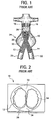
- a prior art prosthetic stent graft for the treatment of AAA.
- the prior art stent graft 10 includes two graft legs, 12, 14, which carry arterial blood from a cephalid region 16 of the abdominal aorta 18, and into the iliac arteries 20, 22, respectively, thereby excluding the aneurysm 24.
- Graft legs 12, 14 are generally circular deployed cross-section, except for where they are held in position in the abdominal aorta 18 by sealing gasket 26.
- the graft legs 12, 14 are held substantially flat against one another within sealing gasket 26.
- Recapture legs 28 depend from sealing gasket 26 and have widened structure 30 at their distal ends to secure the sealing gasket 26 against structure of the delivery apparatus provided for that purpose when crimped for delivery.
- FIG. 2 shown is an axial view of the inlet to stent graft 10.
- Spaces 32, 34 between the sealing gasket 26 and graft legs 12, 14 are filled with a thickened foam to prevent blood flow past the sealing gasket 26 except through graft legs 12, 14.
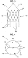
- sealing gasket 100 for a stent graft treating AAA.
- Sealing gasket 100 has a generally cylindrical stent segment 102 which supports, and is preferably surrounded by and secured to a generally cylindrical graft material 104.
- Recapture legs 106 depend from the sealing gasket 100 and have widened structure at their distal ends 108 to secure the sealing gasket 100 against structure of the delivery apparatus provided for that purpose when crimped for delivery.
- recapture legs 106 are shorter, and are preferably no longer than about as long as the diameter of stent segment 102. The shortened recapture legs 106 reduces the range of movement of ends 108, and reduces the likelihood and severity of wear caused by ends 108 on the fabric of the graft legs.
- An upstream or cephalid end of the sealing gasket 100 includes a framing bracket 110 extending in a cephalid direction and generally traversing the diameter of stent segment 102.
- Framing bracket 110 includes two support legs 112 on each side thereof. Support legs 112 connect to the framing bracket 110 at an angle with one another, and connect with the stent segment 102 at different positions around the circumference of the stent segment 102. Together with stent segment 102, framing bracket 110, including support legs 112, defines two windows 114, 116, through which graft legs may pass to be secured by the sealing gasket 100.
- framing bracket 110 includes a centrally located connecting member, for example, a C-shaped tip 118, at its mid-portion.
- the C-shaped tip 118 assists to hold and support a cylindrical inner core of the percutaneous delivery device in its delivery configuration prior to their deployment.
- the open portion of the C-shaped tip 118 permits release of the inner core of the delivery device upon deployment of the sealing gasket 100.
- the lateral extension of the C-shaped tip 118 into windows 114, 166 obstructs any movement of the deployed graft legs in the cephalid or cranial direction.
- the preferred tip merely accommodates a central core of the delivery catheter, is open to one side at the framing bucket 110, and/or extends laterally into windows 114, 116.
- Sealing gasket 100 preferably includes one or more inwardly directed barbs 120 at or near the cephalid portion of the stent segment 102 and on the circumference of windows 114, 116, to engage the graft legs by their fabric or structure to help secure their position once deployed.
- one or more outwardly directed barbs 122 preferably contiguous with and/or an extension of support leg 112. Where barbs 122 are contiguous with support leg 112 or more generally framing bracket 110, they are self-flaring, since they will flare outward with the expansion of the sealing gasket 100. Barbs 122 engage the vessel wall to resist migration of the sealing gasket 100, and resist migration of the graft legs held by sealing gasket 100 as well, once the graft legs are deployed and engaged with sealing gasket 100.
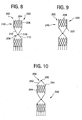
- Figs. 5-7 offer a view of a prototype sealing gasket 100 according to the first embodiment of the present invention, and deployed graft legs 130, 140.
- a compressible foam material omitted from these figures for clarity of illustration, can be placed in the space between sealing gasket 100 and graft legs 130, 140, to prevent blood flow beyond the sealing gasket 100 except through graft legs 130, 140.
- the compressible foam sections are generally aligned with the point of connection between the framing bracket 110 and the stent segment 102.
- a section of vascular graft material can be secured between support legs 112 and the circumference of cylindrical stent segment 102 to inhibit blood flow beyond sealing gasket 100 outside graft legs 130, 140.
- a supra-renal stabilizer portion generally 210, which extends in a cephalid direction of the sealing gasket, generally 200.
- the stabilizer 210 helps to resist migration in the sealing gasket 200, among other benefits.
- stabilizer 210 will be located in the thoracic aorta, i.e., above the junction of the renal arteries.
- Stabilizer 210 includes a generally cylindrical stent segment 204.
- Stent segment 204 is connected to the sealing gasket 202 at a central point 208 defined by the junction of framing bracket 110 and an extension bracket 212.
- Central point 208 may be C-shaped tip 118.
- Extension bracket 212 generally traverses the diameter of stent segment 204.
- sealing gasket 220 includes longitudinally extending barbs 222 at a downstream end of stabilizer 210. Barbs 222 engage the wall of the vessel to resist caudal migration.
- Sealing gasket 250 includes a framing bracket 252 generally traversing the diameter of stent segment 204.
- Framing bracket may include support legs in the same manger as framing bracket 110, and may further include outwardly directed barbs 254, optionally integral with framing bracket 252 or support legs thereof, in the same manner as framing bracket 110.
- Framing bracket 252 may be joined at a central connecting member, e.g. C-shaped tip 256, in the same manner as C-shaped tip 118 of framing bracket 110, providing similar benefits of C-shaped tip 118 as to securing an inner core of the stent delivery apparatus.
- the stabilizer 210 according to the present invention has certain advantages over prior devices.
- the manner of joining stabilizer 210 with sealing gasket 200 minimizes interference with renal blood flow.
- the manner of joining stabilizer 210 with sealing gasket 200 improves transverse flexibility of the sealing gasket 200 as compared with prior devices.
- Stent segments 102, 210, or any associated structure thereof preferably comprises a shape memory material, a group that includes, but is not limited to, Nitinol or a Nitinol alloy. Examples of the latter include Nitinol Niobium (NiTi-Nb), Nitinol Platinum (NiTi-Pt), or Nitinol Tantalum (NiTi-Ta). Stent segments 102, 210, etc., can be formed by cutting the stent from a cylindrical tube of Nitinol or a Nitinol alloy, for example by a laser-cutting technique as is known in the art.
- the present invention has been described herein with reference to certain exemplary or preferred embodiments. These embodiments are offered as merely illustrative, not limiting, of the scope of the present invention.
- the exemplary embodiment is described in the context of treating AAA.
- the invention is not limited to that purpose, and is applicable as a sealing gasket for any prosthetic implant.
- the sealing gasket is also applicable to seal more or fewer than two grafts in other applications.
Landscapes
- Health & Medical Sciences (AREA)
- Gastroenterology & Hepatology (AREA)
- Pulmonology (AREA)
- Cardiology (AREA)
- Oral & Maxillofacial Surgery (AREA)
- Transplantation (AREA)
- Engineering & Computer Science (AREA)
- Biomedical Technology (AREA)
- Heart & Thoracic Surgery (AREA)
- Vascular Medicine (AREA)
- Life Sciences & Earth Sciences (AREA)
- Animal Behavior & Ethology (AREA)
- General Health & Medical Sciences (AREA)
- Public Health (AREA)
- Veterinary Medicine (AREA)
- Prostheses (AREA)
- Media Introduction/Drainage Providing Device (AREA)
- Materials For Medical Uses (AREA)
Claims (24)
- Dichtung (100, 200, 202, 220, 250) für einen prosthetischen vaskulären Stent, welche Folgendes umfasst:ein im Wesentlichen zylindrisches erstes Stentsegment (102) undeinen ersten Rahmenbügel (110), welcher einen Durchmesser des ersten Stentsegments (102) durchquert und sich in eine axiale Richtung von dem ersten Stentsegment (102) weg erstreckt, wobei der erste Rahmenbügel (110) das erste Stentsegment (102) in zwei Teilbereiche (114, 116) jeweils für ein Aufnehmen eines Transplantatbeines unterteilt, dadurch gekennzeichnet, dass der erste Rahmenbügel (110) ein zentral gelegenes Verbindungselement (118) umfasst, wobei das Verbindungselement (118) sich lateral auf jeder Seite des ersten Rahmenbügels (110) erstreckt, und wobei das Verbindungselement (118) eingerichtet ist, um einen zentralen Kern eines Zuführungskatheters aufzunehmen, und zu einer Seite des ersten Rahmenbügels (110) hin offen ist.
- Dichtung (100, 200, 202, 220, 250) nach Anspruch 1, welche weiterhin einen ersten vaskulären Transplantatteilbereich (104) umfasst, welcher durch das erste Stentsegment (102) gestützt wird.
- Dichtung (100, 200, 202, 220, 250) nach Anspruch 2, wobei der erste Transplantatteilbereich (104) das erste Stentsegment (102) umgibt.
- Dichtung (100, 200, 202, 220, 250) nach Anspruch 2, wobei der erste Transplantatteilbereich (104) an dem ersten Stentsegment (102) befestigt ist.
- Dichtung (100, 200, 202, 220, 250) nach Anspruch 1, wobei die Dichtung weiterhin ein Material mit Formgedächtnis umfasst.
- Dichtung (100, 200, 202, 220, 250) nach Anspruch 5, wobei das Material mit Formgedächtnis Nitinol und/oder eine Legierung umfasst, welche Nitinol umfasst.
- Dichtung (100, 200, 202, 220, 250) nach Anspruch 1, wobei der erste Rahmenbügel (110) mit dem ersten Stentsegment (102) an jeder Seite des ersten Rahmenbügels (110) durch eine Mehrzahl von Stützelementen (112) verbunden ist, wobei die Stützelemente (112) einen Winkel miteinander bilden und mit dem ersten Stentsegment (102) an verschiedenen Orten entlang seines Umfangs verbunden sind.
- Dichtung (100, 200, 202, 220, 250) nach Anspruch 7, welche weiterhin eine erste Mehrzahl von nach außen gerichteten Spitzen (122) umfasst, welche auf dem Umfang des ersten Stentsegments (102) positioniert und den Stützelementen (112) des ersten Rahmenbügels (110) benachbart sind.
- Dichtung (100, 200, 202, 220, 250) nach Anspruch 1, welche weiterhin eine Mehrzahl von Rückholbeinen (106) umfasst, welche an dem ersten Stentsegment (102) befestigt sind und sich axial von dem ersten Stentsegment (102) weg in eine Richtung entgegengesetzt zu dem ersten Rahmenbügel (112) erstrecken.
- Dichtung (100, 200, 202, 220, 250) nach Anspruch 9, wobei die Rückholbeine (106) nicht länger sind als ungefähr ein ausgebrachter Durchmesser des im Wesentlichen zylindrischen ersten Stentsegments (102).
- Dichtung (100, 200, 202, 220, 250) nach Anspruch 1, welche weiterhin eine zweite Mehrzahl von nach innen gerichteten Spitzen (120) umfasst, welche auf dem Umfang des ersten Stentsegments (102) positioniert sind.
- Dichtung (100, 200, 202, 220, 250) nach Anspruch 1, welche weiterhin eine dritte Mehrzahl von nach außen gerichteten Spitzen (122) umfasst, welche auf dem Umfang des ersten Stentsegments (102) positioniert sind.
- Dichtung (100, 200, 202, 220, 250) nach Anspruch 12, wobei die dritte Mehrzahl von nach außen gerichteten Spitzen (122) dem ersten Rahmenbügel (110) benachbart ist.
- Dichtung (100, 200, 202, 220, 250) nach Anspruch 1, welche weiterhin zwei im Wesentlichen gegenüberliegende Abschnitte von kompressiblem Dichtungsschaum umfasst, welche an einer inneren Oberfläche des ersten Stentsegments (102) neben jeder Verbindung des ersten Rahmenbügels (110) mit dem ersten Stentsegment (102) befestigt sind.
- Dichtung (100, 200, 202, 220, 250) nach Anspruch 1, welche weiterhin einen Teilbereich von vaskulärem Transplantatmaterial umfasst, welcher den Raum zwischen der Dichtung und einem Transplantatbein zusetzt.
- Dichtung (200, 202, 220, 250) nach Anspruch 1, welche weiterhin einen Stabilisatorteilbereich (210) umfasst, wobei der Stabilisatorteilbereich (210) ein zweites im Wesentlichen zylindrischen Stentsegment (204) und einen Expansionsbügel (212) aufweist, welcher im Wesentlichen den Durchmesser des zweiten Stentsegments (204) durchquert und sich in eine axiale Richtung von dem zweiten Stentsegment (204) weg erstreckt, wobei der Expansionsbügel (212) und der erste Rahmenbügel (110) miteinander an einem im Wesentlichen zentralen Ort des Expansionsbügels (212) und des ersten Rahmenbügels (110) verbunden sind.
- Dichtung (200, 202, 220, 250) nach Anspruch 16, wobei der erste Rahmenbügel (110) und der Expansionsbügel (212) an einem miteinander geteilten zentralen Verbindungselement in der Mitte von sowohl dem ersten Rahmenbügel (110) als auch dem Expansionsbügel (212) verbunden sind.
- Dichtung (220, 250) nach Anspruch 16, welche weiterhin eine Mehrzahl von sich longitudinal erstreckenden Spitzen (222) umfasst, welche von dem zweiten Stentteilbereich (204) in eine Richtung des Expansionsbügels (212) hervorstehen.
- Dichtung (250) nach Anspruch 16, welche weiterhin einen zweiten Rahmenbügel (252) umfasst, welcher einen Durchmesser des zweiten Stentsegments (204) durchquert und sich in eine axiale Richtung von dem zweiten Stentsegment (204) weg und von dem Expansionsbügel (212) weg erstreckt.
- Dichtung (250) nach Anspruch 16, welche weiterhin eine vierte Mehrzahl von sich nach außen erstreckenden Spitzen (254) auf dem Umfang des zweiten Stentsegments (204) umfasst.
- Dichtung (250) nach Anspruch 20, wobei die vierte Mehrzahl von nach außen gerichteten Spitzen (254) dem zweiten Rahmenbügel (252) benachbart ist.
- Dichtung (250) nach Anspruch 16, wobei der zweite Rahmenbügel (252) ein zentral gelegenes Verbindungselement umfasst.
- Dichtung (200, 202, 220, 250) nach Anspruch 16, wobei der erste Rahmenbügel (110) und der Expansionsbügel (212) das erste Stentsegment (102) und das zweite Stentsegment (204) durch zumindest einen Abstand trennen, welcher ausreicht, um zu verhindern, dass das erste Stentsegment (102) oder das zweite Stentsegment (204) einen Blutfluss zu den Renalarterien eines menschlichen Patienten stört, wenn es quer in der Renalarterienverbindung der Aorta ausgebracht ist.
- Dichtung (100, 200, 202, 220, 250) nach Anspruch 1, welche weiterhin eine Mehrzahl von Transplantatbeinen (130, 140) umfasst, wobei jedes in einem jeweiligen Teilbereich des ersten Stentsegments (102) und auf einer Seite des ersten Rahmenbügels (110) positioniert ist.
Applications Claiming Priority (1)
| Application Number | Priority Date | Filing Date | Title |
|---|---|---|---|
| US11/323,781 US8702785B2 (en) | 2005-12-30 | 2005-12-30 | Migration resistant prosthetic stent graft for treatment of abdominal aortic aneurysm |
Publications (3)
| Publication Number | Publication Date |
|---|---|
| EP1825822A2 EP1825822A2 (de) | 2007-08-29 |
| EP1825822A3 EP1825822A3 (de) | 2007-09-26 |
| EP1825822B1 true EP1825822B1 (de) | 2009-12-16 |
Family
ID=38179751
Family Applications (1)
| Application Number | Title | Priority Date | Filing Date |
|---|---|---|---|
| EP06256633A Not-in-force EP1825822B1 (de) | 2005-12-30 | 2006-12-29 | Dichtung für einen prothetischen vaskulären Stent |
Country Status (6)
| Country | Link |
|---|---|
| US (1) | US8702785B2 (de) |
| EP (1) | EP1825822B1 (de) |
| JP (1) | JP5236184B2 (de) |
| AT (1) | ATE451891T1 (de) |
| CA (1) | CA2572621C (de) |
| DE (1) | DE602006011121D1 (de) |
Families Citing this family (7)
| Publication number | Priority date | Publication date | Assignee | Title |
|---|---|---|---|---|
| US11202704B2 (en) * | 2011-10-19 | 2021-12-21 | Twelve, Inc. | Prosthetic heart valve devices, prosthetic mitral valves and associated systems and methods |
| US10828144B2 (en) | 2012-02-27 | 2020-11-10 | Hiroshima University | Stent graft |
| US11123204B2 (en) | 2015-02-06 | 2021-09-21 | Boston Scientific Scimed, Inc. | Anti-migration stent |
| JP6543948B2 (ja) * | 2015-02-10 | 2019-07-17 | 株式会社ジェイ・エム・エス | 生分解性ステント |
| WO2016134148A1 (en) | 2015-02-20 | 2016-08-25 | Boston Scientific Scimed, Inc. | Stent with retractable anchors |
| EP3518836B1 (de) | 2016-11-09 | 2024-02-07 | Boston Scientific Scimed, Inc. | Stentverankerungssystem |
| AU2020242051A1 (en) | 2019-03-20 | 2021-11-04 | inQB8 Medical Technologies, LLC | Aortic dissection implant |
Family Cites Families (12)
| Publication number | Priority date | Publication date | Assignee | Title |
|---|---|---|---|---|
| US6325819B1 (en) | 1996-08-19 | 2001-12-04 | Cook Incorporated | Endovascular prosthetic device, an endovascular graft prothesis with such a device, and a method for repairing an abdominal aortic aneurysm |
| US6290731B1 (en) * | 1998-03-30 | 2001-09-18 | Cordis Corporation | Aortic graft having a precursor gasket for repairing an abdominal aortic aneurysm |
| US6585756B1 (en) | 1999-05-14 | 2003-07-01 | Ernst P. Strecker | Implantable lumen prosthesis |
| US6270525B1 (en) | 1999-09-23 | 2001-08-07 | Cordis Corporation | Precursor stent gasket for receiving bilateral grafts having controlled contralateral guidewire access |
| US6440164B1 (en) * | 1999-10-21 | 2002-08-27 | Scimed Life Systems, Inc. | Implantable prosthetic valve |
| US7226474B2 (en) | 2000-05-01 | 2007-06-05 | Endovascular Technologies, Inc. | Modular graft component junctions |
| US7128754B2 (en) | 2001-11-28 | 2006-10-31 | Aptus Endosystems, Inc. | Catheter-based fastener implantation apparatus and methods |
| US7326237B2 (en) * | 2002-01-08 | 2008-02-05 | Cordis Corporation | Supra-renal anchoring prosthesis |
| US7175656B2 (en) * | 2003-04-18 | 2007-02-13 | Alexander Khairkhahan | Percutaneous transcatheter heart valve replacement |
| US7347869B2 (en) * | 2003-10-31 | 2008-03-25 | Cordis Corporation | Implantable valvular prosthesis |
| EP1621159A1 (de) | 2004-07-28 | 2006-02-01 | Cordis Corporation | Gefäßstütze für Bauchaortenaneurismen mit flachem Profil |
| US8012198B2 (en) * | 2005-06-10 | 2011-09-06 | Boston Scientific Scimed, Inc. | Venous valve, system, and method |
-
2005
- 2005-12-30 US US11/323,781 patent/US8702785B2/en active Active
-
2006
- 2006-12-28 JP JP2006355479A patent/JP5236184B2/ja not_active Expired - Fee Related
- 2006-12-29 AT AT06256633T patent/ATE451891T1/de not_active IP Right Cessation
- 2006-12-29 EP EP06256633A patent/EP1825822B1/de not_active Not-in-force
- 2006-12-29 DE DE602006011121T patent/DE602006011121D1/de active Active
- 2006-12-29 CA CA2572621A patent/CA2572621C/en active Active
Also Published As
| Publication number | Publication date |
|---|---|
| EP1825822A3 (de) | 2007-09-26 |
| ATE451891T1 (de) | 2010-01-15 |
| JP2007185506A (ja) | 2007-07-26 |
| CA2572621A1 (en) | 2007-06-30 |
| EP1825822A2 (de) | 2007-08-29 |
| US8702785B2 (en) | 2014-04-22 |
| US20070156227A1 (en) | 2007-07-05 |
| DE602006011121D1 (de) | 2010-01-28 |
| CA2572621C (en) | 2016-07-05 |
| JP5236184B2 (ja) | 2013-07-17 |
Similar Documents
| Publication | Publication Date | Title |
|---|---|---|
| US6942691B1 (en) | Modular bifurcated graft for endovascular aneurysm repair | |
| US7175651B2 (en) | Stent/graft assembly | |
| US6652580B1 (en) | Modular, staged graft and attachment system for endovascular repair | |
| US7314483B2 (en) | Stent graft with branch leg | |
| EP2574306B1 (de) | Endoluminale Prothese mit steuerbarem Seitenarm | |
| US7232459B2 (en) | Thoracic aortic aneurysm stent graft | |
| US7615072B2 (en) | Endoluminal prosthesis | |
| CA2572720C (en) | Prosthetic stent graft for treatment of abdominal aortic aneurysm | |
| US12201510B2 (en) | Self-curving stent-graft | |
| KR20020075882A (ko) | 혈관 이식편 및 혈관 분지를 브리지 연결하는 방법 | |
| EP1356788A2 (de) | Modulare Anordnong zur Reparatur eines Aneurysmas | |
| CN109996514A (zh) | 模块化主动脉弓假体组件及其使用方法 | |
| US20110218617A1 (en) | Endoluminal vascular prosthesis | |
| WO2014096811A2 (en) | Graft with leg | |
| WO2014096810A1 (en) | Modular fenestrated assembly | |
| EP1825822B1 (de) | Dichtung für einen prothetischen vaskulären Stent | |
| US12409026B2 (en) | Bifurcated stent graft and method of production thereof | |
| GB2517401A (en) | Graft with moveable fenestration |
Legal Events
| Date | Code | Title | Description |
|---|---|---|---|
| PUAI | Public reference made under article 153(3) epc to a published international application that has entered the european phase |
Free format text: ORIGINAL CODE: 0009012 |
|
| PUAL | Search report despatched |
Free format text: ORIGINAL CODE: 0009013 |
|
| AK | Designated contracting states |
Kind code of ref document: A2 Designated state(s): AT BE BG CH CY CZ DE DK EE ES FI FR GB GR HU IE IS IT LI LT LU LV MC NL PL PT RO SE SI SK TR |
|
| AX | Request for extension of the european patent |
Extension state: AL BA HR MK YU |
|
| AK | Designated contracting states |
Kind code of ref document: A3 Designated state(s): AT BE BG CH CY CZ DE DK EE ES FI FR GB GR HU IE IS IT LI LT LU LV MC NL PL PT RO SE SI SK TR |
|
| AX | Request for extension of the european patent |
Extension state: AL BA HR MK YU |
|
| RIC1 | Information provided on ipc code assigned before grant |
Ipc: A61F 2/06 20060101AFI20070823BHEP |
|
| 17P | Request for examination filed |
Effective date: 20080307 |
|
| 17Q | First examination report despatched |
Effective date: 20080418 |
|
| AKX | Designation fees paid |
Designated state(s): AT BE BG CH CY CZ DE DK EE ES FI FR GB GR HU IE IS IT LI LT LU LV MC NL PL PT RO SE SI SK TR |
|
| GRAP | Despatch of communication of intention to grant a patent |
Free format text: ORIGINAL CODE: EPIDOSNIGR1 |
|
| GRAS | Grant fee paid |
Free format text: ORIGINAL CODE: EPIDOSNIGR3 |
|
| GRAA | (expected) grant |
Free format text: ORIGINAL CODE: 0009210 |
|
| AK | Designated contracting states |
Kind code of ref document: B1 Designated state(s): AT BE BG CH CY CZ DE DK EE ES FI FR GB GR HU IE IS IT LI LT LU LV MC NL PL PT RO SE SI SK TR |
|
| REG | Reference to a national code |
Ref country code: GB Ref legal event code: FG4D |
|
| REG | Reference to a national code |
Ref country code: CH Ref legal event code: EP |
|
| REG | Reference to a national code |
Ref country code: IE Ref legal event code: FG4D |
|
| REF | Corresponds to: |
Ref document number: 602006011121 Country of ref document: DE Date of ref document: 20100128 Kind code of ref document: P |
|
| REG | Reference to a national code |
Ref country code: NL Ref legal event code: T3 |
|
| PG25 | Lapsed in a contracting state [announced via postgrant information from national office to epo] |
Ref country code: SE Free format text: LAPSE BECAUSE OF FAILURE TO SUBMIT A TRANSLATION OF THE DESCRIPTION OR TO PAY THE FEE WITHIN THE PRESCRIBED TIME-LIMIT Effective date: 20091216 Ref country code: LT Free format text: LAPSE BECAUSE OF FAILURE TO SUBMIT A TRANSLATION OF THE DESCRIPTION OR TO PAY THE FEE WITHIN THE PRESCRIBED TIME-LIMIT Effective date: 20091216 Ref country code: FI Free format text: LAPSE BECAUSE OF FAILURE TO SUBMIT A TRANSLATION OF THE DESCRIPTION OR TO PAY THE FEE WITHIN THE PRESCRIBED TIME-LIMIT Effective date: 20091216 |
|
| LTIE | Lt: invalidation of european patent or patent extension |
Effective date: 20091216 |
|
| PG25 | Lapsed in a contracting state [announced via postgrant information from national office to epo] |
Ref country code: LV Free format text: LAPSE BECAUSE OF FAILURE TO SUBMIT A TRANSLATION OF THE DESCRIPTION OR TO PAY THE FEE WITHIN THE PRESCRIBED TIME-LIMIT Effective date: 20091216 Ref country code: SI Free format text: LAPSE BECAUSE OF FAILURE TO SUBMIT A TRANSLATION OF THE DESCRIPTION OR TO PAY THE FEE WITHIN THE PRESCRIBED TIME-LIMIT Effective date: 20091216 Ref country code: PL Free format text: LAPSE BECAUSE OF FAILURE TO SUBMIT A TRANSLATION OF THE DESCRIPTION OR TO PAY THE FEE WITHIN THE PRESCRIBED TIME-LIMIT Effective date: 20091216 |
|
| PG25 | Lapsed in a contracting state [announced via postgrant information from national office to epo] |
Ref country code: AT Free format text: LAPSE BECAUSE OF FAILURE TO SUBMIT A TRANSLATION OF THE DESCRIPTION OR TO PAY THE FEE WITHIN THE PRESCRIBED TIME-LIMIT Effective date: 20091216 |
|
| PG25 | Lapsed in a contracting state [announced via postgrant information from national office to epo] |
Ref country code: MC Free format text: LAPSE BECAUSE OF NON-PAYMENT OF DUE FEES Effective date: 20100701 Ref country code: RO Free format text: LAPSE BECAUSE OF FAILURE TO SUBMIT A TRANSLATION OF THE DESCRIPTION OR TO PAY THE FEE WITHIN THE PRESCRIBED TIME-LIMIT Effective date: 20091216 Ref country code: EE Free format text: LAPSE BECAUSE OF FAILURE TO SUBMIT A TRANSLATION OF THE DESCRIPTION OR TO PAY THE FEE WITHIN THE PRESCRIBED TIME-LIMIT Effective date: 20091216 Ref country code: ES Free format text: LAPSE BECAUSE OF FAILURE TO SUBMIT A TRANSLATION OF THE DESCRIPTION OR TO PAY THE FEE WITHIN THE PRESCRIBED TIME-LIMIT Effective date: 20100327 Ref country code: IS Free format text: LAPSE BECAUSE OF FAILURE TO SUBMIT A TRANSLATION OF THE DESCRIPTION OR TO PAY THE FEE WITHIN THE PRESCRIBED TIME-LIMIT Effective date: 20100416 Ref country code: PT Free format text: LAPSE BECAUSE OF FAILURE TO SUBMIT A TRANSLATION OF THE DESCRIPTION OR TO PAY THE FEE WITHIN THE PRESCRIBED TIME-LIMIT Effective date: 20100416 Ref country code: BG Free format text: LAPSE BECAUSE OF FAILURE TO SUBMIT A TRANSLATION OF THE DESCRIPTION OR TO PAY THE FEE WITHIN THE PRESCRIBED TIME-LIMIT Effective date: 20100316 |
|
| PG25 | Lapsed in a contracting state [announced via postgrant information from national office to epo] |
Ref country code: SK Free format text: LAPSE BECAUSE OF FAILURE TO SUBMIT A TRANSLATION OF THE DESCRIPTION OR TO PAY THE FEE WITHIN THE PRESCRIBED TIME-LIMIT Effective date: 20091216 Ref country code: BE Free format text: LAPSE BECAUSE OF FAILURE TO SUBMIT A TRANSLATION OF THE DESCRIPTION OR TO PAY THE FEE WITHIN THE PRESCRIBED TIME-LIMIT Effective date: 20091216 Ref country code: CZ Free format text: LAPSE BECAUSE OF FAILURE TO SUBMIT A TRANSLATION OF THE DESCRIPTION OR TO PAY THE FEE WITHIN THE PRESCRIBED TIME-LIMIT Effective date: 20091216 |
|
| PLBE | No opposition filed within time limit |
Free format text: ORIGINAL CODE: 0009261 |
|
| STAA | Information on the status of an ep patent application or granted ep patent |
Free format text: STATUS: NO OPPOSITION FILED WITHIN TIME LIMIT |
|
| PG25 | Lapsed in a contracting state [announced via postgrant information from national office to epo] |
Ref country code: CY Free format text: LAPSE BECAUSE OF FAILURE TO SUBMIT A TRANSLATION OF THE DESCRIPTION OR TO PAY THE FEE WITHIN THE PRESCRIBED TIME-LIMIT Effective date: 20091216 Ref country code: GR Free format text: LAPSE BECAUSE OF FAILURE TO SUBMIT A TRANSLATION OF THE DESCRIPTION OR TO PAY THE FEE WITHIN THE PRESCRIBED TIME-LIMIT Effective date: 20100317 |
|
| 26N | No opposition filed |
Effective date: 20100917 |
|
| PG25 | Lapsed in a contracting state [announced via postgrant information from national office to epo] |
Ref country code: DK Free format text: LAPSE BECAUSE OF FAILURE TO SUBMIT A TRANSLATION OF THE DESCRIPTION OR TO PAY THE FEE WITHIN THE PRESCRIBED TIME-LIMIT Effective date: 20091216 |
|
| PG25 | Lapsed in a contracting state [announced via postgrant information from national office to epo] |
Ref country code: LU Free format text: LAPSE BECAUSE OF NON-PAYMENT OF DUE FEES Effective date: 20091229 |
|
| PG25 | Lapsed in a contracting state [announced via postgrant information from national office to epo] |
Ref country code: HU Free format text: LAPSE BECAUSE OF FAILURE TO SUBMIT A TRANSLATION OF THE DESCRIPTION OR TO PAY THE FEE WITHIN THE PRESCRIBED TIME-LIMIT Effective date: 20100617 |
|
| REG | Reference to a national code |
Ref country code: CH Ref legal event code: PL |
|
| PG25 | Lapsed in a contracting state [announced via postgrant information from national office to epo] |
Ref country code: TR Free format text: LAPSE BECAUSE OF FAILURE TO SUBMIT A TRANSLATION OF THE DESCRIPTION OR TO PAY THE FEE WITHIN THE PRESCRIBED TIME-LIMIT Effective date: 20091216 |
|
| PG25 | Lapsed in a contracting state [announced via postgrant information from national office to epo] |
Ref country code: CH Free format text: LAPSE BECAUSE OF NON-PAYMENT OF DUE FEES Effective date: 20101231 Ref country code: LI Free format text: LAPSE BECAUSE OF NON-PAYMENT OF DUE FEES Effective date: 20101231 |
|
| REG | Reference to a national code |
Ref country code: FR Ref legal event code: PLFP Year of fee payment: 10 |
|
| REG | Reference to a national code |
Ref country code: FR Ref legal event code: PLFP Year of fee payment: 11 |
|
| PG25 | Lapsed in a contracting state [announced via postgrant information from national office to epo] |
Ref country code: IT Free format text: LAPSE BECAUSE OF NON-PAYMENT OF DUE FEES Effective date: 20151229 |
|
| PG25 | Lapsed in a contracting state [announced via postgrant information from national office to epo] |
Ref country code: IT Free format text: LAPSE BECAUSE OF NON-PAYMENT OF DUE FEES Effective date: 20151229 |
|
| PGRI | Patent reinstated in contracting state [announced from national office to epo] |
Ref country code: IT Effective date: 20170710 |
|
| REG | Reference to a national code |
Ref country code: FR Ref legal event code: PLFP Year of fee payment: 12 |
|
| REG | Reference to a national code |
Ref country code: GB Ref legal event code: 732E Free format text: REGISTERED BETWEEN 20180614 AND 20180620 |
|
| REG | Reference to a national code |
Ref country code: DE Ref legal event code: R082 Ref document number: 602006011121 Country of ref document: DE Representative=s name: PROCK, THOMAS, DR., GB |
|
| REG | Reference to a national code |
Ref country code: NL Ref legal event code: PD Owner name: CARDINAL HEALTH SWITZERLAND 515 GMBH; CH Free format text: DETAILS ASSIGNMENT: CHANGE OF OWNER(S), ASSIGNMENT; FORMER OWNER NAME: CORDIS CORPORATION Effective date: 20200708 |
|
| REG | Reference to a national code |
Ref country code: GB Ref legal event code: 732E Free format text: REGISTERED BETWEEN 20201126 AND 20201202 |
|
| REG | Reference to a national code |
Ref country code: DE Ref legal event code: R082 Ref document number: 602006011121 Country of ref document: DE Representative=s name: PROCK, THOMAS, DR., GB Ref country code: DE Ref legal event code: R081 Ref document number: 602006011121 Country of ref document: DE Owner name: CARDINAL HEALTH SWITZERLAND 515 GMBH, CH Free format text: FORMER OWNER: CORDIS CORP., MIAMI LAKES, FLA., US |
|
| PGFP | Annual fee paid to national office [announced via postgrant information from national office to epo] |
Ref country code: NL Payment date: 20221226 Year of fee payment: 17 Ref country code: IE Payment date: 20221227 Year of fee payment: 17 Ref country code: GB Payment date: 20221227 Year of fee payment: 17 Ref country code: FR Payment date: 20221227 Year of fee payment: 17 |
|
| PGFP | Annual fee paid to national office [announced via postgrant information from national office to epo] |
Ref country code: IT Payment date: 20221221 Year of fee payment: 17 Ref country code: DE Payment date: 20221228 Year of fee payment: 17 |
|
| REG | Reference to a national code |
Ref country code: DE Ref legal event code: R119 Ref document number: 602006011121 Country of ref document: DE |
|
| REG | Reference to a national code |
Ref country code: NL Ref legal event code: MM Effective date: 20240101 |
|
| GBPC | Gb: european patent ceased through non-payment of renewal fee |
Effective date: 20231229 |
|
| PG25 | Lapsed in a contracting state [announced via postgrant information from national office to epo] |
Ref country code: NL Free format text: LAPSE BECAUSE OF NON-PAYMENT OF DUE FEES Effective date: 20240101 |
|
| PG25 | Lapsed in a contracting state [announced via postgrant information from national office to epo] |
Ref country code: NL Free format text: LAPSE BECAUSE OF NON-PAYMENT OF DUE FEES Effective date: 20240101 |
|
| REG | Reference to a national code |
Ref country code: IE Ref legal event code: MM4A |
|
| PG25 | Lapsed in a contracting state [announced via postgrant information from national office to epo] |
Ref country code: DE Free format text: LAPSE BECAUSE OF NON-PAYMENT OF DUE FEES Effective date: 20240702 Ref country code: IE Free format text: LAPSE BECAUSE OF NON-PAYMENT OF DUE FEES Effective date: 20231229 |
|
| PG25 | Lapsed in a contracting state [announced via postgrant information from national office to epo] |
Ref country code: GB Free format text: LAPSE BECAUSE OF NON-PAYMENT OF DUE FEES Effective date: 20231229 |
|
| PG25 | Lapsed in a contracting state [announced via postgrant information from national office to epo] |
Ref country code: FR Free format text: LAPSE BECAUSE OF NON-PAYMENT OF DUE FEES Effective date: 20231231 |
|
| PG25 | Lapsed in a contracting state [announced via postgrant information from national office to epo] |
Ref country code: IE Free format text: LAPSE BECAUSE OF NON-PAYMENT OF DUE FEES Effective date: 20231229 Ref country code: GB Free format text: LAPSE BECAUSE OF NON-PAYMENT OF DUE FEES Effective date: 20231229 Ref country code: FR Free format text: LAPSE BECAUSE OF NON-PAYMENT OF DUE FEES Effective date: 20231231 Ref country code: DE Free format text: LAPSE BECAUSE OF NON-PAYMENT OF DUE FEES Effective date: 20240702 |
|
| PG25 | Lapsed in a contracting state [announced via postgrant information from national office to epo] |
Ref country code: IT Free format text: LAPSE BECAUSE OF NON-PAYMENT OF DUE FEES Effective date: 20231229 |