EP1825982A1 - Dispositif de saisie de données de trou et appareil de traitement de verres de lunettes doté de celui-ci - Google Patents
Dispositif de saisie de données de trou et appareil de traitement de verres de lunettes doté de celui-ci Download PDFInfo
- Publication number
- EP1825982A1 EP1825982A1 EP07004070A EP07004070A EP1825982A1 EP 1825982 A1 EP1825982 A1 EP 1825982A1 EP 07004070 A EP07004070 A EP 07004070A EP 07004070 A EP07004070 A EP 07004070A EP 1825982 A1 EP1825982 A1 EP 1825982A1
- Authority
- EP
- European Patent Office
- Prior art keywords
- hole
- lens
- input device
- data input
- data
- Prior art date
- Legal status (The legal status is an assumption and is not a legal conclusion. Google has not performed a legal analysis and makes no representation as to the accuracy of the status listed.)
- Granted
Links
Images




Classifications
-
- B—PERFORMING OPERATIONS; TRANSPORTING
- B24—GRINDING; POLISHING
- B24B—MACHINES, DEVICES, OR PROCESSES FOR GRINDING OR POLISHING; DRESSING OR CONDITIONING OF ABRADING SURFACES; FEEDING OF GRINDING, POLISHING, OR LAPPING AGENTS
- B24B9/00—Machines or devices designed for grinding edges or bevels on work or for removing burrs; Accessories therefor
- B24B9/02—Machines or devices designed for grinding edges or bevels on work or for removing burrs; Accessories therefor characterised by a special design with respect to properties of materials specific to articles to be ground
- B24B9/06—Machines or devices designed for grinding edges or bevels on work or for removing burrs; Accessories therefor characterised by a special design with respect to properties of materials specific to articles to be ground of non-metallic inorganic material, e.g. stone, ceramics, porcelain
- B24B9/08—Machines or devices designed for grinding edges or bevels on work or for removing burrs; Accessories therefor characterised by a special design with respect to properties of materials specific to articles to be ground of non-metallic inorganic material, e.g. stone, ceramics, porcelain of glass
- B24B9/14—Machines or devices designed for grinding edges or bevels on work or for removing burrs; Accessories therefor characterised by a special design with respect to properties of materials specific to articles to be ground of non-metallic inorganic material, e.g. stone, ceramics, porcelain of glass of optical work, e.g. lenses, prisms
- B24B9/148—Machines or devices designed for grinding edges or bevels on work or for removing burrs; Accessories therefor characterised by a special design with respect to properties of materials specific to articles to be ground of non-metallic inorganic material, e.g. stone, ceramics, porcelain of glass of optical work, e.g. lenses, prisms electrically, e.g. numerically, controlled
-
- B—PERFORMING OPERATIONS; TRANSPORTING
- B24—GRINDING; POLISHING
- B24B—MACHINES, DEVICES, OR PROCESSES FOR GRINDING OR POLISHING; DRESSING OR CONDITIONING OF ABRADING SURFACES; FEEDING OF GRINDING, POLISHING, OR LAPPING AGENTS
- B24B9/00—Machines or devices designed for grinding edges or bevels on work or for removing burrs; Accessories therefor
- B24B9/02—Machines or devices designed for grinding edges or bevels on work or for removing burrs; Accessories therefor characterised by a special design with respect to properties of materials specific to articles to be ground
- B24B9/06—Machines or devices designed for grinding edges or bevels on work or for removing burrs; Accessories therefor characterised by a special design with respect to properties of materials specific to articles to be ground of non-metallic inorganic material, e.g. stone, ceramics, porcelain
- B24B9/08—Machines or devices designed for grinding edges or bevels on work or for removing burrs; Accessories therefor characterised by a special design with respect to properties of materials specific to articles to be ground of non-metallic inorganic material, e.g. stone, ceramics, porcelain of glass
- B24B9/14—Machines or devices designed for grinding edges or bevels on work or for removing burrs; Accessories therefor characterised by a special design with respect to properties of materials specific to articles to be ground of non-metallic inorganic material, e.g. stone, ceramics, porcelain of glass of optical work, e.g. lenses, prisms
-
- B—PERFORMING OPERATIONS; TRANSPORTING
- B24—GRINDING; POLISHING
- B24B—MACHINES, DEVICES, OR PROCESSES FOR GRINDING OR POLISHING; DRESSING OR CONDITIONING OF ABRADING SURFACES; FEEDING OF GRINDING, POLISHING, OR LAPPING AGENTS
- B24B49/00—Measuring or gauging equipment for controlling the feed movement of the grinding tool or work; Arrangements of indicating or measuring equipment, e.g. for indicating the start of the grinding operation
-
- B—PERFORMING OPERATIONS; TRANSPORTING
- B28—WORKING CEMENT, CLAY, OR STONE
- B28D—WORKING STONE OR STONE-LIKE MATERIALS
- B28D1/00—Working stone or stone-like materials, e.g. brick, concrete or glass, not provided for elsewhere; Machines, devices, tools therefor
- B28D1/14—Working stone or stone-like materials, e.g. brick, concrete or glass, not provided for elsewhere; Machines, devices, tools therefor by boring or drilling
- B28D1/143—Working stone or stone-like materials, e.g. brick, concrete or glass, not provided for elsewhere; Machines, devices, tools therefor by boring or drilling lens-drilling machines
-
- G—PHYSICS
- G05—CONTROLLING; REGULATING
- G05B—CONTROL OR REGULATING SYSTEMS IN GENERAL; FUNCTIONAL ELEMENTS OF SUCH SYSTEMS; MONITORING OR TESTING ARRANGEMENTS FOR SUCH SYSTEMS OR ELEMENTS
- G05B19/00—Program-control systems
- G05B19/02—Program-control systems electric
- G05B19/18—Numerical control [NC], i.e. automatically operating machines, in particular machine tools, e.g. in a manufacturing environment, so as to execute positioning, movement or co-ordinated operations by means of program data in numerical form
- G05B19/4093—Numerical control [NC], i.e. automatically operating machines, in particular machine tools, e.g. in a manufacturing environment, so as to execute positioning, movement or co-ordinated operations by means of program data in numerical form characterised by part programming, e.g. entry of geometrical information as taken from a technical drawing, combining this with machining and material information to obtain control information, named part program, for the NC machine
- G05B19/40931—Numerical control [NC], i.e. automatically operating machines, in particular machine tools, e.g. in a manufacturing environment, so as to execute positioning, movement or co-ordinated operations by means of program data in numerical form characterised by part programming, e.g. entry of geometrical information as taken from a technical drawing, combining this with machining and material information to obtain control information, named part program, for the NC machine concerning programming of geometry
- G05B19/40935—Selection of predetermined shapes and defining the dimensions with parameter input
-
- G—PHYSICS
- G05—CONTROLLING; REGULATING
- G05B—CONTROL OR REGULATING SYSTEMS IN GENERAL; FUNCTIONAL ELEMENTS OF SUCH SYSTEMS; MONITORING OR TESTING ARRANGEMENTS FOR SUCH SYSTEMS OR ELEMENTS
- G05B2219/00—Program-control systems
- G05B2219/30—Nc systems
- G05B2219/45—Nc applications
- G05B2219/45175—Glasses, spectacles
-
- Y—GENERAL TAGGING OF NEW TECHNOLOGICAL DEVELOPMENTS; GENERAL TAGGING OF CROSS-SECTIONAL TECHNOLOGIES SPANNING OVER SEVERAL SECTIONS OF THE IPC; TECHNICAL SUBJECTS COVERED BY FORMER USPC CROSS-REFERENCE ART COLLECTIONS [XRACs] AND DIGESTS
- Y02—TECHNOLOGIES OR APPLICATIONS FOR MITIGATION OR ADAPTATION AGAINST CLIMATE CHANGE
- Y02P—CLIMATE CHANGE MITIGATION TECHNOLOGIES IN THE PRODUCTION OR PROCESSING OF GOODS
- Y02P90/00—Enabling technologies with a potential contribution to greenhouse gas [GHG] emissions mitigation
- Y02P90/02—Total factory control, e.g. smart factories, flexible manufacturing systems [FMS] or integrated manufacturing systems [IMS]
Definitions
- the present invention relates to a hole data input device for inputting hole data including a position of a hole with respect to a target lens shape for forming the hole on an eyeglass lens to attach a rimless frame to the lens and an eyeglass lens processing apparatus having the same.
- an eyeglass lens processing apparatus comprising a drilling mechanism for forming a hole on an eyeglass lens to attach a rimless frame such as a two-point frame to the lens by a drilling tool such as an end mill or a drill.
- hole data including a position, a diameter, a depth, and an angle (a direction) of a hole for obtaining drilling data is input.
- one hole may be formed at both of a nose side and an ear side of one lens, or plural holes may be formed at any one or both of the nose side and the ear side of one lens, since plural holes are generally formed on one lens, it is troublesome to input hole data for each hole.
- the invention has a technical object to provide a hole data input device which can carry out an inputting operation of hole data efficiently and an eyeglass lens processing apparatus having the same.
- the invention has a feature to have the following structure in order to solve the problems.
- Fig. 1 is a schematic view showing an appearance of an eyeglass lens processing apparatus according to an embodiment of the invention.
- FIG. 1 is a schematic view showing an appearance of an eyeglass lens processing apparatus according to an embodiment of the invention.
- An eyeglass frame measuring device 2 is connected to an eyeglass lens processing apparatus 1.
- An upper part of the processing apparatus 1 is provided with a touch panel 410 serving as a display portion (display means) for displaying processing information and an input portion (input means and selecting means) for inputting processing conditions, and a switch portion 420 having a switch for giving an instruction for a processing, for example, a processing start switch.
- the touch panel 410 serves as a pointing device in which an input operation is performed on a display screen by a stylus pen 430, an operator's finger, or the like, and includes a hole data input device.
- a lens to be processed is processed in a processing chamber in an opening window 402.
- the processing apparatus 1 may be integrated with the measuring device 2.
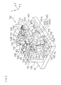
- Fig. 2 is a schematic view showing a structure of a lens processing portion disposed in the processing apparatus 1.
- a carriage portion 700 including a carriage 701 and a moving mechanism thereof is mounted on a base 10.
- a lens LE to be processed is held (chucked) by lens chucks 702L and 702R which are held rotatably on the carriage 701 and is thus rotated, and is subjected to grinding by a grindstone 602.
- the grindstone 602 according to the embodiment includes a roughing grindstone 602a for a glass lens, a roughing grindstone 602b for a plastic lens, and a bevel-finishing and flat-finishing grindstone 602c.
- a grindstone spindle 601a having the grindstone 602 attached thereto is coupled to a grindstone rotating motor 601.
- the lens chucks 702L and 702R are held by the carriage 701 in such a manner that central axes thereof (a rotating central axis of the lens LE) are parallel with a central axis of the grindstone spindle 601a (a rotating central axis of the grindstone 602).
- the carriage 701 can be moved in a direction of the central axis of the grindstone spindle 601a (a direction of the central axes of the lens chucks 702L and 702R) (an X-axis direction), and furthermore, can be moved in an orthogonal direction to the X-axis direction (a direction in which a distance between the central axes of the lens chucks 702L and 702R and the central axis of the grindstone spindle 601a is changed) (a Y-axis direction).
- the lens chuck 702L and the lens chuck 702R are held on a left arm 701L and a right arm 701R of the carriage 701 rotatably and coaxially, respectively.
- a lens holding (chucking) motor 710 is fixed to the right arm 701R, and a rotation of the motor 710 is transmitted to a feed screw (not shown) coupled to a pulley 713 through a pulley 711 attached to a rotating shaft of the motor 710, a belt 712, and the pulley 713, and a feed nut (not shown) into which the feed screw is screwed is moved in an axial direction thereof by a rotation of the feed screw and the lens chuck 702R coupled to the feed nut is moved in an axial direction thereof by the movement of the feed nut. Consequently, the lens chuck 702R is moved in such a direction as to approach the lens chuck 702L, so that the lens LE is held (chucked) by the lens chucks 702L and 702R.
- a lens rotating motor 720 is fixed to the left arm 701L, and a rotation of the motor 720 is transmitted to the lens chuck 702L through a gear 721 attached to a rotating shaft of the motor 720, a gear 722, a gear 723 which is coaxial with the gear 722, a gear 724, and a gear 725 attached to the lens chuck 702L, so that the lens chuck 702L is rotated.
- the rotation of the motor 720 is transmitted to the lens chuck 702R through a rotating shaft 728 coupled to the rotating shaft of the motor 720 and the same gears as the gears 721 to 725, so that the lens chuck 702R is rotated. Consequently, the lens chucks 702L and 702R are rotated synchronously so that the held (chucked) lens LE is rotated.
- a moving support base 740 is movably supported on guide shafts 703 and 704 fixed in parallel with each other over the base 10 and extended in the X-axis direction. Moreover, an X-axis direction moving motor 745 is fixed onto the base 10, and a rotation of the motor 745 is transmitted to the support base 740 through a feed screw (not shown) coupled to a rotating shaft of the motor 745, so that the support base 740 is moved in the X-axis direction. Consequently, the carriage 701 supported on guide shafts 756 and 757 fixed to the support base 740 is moved in the X-axis direction.
- the carriage 701 is movably supported on the guide shafts 756 and 757 fixed to the support base 740 in parallel and extended in the Y-axis direction.
- a Y-axis direction moving motor 750 is fixed to the support base 740 through a plate 751, and a rotation of the motor 750 is transmitted to a feed screw 755 coupled a pulley (not shown) and held rotatably on the plate 751 through a pulley 752 attached to a rotating shaft of the motor 750, a belt 753, and the pulley (not shown), so that the carriage 701 into which the feed screw 755 is screwed is moved in the Y-axis direction by a rotation of the feed screw 755.
- Lens shape measuring portions 500 and 520 are disposed above the carriage 701.
- a drilling and grooving portion 800 is disposed behind the carriage 701.
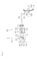
- Fig. 3 is a schematic view showing a structure of the lens measuring portion 500 for measuring a shape (a position of a edge) of a front refractive surface of the lens LE.
- a fixing support base 501 is fixed to a sub base 100 erected from the base 10 (see Fig. 2) and a slider 503 is movably supported on a guide rail 502 fixed to the support base 501 and extended in the X-axis direction.
- a moving support base 510 is fixed to the slider 503 and a feeler arm 504 is fixed to the support base 510.
- An L-shaped feeler hand 505 is fixed to a tip of the arm 504 and a disc-shaped feeler 506 is attached to a tip of the hand 505.
- the feeler 506 is caused to abut on the front refractive surface of the lens LE.
- a rack gear 511 is fixed to a lower part of the support base 510, and a gear 512 attached to a rotating shaft of an encoder 513 fixed to the support base 501 is engaged with the rack gear 511.
- a lens shape measuring motor 516 is fixed to the support base 501 and a rotation of the motor 516 is transmitted to the rack gear 511 through a gear 515 attached to a rotating shaft of the motor 516, a gear 514, and the gear 512, so that the rack gear 511, the support base 510, and the arm 504 are moved in the X-axis direction.
- the motor 516 always causes the feeler 506 to be pushed against the front refractive surface of the lens LE by a certain force.
- the encoder 513 detects an amount of the movement in the X-axis direction of the support base 510 (a position of the feeler 506).
- the shape of the front refractive surface of the lens LE is measured by the amount of the movement (the position) and rotating angles of the lens chucks 702L and 702R.
- the lens measuring portion 520 for measuring a shape (a position of a edge) of a rear refractive surface of the lens LE is laterally symmetrical about the lens measuring portion 500, description of a structure thereof will be omitted.
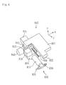
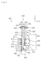
- FIGs. 4 and 5 are schematic views showing a structure of the drilling and grooving portion 800.
- a fixing support base 801 to be a base of the portion 800 is fixed to the sub base 100 (see Fig. 2), and a slider 803 is movably supported on a guide rail 802 fixed to the support base 801 and extended in a Z-axis direction (an orthogonal direction to an XY-axis plane).
- a moving support base 804 is fixed to the slider 803, and a feed screw 806 coupled to a rotating shaft of a Z-axis direction moving motor 805 is screwed into the support base 804.
- the feed screw 806 is rotated by a rotation of the motor 805 fixed to the support base 801, so that the support base 804 is moved in the Z-axis direction.
- a rotating support base 810 is rotatably supported pivotally on the support base 804 through a bearing 811, and a gear 813 is fixed to the support base 810 on either side of the bearing 811.
- a holder rotating motor 816 is fixed to the support base 804, and a rotation of the motor 816 is transmitted to the support base 810 through a gear 815 attached to a rotating shaft of the motor 816, a gear 814, and the gear 813, so that the support base 810 is rotated around an central axis of the bearing 811.
- a processing tool holder 830 for holding a processing tool is provided on a tip of the support base 810.
- the holder 830 is moved in the Z-axis direction by a movement of the support base 804 executed by the motor 805 and is rotated by the rotation of the support base 810 executed by the rotation of the motor 816.
- a rotating shaft 831 is rotatably held pivotally on the holder 830 through two bearings 834 and has one end of the shaft 831 to which an end mill 835 to be a drilling tool is attached through a chuck portion 837 and the other end thereof to which a grooving grindstone 836 to be a grooving tool is attached through a nut 839.
- a cutter may be used in place of the grindstone.
- An end mill and grindstone rotating motor 840 are fixed to the support base 810 through a plate 841, and a rotation of the motor 840 is transmitted to the shaft 831 through a pulley 843 attached to a rotating shaft of the motor 840, a belt 833, and a pulley 832 attached to the shaft 831, so that the shaft 831 is rotated. Consequently, the end mill 835 and the grindstone 836 are rotated.
- shapes of left and right rims of the frame are measured by the measuring device 2, so that data on a target lens shape are obtained.
- a shape of a template (pattern), that of a demo lens (model lens) and the like are measured, so that the target lens shape data thereof are obtained.
- Rn indicates a vector length
- ⁇ n indicates a vector angle.
- a target lens shape graphic based on the target lens shape data is displayed on a screen of the touch panel 410.
- An operator operates a button displayed on the touch panel 410 with the stylus pen 430 or the like to input layout data such as an FPD (a frame papillary distance) of the frame, a PD (a papillary distance) of a user, and a height of an optical center of the lens LE with respect to the geometric center of the target lens shape.
- the operator sets (inputs) the rimless frame (the two-point frame) as a type of the eyeglass frame.
- a hole data input screen on which the hole data can be input is displayed on the touch panel 410.
- the touch panel 410 is controlled by an arithmetic control portion 160.
- the target lens shape data may be input from a database (not shown) or the like.
- Fig. 7 is a view showing an example of the hole data input screen displayed on the touch panel 410.
- Reference numeral FC indicates the geometric center of the target lens shape (the target lens shape graphic) FT.
- Reference numeral 440 indicates a hole pattern icon.
- the icon 440 includes an icon 441 of one circular through-hole pattern, an icon 422 of a pattern in which one notch and one circular through hole are combined (arranged), an icon 443 of a pattern in which two circular through-holes are arranged in a horizontal direction, an icon 444 of a pattern in which two circular through-holes are arranged in a vertical direction, an icon 445 of one horizontally long through-hole pattern, an icon 446 of one vertically long through-hole pattern, and an icon 447 of a pattern in which a counter-bore hole is disposed around one circular through-hole.
- a desired icon is selected from plural types of icons (hole patterns) 440 and is reflected to the target lens shape, so that the hole data with respect to the target lens shape data is input.
- the icon (the hole pattern) 440 includes icons (hole patterns) having a high usage frequency and is stored in a memory 163.
- the position of one hole is designated, so that the position of the other hole arranged next thereto is automatically designated. That is, the positions of two holes arranged in the horizontal direction are simultaneously designated (set) by the arithmetic control portion 160 serving as setting means. Since the nose side and the ear side generally have the same hole pattern in the rimless frame, a third hole is set at a position Ho3 of the ear side within the target lens shape graphic FT and a fourth hole is set at a position Ho4 near thereby by setting the position Ho1 of the nose side.
- the hole position Ho3 of the ear side is set in accordance with the hole position Ho3 of the nose side (for example, so that the hole position Ho1 has the same distance from the edge of the target lens shape rim as the hole position Ho1) and the hole position Ho4 of the ear side is set in accordance with the hole position Ho2 of the nose side (for example, so that the hole position Ho4 has the same distance from the edge of the target lens shape rim as the hole position Ho4).
- the icon 443 is selected, the position of any one of the hole of the nose side and the ear side is designated, so that the position of the other hole is automatically designated.
- the positions of both of the holes of the nose side and the hole of the ear side are simultaneously designated (set) by the arithmetic control portion 160.
- the plural hole positions of any one of the nose side and the ear side is simultaneously designated (set), but the plural hole positions of both of the nose side and the ear side may not be simultaneously designated (set).
- the icon 442 the pattern in which one notch and one circular through-hole are arranged
- the icon 444 the pattern in which two circular through-holes are arranged in the vertical direction
- the hole positions are designated in the same manner as the case when the icon 443 is selected.
- any one of the other hole positions Ho2 to Ho4 may be set as the reference position.
- a middle position between the hole positions Ho1 and Ho2, a middle position between the hole positions Ho3 and Ho4, a middle position between the hole positions Ho1 and Ho3, and a middle position between the hole positions Ho2 and Ho4 also may be set as the reference position.
- the hole positions are designated by an orthogonal coordinate system in which the horizontal direction is generally set as the x axis and the vertical direction is set as a y axis at the time of attaching the frame to the lens based on the target lens shape center FC. Therefore, the orthogonal coordinate system is also used as an example of an orthogonal coordinate system in Fig. 7 (the x axis and the y axis are different from the X axis and the Y axis of the lens processing portion).
- the positions of the stylus pen 430 moving the icon 440 is sequentially displayed an x-axis position column 412a and a y-axis position column 412b. Accordingly, it is possible to designate the hole position with reference to the displayed position.
- the position on the x axis may be selected from a size xc1 (based on a center) from the target lens shape center FC, a size xbl (based on a B-edge) from an edge of the nose side or the ear side of the target lens shape, and a size xh1 (based on a H-edge) from an edge of the nose side or the ear side near the holes by a button 411b.
- the position on the y axis is selected only from a size yc1 (based on the center) from the target lens shape center FC, but may be selected in the same manner as in the method of displaying the position on the x axis (for example, a size from an edge of the upper side or lower side of the target lens shape).
- the hole position is adjusted after the hole position is designated (set) by moving the icon 440, the hole position is adjusted (input) by numeric keypads displayed by pressing the columns 412a and 412b.
- a diameter of the other hole is automatically (simultaneously) set by the arithmetic control portion 160.
- a reference hole diameter based on the selected hole pattern is set.
- a reference hole depth based on the selected hole pattern is set.
- An automatic drilling mode is designated by a hole angle (direction) designating button 417 for a hole depth-directional angle (a hole depth-direction).
- the hole angle (the hole direction) is set so that the hole is formed in a direction (a normal direction) orthogonal to the front refractive surface of the lens LE at each hole position by the arithmetic control portion 160 and when the hole pattern in which plural holes are arranged at any one or both of the nose side and the ear side is selected, the hole angle (the hole direction) is set so that the hole is formed in a direction (a normal direction) orthogonal to the front refractive surface of the lens LE at a middle position between the two arranged hole positions by the arithmetic control portion 160.
- a hole interval input column 418 is displayed. Therefore, when a hole interval is input by the numeric keypads displayed by pressing the column 418, an arranging interval of the plural holes are set (changed) by the arithmetic control portion 160. When the hole interval is not input into the column 418, a reference hole arranging interval based on the selected hole pattern is set. When the hole pattern in which the plural holes are arranged at any one or both of the nose side and the ear side is selected, a hole arrangement column 419 is displayed.
- an arrangement angle (an arrangement direction) of the plural holes is set (changed) by the arithmetic control portion 160 as shown in Fig. 8.
- the position Ho1 of an outer hole of the two holes arranged in the horizontal direction serves as the reference position, but the position Ho2 of an inner hole may serve as the reference position.
- the positions of two holes arranged in the vertical direction may serve as the reference arrangement.
- the positions, diameters, depths, angles (directions), arranging intervals, and arrangement angles (arrangement directions) of the holes may be input before the reference position (the hole position Ho1 described above) is designated (input). Particularly, since the hole arranging intervals influence on an automatic (simultaneous) designation (input) of the hole positions, the hole arranging intervals are preferably input before the reference position is designated (input).
- the input hole data is stored in the memory 161.
- the plural hole positions can be separately input by designating hole numbers with a button 411a.
- an automatic (simultaneous) setting function is changed to an 'off' state on a menu screen displayed by pressing a menu button 415 so as to stop the automatic (simultaneous) setting function of the hole position or the like.
- the hole positions are designated (input) by moving (dragging and dropping) the icons 440, but may be not limited thereto.
- the hole positions may be designated (input) by designating a desired position within the target lens shape graphic FT after selecting any one of the icons 440.
- the pointing device is not limited to the touch panel, but may include a combination of a monitor and a mouse of a PC (Personal Computer), which is widely known.
- the pointing device may include a device in which the display portion and the input portion are separately constructed.
- the lens LE When necessary data such as the hole data can be input, the lens LE is held (chucked) by the lens chucks 702L and 702R and the processing start switch of the switch portion 420 is pressed down to operate the apparatus.
- the arithmetic control portion 160 controls the lens measuring portions 500 and 520 based on the target lens shape data which is input and measures the shape of the lens LE.
- the motor 750 is driven to move the carriage 701 in the Y-axis direction in accordance with the vector data while the motor 720 is driven to rotate the lens LE.
- the feeler 506 is moved in the direction of the central axes of the lens chucks 702L and 702R (the X-axis direction) along the front refractive surface shape of the lens LE.
- zn indicates a height (thickness) of the front refractive surface of the lens LE.
- the rear refractive surface shape of the lens LE is also measured by the lens measuring portion 520. Data on the front and rear refractive surface shapes of the lens LE thus measured are stored in the memory 161. The position of the front edge corresponding to the hole positions (including the middle position between two holes) and the position of the front edge located outer than the hole positions by a predetermined distance are measured, so that an inclination angle ⁇ 1 of the front refractive surface of the lens LE is obtained.
- the arithmetic control portion 160 obtains an inclination angle ⁇ 2 to the rotating central angle of the lens LE (the central axes of the lens chucks 702L and 702R) in the direction (the normal direction) orthogonal to the front refractive surface of the lens LE at the hole position (the middle position between two holes) based on the obtained inclination angle ⁇ 1 as shown in Fig. 9A.
- an arranging interval d of two holes is set so as not to be an interval on a plane orthogonal to the rotating central axis of the lens LE, but so as to be an interval on a plane orthogonal in the normal direction.
- the arithmetic control portion 160 obtains drilling data based on the measuring result and the input hole data.
- the drilling data includes rotation data of the lens LE, moving data of the carriage 701 in the X- and Y-axis directions, moving data of the portion 800 in the Z-direction, and rotation data of the holder 830.
- the arithmetic control portion 160 obtains peripheral edge processing data including roughing data and finishing data on the basis the measuring result.
- the arithmetic control portion 160 moves the carriage 701 in the X-axis direction by driving the motor 745 so as to position the lens LE on the roughing grindstone 602b. Then, the arithmetic control portion 160 rotates the lens LE by driving the motor 720 and moves the carriage 701 in the Y-axis direction by driving the motor 750 to rough the lens LE based on the roughing data. Next, the arithmetic control portion 160 moves the carriage 701 in the X-axis direction so as to position the lens LE on a flat part of the finishing grindstone 602c. Then, the arithmetic control portion 160 rotates the lens LE and moves the carriage 701 in the Y-axis direction to flat-finishing the lens LE based on the finishing data.
- the processing proceeds to the drilling.
- the hole angle ⁇ 2 is obtained in a middle position between the hole positions Ho1 and Ho2 as shown in Fig. 9A. As shown in Fig.
- the arithmetic control portion 160 inclines a rotating central axis of the end mill 835 with respect to the rotating central axis direction of the lens LE by the angle ⁇ 2 by driving the motor 816 to rotate the holder 830, and furthermore, controls the rotation of the lens LE by driving the motor 720 and the movement in the X-and Y-axis directions of the carriage 701 by driving the motors 745 and 750, and places the tip of the end mill 835 in the hole position Ho1. Then, the end mill 835 is rotated by driving the motor 840, thereby moving the carriage 701 in the X- and Y-axis directions in the rotating central axis direction of the end mill 835 (the direction of the angle ⁇ 2). Thus, the drilling is executed. Referring to another hole position Ho2, similarly, the tip of the end mill 835 is placed in the hole position Ho2 with the angle ⁇ 2, thereby carrying out the drilling in the same manner.
- the hole position Ho6 in this embodiment when any one (the hole position Ho6 in this embodiment) of the hole positions Ho5 to Ho8 is selected with the stylus pen 430 and is moved in a direction of an arrow A (only in the Y-axis direction), the hole position Ho5 is automatically moved along the edge of the target lens shape in a direction of an arrow B to form a hole position Ho9 and the hole position Ho6 is automatically moved in a direction of an arrow C parallel to the direction of the arrow B to form a hole position Ho10.
- the hole position Ho7 at an opposite side thereof is automatically moved along the edge of the target lens shape in a direction of an arrow D to form a hole position Ho11 and the hole position Ho8 is automatically moved in a direction of an arrow E parallel to the direction of the arrow D to form a hole position Ho12 (see Fig. 10B).
- the hole positions Ho5 and Ho7 of the notch are certainly on the edge of the target lens shape, the hole positions Ho5 and Ho7 are not moved on the edge of the target lens shape.
- the hole positions Ho6 and Ho8 of the circular hole making a set with the notch also move while maintaining the hole interval d between the hole positions Ho5 and Ho7.
- the control is not limited to the combination pattern of the notch and one circular through-hole.
- the hole position may not be moved inwardly from the edge of the target lens shape by a set distance or more when the hole position is moved in the direction (only in the Y-axis direction) of the arrow A.
- control can be executed when a nonthrough-hole such as a counter-bore hole is formed.
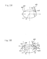
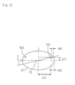
- the hole angle (the hole direction) set to be orthogonal to the front refractive surface of the lens LE is modified (adjusted) in the automatic drilling mode will be described with reference to Figs. 11 to 13 (one circular through-hole pattern).
- the hole positions with respect to the target lens shape (the target lens shape graphic) FT are designated.
- the icon 441 is selected with the stylus pen 430 and is moved to the hole position Ho1 of the nose side within the target lens shape graphic FT, a first hole is set at the hole position Ho1 and a second hole is set at the hole position Ho2 of the ear side (see Fig. 11).
- the automatic drilling mode is designated (selected) with the button 417.
- the hole angle (the hole direction) is not known, the hole angle is not displayed in a hole angle column 417a (see Fig. 11).
- 0.8 mm which is a diameter of the end mil 835 serving as a diameter of a temporary hole is input into the hole diameter column 413 so that a real hole is formed after the temporary hole is formed and an attachment state of the rimless frame is verified (see Fig. 11).
- the arithmetic control portion 160 obtains the inclination angle ⁇ 1 of the front refractive surface of the lens LE at the hole position (the inclination angle at the hole position Ho1 in this embodiment) based on the shape of the front refractive surface of the lens LE.
- the arithmetic control portion 160 obtains the hole angle ⁇ 2 at the hole position Ho1 based on the obtained inclination angle ⁇ 1.
- the inclination angle ⁇ 1 may be manually input by the touch panel 410 and may be input from an external device.
- the lens LE is removed from the lens chucks 702L and 702R, thereby verifying whether the temporary hole is matched with the frame.
- a retouch switch (mode selecting means) of the switch portion 420 is pressed, a reprocessing mode is executed, so that a menu screen for a reprocessing operation is displayed on the touch panel 410.
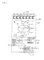
- a hole data input screen for the reprocessing operation is displayed (see Fig. 12).
- the drilling data and the hole data including the inclination angle ⁇ 1 and the hole angle ⁇ 2 before the reprocessing operation are stored in the memory 161 in the reprocessing mode and are displayed on the hole data input screen for the reprocessing operation.
- the hole angle ⁇ 2 set in the automatic drilling mode is displayed in the hole angle column 417a.
- the increased and decreased angles to the hole angle ⁇ 2 are input by the numeric keypads displayed by pressing an modified hole angle column 417b, thereby modifying the hole angle ⁇ 2.
- Fig. 12 The drilling data and the hole data including the inclination angle ⁇ 1 and the hole angle ⁇ 2 before the reprocessing operation are stored in the memory 161 in the reprocessing mode and are displayed on the hole data input screen for the reprocessing operation.
- the hole angle ⁇ 2 set in the automatic drilling mode is displayed in the hole angle column 417a.
- the modification of the hole angle ⁇ 2 is executed in a direction of a p-axis passing the reference point FC and a hole position to be modified (the hole position Ho1 in this embodiment), but the hole angle ⁇ 2 may be modified in the x-axis direction, the y-axis direction, or a direction combining both directions.
- the modified hole angle ⁇ 2 (32° in an example of Fig. 12) may be input into the column 417b.
- the arithmetic control portion 160 controls the mechanisms so that the processing of the modified item is executed.
- the arithmetic control portion 160 obtains the rotation data of the lens LE, the moving data of the carriage 701 in the X- and Y-axis directions, the moving data of the portion 800 in the Z-direction, and the rotation data of the holder 830 based on the modified hole angle to execute the re-drilling on the basis thereof.
- the hole data input device including the touch panel, etc. is provided integrally with the eyeglass lens surrounding apparatus, but the invention is not limited to the case.
- the hole data input device may be provided in an eyeglass frame measuring apparatus.
- the hole data input device may be provided in a peripheral apparatus used in relation with the eyeglass lens processing apparatus, such as a cup attaching apparatus attaching a cup serving as a processing jig to an eyeglass lens to be processed.
- the hole data input device may serve as a dedicated device. In the dedicated device, the hole data input (set) by the hole data input device is transmitted (output) to the eyeglass lens processing apparatus via communication means.
Landscapes
- Engineering & Computer Science (AREA)
- Mechanical Engineering (AREA)
- Physics & Mathematics (AREA)
- Chemical & Material Sciences (AREA)
- Ceramic Engineering (AREA)
- Inorganic Chemistry (AREA)
- Manufacturing & Machinery (AREA)
- Human Computer Interaction (AREA)
- Geometry (AREA)
- General Physics & Mathematics (AREA)
- Automation & Control Theory (AREA)
- Mining & Mineral Resources (AREA)
- Drilling And Boring (AREA)
- Eyeglasses (AREA)
- Perforating, Stamping-Out Or Severing By Means Other Than Cutting (AREA)
- Grinding And Polishing Of Tertiary Curved Surfaces And Surfaces With Complex Shapes (AREA)
Applications Claiming Priority (1)
| Application Number | Priority Date | Filing Date | Title |
|---|---|---|---|
| JP2006054186A JP4749892B2 (ja) | 2006-02-28 | 2006-02-28 | 穴データ入力装置及びこれを備える眼鏡レンズ加工装置 |
Publications (2)
| Publication Number | Publication Date |
|---|---|
| EP1825982A1 true EP1825982A1 (fr) | 2007-08-29 |
| EP1825982B1 EP1825982B1 (fr) | 2009-11-04 |
Family
ID=38068592
Family Applications (1)
| Application Number | Title | Priority Date | Filing Date |
|---|---|---|---|
| EP07004070A Active EP1825982B1 (fr) | 2006-02-28 | 2007-02-27 | Dispositif de saisie de données de trou et appareil de traitement de verres de lunettes doté de celui-ci |
Country Status (7)
| Country | Link |
|---|---|
| US (1) | US7500315B2 (fr) |
| EP (1) | EP1825982B1 (fr) |
| JP (1) | JP4749892B2 (fr) |
| KR (1) | KR101403181B1 (fr) |
| CN (1) | CN101030078B (fr) |
| DE (1) | DE602007003035D1 (fr) |
| ES (1) | ES2333986T3 (fr) |
Cited By (1)
| Publication number | Priority date | Publication date | Assignee | Title |
|---|---|---|---|---|
| EP1884333A1 (fr) * | 2006-07-31 | 2008-02-06 | Nidek Co., Ltd. | Procédé de traitement de verres à lunettes |
Families Citing this family (17)
| Publication number | Priority date | Publication date | Assignee | Title |
|---|---|---|---|---|
| JP4841269B2 (ja) * | 2006-02-28 | 2011-12-21 | 株式会社ニデック | 眼鏡レンズ加工装置 |
| JP4975469B2 (ja) * | 2007-02-02 | 2012-07-11 | 株式会社ニデック | 眼鏡レンズ加工装置 |
| JP5139792B2 (ja) * | 2007-12-19 | 2013-02-06 | 株式会社トプコン | 玉型形状測定装置 |
| JP5143541B2 (ja) * | 2007-12-19 | 2013-02-13 | 株式会社トプコン | 玉型形状測定装置 |
| JP5435918B2 (ja) * | 2008-09-30 | 2014-03-05 | 株式会社トプコン | 玉型形状測定方法及びその装置 |
| JP5356082B2 (ja) * | 2009-03-26 | 2013-12-04 | 株式会社ニデック | 眼鏡レンズ加工装置 |
| JP5420957B2 (ja) | 2009-03-31 | 2014-02-19 | 株式会社ニデック | 眼鏡レンズ加工装置 |
| TWI443554B (zh) * | 2009-08-05 | 2014-07-01 | Silicon Integrated Sys Corp | 觸碰感測裝置及其方法 |
| US9599839B2 (en) * | 2013-03-15 | 2017-03-21 | Jeff Long | Eyeglasses with rotationally secured circular lenses, lens jig and method of jig use |
| US10399171B2 (en) * | 2015-01-29 | 2019-09-03 | Messer Cutting Systems Inc. | Systems and methods for cutting a plow bolt hole with a cutting torch |
| CN106002535B (zh) * | 2015-03-31 | 2020-05-22 | 尼德克株式会社 | 眼镜镜片加工装置 |
| KR102025285B1 (ko) | 2015-11-06 | 2019-09-26 | 주식회사 엘지화학 | 배터리 팩 내부 커패시터 크랙 검출 방법 및 시스템 |
| KR102344250B1 (ko) | 2016-07-01 | 2021-12-27 | 가부시키가이샤 니데크 | 안경 렌즈 가공 장치 및 가공 제어 데이터 작성 프로그램 |
| JP6690438B2 (ja) * | 2016-07-01 | 2020-04-28 | 株式会社ニデック | 眼鏡レンズ加工装置および加工制御データ作成プログラム |
| CN107042443B (zh) * | 2017-05-23 | 2023-07-28 | 浙江宝乐维科技有限公司 | 一种眼镜片修边装置 |
| CN107042444B (zh) * | 2017-05-23 | 2023-04-25 | 浙江宝乐维科技有限公司 | 眼镜片修边装置 |
| JP7331536B2 (ja) * | 2019-07-31 | 2023-08-23 | 株式会社ニデック | 眼鏡レンズの穴データ入力装置、穴データ入力プログラム及び穴データ入力方法 |
Citations (2)
| Publication number | Priority date | Publication date | Assignee | Title |
|---|---|---|---|---|
| EP1310327A2 (fr) * | 2001-11-08 | 2003-05-14 | Nidek Co., Ltd. | Dispositif d'usinage de verre de lunettes |
| FR2863189A1 (fr) * | 2003-12-03 | 2005-06-10 | Jean-Louis Negroni | Procede de percage de verres optiques a l'aide d'une perceuse a commande numerique, et dispositif de mise en oeuvre dudit procede |
Family Cites Families (13)
| Publication number | Priority date | Publication date | Assignee | Title |
|---|---|---|---|---|
| DE3590087T1 (de) * | 1984-03-02 | 1986-06-05 | Hoya Corp., Tokio/Tokyo | Brillengestellform-Datenvorrichtung |
| US4979311A (en) * | 1990-03-14 | 1990-12-25 | Bizer Jerry L | Instrument for determining the setting of a lens edger device to produce a properly sized lens |
| JP3029054B2 (ja) * | 1991-02-28 | 2000-04-04 | 株式会社ニデック | レンズメータ |
| JP3011526B2 (ja) * | 1992-02-04 | 2000-02-21 | 株式会社ニデック | レンズ周縁加工機及びレンズ周縁加工方法 |
| JPH10249618A (ja) * | 1997-03-11 | 1998-09-22 | Nissan Shatai Co Ltd | 穿孔方法及び穿孔装置 |
| DE19749631C2 (de) * | 1997-11-11 | 1999-10-14 | Rodenstock Optik G | Schablone für ein Brillenglas |
| JP3695988B2 (ja) * | 1999-04-30 | 2005-09-14 | 株式会社ニデック | 眼鏡枠形状測定装置 |
| DE19920925C1 (de) * | 1999-05-06 | 2001-02-08 | Wernicke & Co Gmbh | Randlose Brille mit an den Brillengläsern angeschraubten Bügeln und Nasensteg, und Verwendung einer Brillenglasrandbearbeitungsmaschine zum Herstellen von Langlöchern in Brillengläsern |
| JP2001318351A (ja) * | 2000-05-12 | 2001-11-16 | Vision Megane:Kk | 眼鏡の製造方法 |
| JP2004009201A (ja) * | 2002-06-06 | 2004-01-15 | Toshiba Corp | リムレスレンズ用穴開け加工装置およびこれを用いたレンズ研削加工装置 |
| WO2005025791A1 (fr) * | 2003-09-10 | 2005-03-24 | Vision Optic Co., Ltd. | Procede et dispositif de perçage de lentille |
| CN2684991Y (zh) * | 2004-03-30 | 2005-03-16 | 厦门市万成光学工业有限公司 | 无边框眼镜钻夹具 |
| JP4708035B2 (ja) * | 2005-01-06 | 2011-06-22 | 株式会社ニデック | 眼鏡レンズ加工装置 |
-
2006
- 2006-02-28 JP JP2006054186A patent/JP4749892B2/ja not_active Expired - Lifetime
-
2007
- 2007-02-27 ES ES07004070T patent/ES2333986T3/es active Active
- 2007-02-27 EP EP07004070A patent/EP1825982B1/fr active Active
- 2007-02-27 DE DE602007003035T patent/DE602007003035D1/de active Active
- 2007-02-28 US US11/711,695 patent/US7500315B2/en active Active
- 2007-02-28 CN CN2007100850580A patent/CN101030078B/zh not_active Expired - Fee Related
- 2007-02-28 KR KR1020070020663A patent/KR101403181B1/ko not_active Expired - Fee Related
Patent Citations (2)
| Publication number | Priority date | Publication date | Assignee | Title |
|---|---|---|---|---|
| EP1310327A2 (fr) * | 2001-11-08 | 2003-05-14 | Nidek Co., Ltd. | Dispositif d'usinage de verre de lunettes |
| FR2863189A1 (fr) * | 2003-12-03 | 2005-06-10 | Jean-Louis Negroni | Procede de percage de verres optiques a l'aide d'une perceuse a commande numerique, et dispositif de mise en oeuvre dudit procede |
Cited By (2)
| Publication number | Priority date | Publication date | Assignee | Title |
|---|---|---|---|---|
| EP1884333A1 (fr) * | 2006-07-31 | 2008-02-06 | Nidek Co., Ltd. | Procédé de traitement de verres à lunettes |
| US7611243B2 (en) | 2006-07-31 | 2009-11-03 | Nidek Co., Ltd. | Eyeglass lens processing method |
Also Published As
| Publication number | Publication date |
|---|---|
| ES2333986T3 (es) | 2010-03-03 |
| DE602007003035D1 (de) | 2009-12-17 |
| KR20070089657A (ko) | 2007-08-31 |
| CN101030078A (zh) | 2007-09-05 |
| EP1825982B1 (fr) | 2009-11-04 |
| JP4749892B2 (ja) | 2011-08-17 |
| JP2007229861A (ja) | 2007-09-13 |
| US20070201002A1 (en) | 2007-08-30 |
| US7500315B2 (en) | 2009-03-10 |
| CN101030078B (zh) | 2011-09-07 |
| KR101403181B1 (ko) | 2014-06-02 |
Similar Documents
| Publication | Publication Date | Title |
|---|---|---|
| EP1825982B1 (fr) | Dispositif de saisie de données de trou et appareil de traitement de verres de lunettes doté de celui-ci | |
| JP3916445B2 (ja) | 眼鏡レンズ加工装置 | |
| JP4873878B2 (ja) | 眼鏡レンズ周縁加工装置 | |
| JP2003145400A (ja) | 眼鏡レンズ加工装置 | |
| US7476143B2 (en) | Eyeglass lens processing system | |
| JP4708035B2 (ja) | 眼鏡レンズ加工装置 | |
| EP1815941A1 (fr) | Dispositif d'usinage de verres de lunettes | |
| US7617579B2 (en) | Eyeglass lens processing apparatus | |
| US20080186446A1 (en) | Eyeglass lens processing apparatus | |
| JP2005074560A (ja) | 眼鏡レンズ加工装置 | |
| US8260450B2 (en) | Eyeglass lens processing apparatus | |
| US7510459B2 (en) | Eyeglass lens processing apparatus | |
| US7384326B2 (en) | Facetting area setting device and eyeglass lens processing apparatus | |
| JP4781973B2 (ja) | 眼鏡レンズ加工装置 | |
| JP7331536B2 (ja) | 眼鏡レンズの穴データ入力装置、穴データ入力プログラム及び穴データ入力方法 |
Legal Events
| Date | Code | Title | Description |
|---|---|---|---|
| PUAI | Public reference made under article 153(3) epc to a published international application that has entered the european phase |
Free format text: ORIGINAL CODE: 0009012 |
|
| AK | Designated contracting states |
Kind code of ref document: A1 Designated state(s): AT BE BG CH CY CZ DE DK EE ES FI FR GB GR HU IE IS IT LI LT LU LV MC NL PL PT RO SE SI SK TR |
|
| AX | Request for extension of the european patent |
Extension state: AL BA HR MK YU |
|
| 17P | Request for examination filed |
Effective date: 20080227 |
|
| AKX | Designation fees paid |
Designated state(s): DE ES FR GB |
|
| GRAP | Despatch of communication of intention to grant a patent |
Free format text: ORIGINAL CODE: EPIDOSNIGR1 |
|
| GRAS | Grant fee paid |
Free format text: ORIGINAL CODE: EPIDOSNIGR3 |
|
| GRAA | (expected) grant |
Free format text: ORIGINAL CODE: 0009210 |
|
| AK | Designated contracting states |
Kind code of ref document: B1 Designated state(s): DE ES FR GB |
|
| REG | Reference to a national code |
Ref country code: GB Ref legal event code: FG4D |
|
| REF | Corresponds to: |
Ref document number: 602007003035 Country of ref document: DE Date of ref document: 20091217 Kind code of ref document: P |
|
| REG | Reference to a national code |
Ref country code: DE Ref legal event code: R096 Ref document number: 602007003035 Country of ref document: DE Effective date: 20091217 |
|
| REG | Reference to a national code |
Ref country code: ES Ref legal event code: FG2A Ref document number: 2333986 Country of ref document: ES Kind code of ref document: T3 |
|
| PLBE | No opposition filed within time limit |
Free format text: ORIGINAL CODE: 0009261 |
|
| STAA | Information on the status of an ep patent application or granted ep patent |
Free format text: STATUS: NO OPPOSITION FILED WITHIN TIME LIMIT |
|
| 26N | No opposition filed |
Effective date: 20100805 |
|
| REG | Reference to a national code |
Ref country code: DE Ref legal event code: R097 Ref document number: 602007003035 Country of ref document: DE Effective date: 20100805 |
|
| REG | Reference to a national code |
Ref country code: FR Ref legal event code: PLFP Year of fee payment: 10 |
|
| REG | Reference to a national code |
Ref country code: FR Ref legal event code: PLFP Year of fee payment: 11 |
|
| REG | Reference to a national code |
Ref country code: FR Ref legal event code: PLFP Year of fee payment: 12 |
|
| PGFP | Annual fee paid to national office [announced via postgrant information from national office to epo] |
Ref country code: GB Payment date: 20200219 Year of fee payment: 14 Ref country code: ES Payment date: 20200302 Year of fee payment: 14 |
|
| PGFP | Annual fee paid to national office [announced via postgrant information from national office to epo] |
Ref country code: DE Payment date: 20210216 Year of fee payment: 15 |
|
| GBPC | Gb: european patent ceased through non-payment of renewal fee |
Effective date: 20210227 |
|
| PG25 | Lapsed in a contracting state [announced via postgrant information from national office to epo] |
Ref country code: GB Free format text: LAPSE BECAUSE OF NON-PAYMENT OF DUE FEES Effective date: 20210227 |
|
| REG | Reference to a national code |
Ref country code: ES Ref legal event code: FD2A Effective date: 20220513 |
|
| PG25 | Lapsed in a contracting state [announced via postgrant information from national office to epo] |
Ref country code: ES Free format text: LAPSE BECAUSE OF NON-PAYMENT OF DUE FEES Effective date: 20210228 |
|
| REG | Reference to a national code |
Ref country code: DE Ref legal event code: R119 Ref document number: 602007003035 Country of ref document: DE |
|
| PG25 | Lapsed in a contracting state [announced via postgrant information from national office to epo] |
Ref country code: DE Free format text: LAPSE BECAUSE OF NON-PAYMENT OF DUE FEES Effective date: 20220901 |
|
| P01 | Opt-out of the competence of the unified patent court (upc) registered |
Effective date: 20230517 |
|
| PGFP | Annual fee paid to national office [announced via postgrant information from national office to epo] |
Ref country code: FR Payment date: 20251231 Year of fee payment: 20 |