EP1826151B1 - Procédé et dispositif destinés à stocker des produits chimiques dans un récipient - Google Patents
Procédé et dispositif destinés à stocker des produits chimiques dans un récipient Download PDFInfo
- Publication number
- EP1826151B1 EP1826151B1 EP20070003982 EP07003982A EP1826151B1 EP 1826151 B1 EP1826151 B1 EP 1826151B1 EP 20070003982 EP20070003982 EP 20070003982 EP 07003982 A EP07003982 A EP 07003982A EP 1826151 B1 EP1826151 B1 EP 1826151B1
- Authority
- EP
- European Patent Office
- Prior art keywords
- container
- product
- melting
- feed line
- melting member
- Prior art date
- Legal status (The legal status is an assumption and is not a legal conclusion. Google has not performed a legal analysis and makes no representation as to the accuracy of the status listed.)
- Active
Links
- 238000000034 method Methods 0.000 title claims description 24
- 239000000126 substance Substances 0.000 title claims description 12
- 239000000047 product Substances 0.000 claims description 75
- 238000002844 melting Methods 0.000 claims description 69
- 230000008018 melting Effects 0.000 claims description 69
- 238000003860 storage Methods 0.000 claims description 33
- 238000010438 heat treatment Methods 0.000 claims description 29
- 238000009826 distribution Methods 0.000 claims description 24
- 239000012263 liquid product Substances 0.000 claims description 19
- 239000007788 liquid Substances 0.000 claims description 17
- 239000004020 conductor Substances 0.000 claims description 9
- 238000007667 floating Methods 0.000 claims description 9
- 238000004519 manufacturing process Methods 0.000 claims description 2
- 230000000750 progressive effect Effects 0.000 claims description 2
- 210000001080 enamel organ Anatomy 0.000 description 31
- 239000007789 gas Substances 0.000 description 10
- IJGRMHOSHXDMSA-UHFFFAOYSA-N Atomic nitrogen Chemical compound N#N IJGRMHOSHXDMSA-UHFFFAOYSA-N 0.000 description 6
- 239000010426 asphalt Substances 0.000 description 5
- 239000007787 solid Substances 0.000 description 5
- 239000000295 fuel oil Substances 0.000 description 4
- 230000032683 aging Effects 0.000 description 3
- WOZVHXUHUFLZGK-UHFFFAOYSA-N dimethyl terephthalate Chemical compound COC(=O)C1=CC=C(C(=O)OC)C=C1 WOZVHXUHUFLZGK-UHFFFAOYSA-N 0.000 description 3
- 239000000463 material Substances 0.000 description 3
- 229910052757 nitrogen Inorganic materials 0.000 description 3
- 210000000056 organ Anatomy 0.000 description 3
- 238000006243 chemical reaction Methods 0.000 description 2
- 238000002425 crystallisation Methods 0.000 description 2
- 230000008025 crystallization Effects 0.000 description 2
- 238000011010 flushing procedure Methods 0.000 description 2
- 238000000691 measurement method Methods 0.000 description 2
- 239000000203 mixture Substances 0.000 description 2
- 238000004886 process control Methods 0.000 description 2
- 125000006850 spacer group Chemical group 0.000 description 2
- 230000009182 swimming Effects 0.000 description 2
- 238000009795 derivation Methods 0.000 description 1
- 230000018109 developmental process Effects 0.000 description 1
- 238000005265 energy consumption Methods 0.000 description 1
- 230000002349 favourable effect Effects 0.000 description 1
- 229920002457 flexible plastic Polymers 0.000 description 1
- -1 for example Substances 0.000 description 1
- 230000004927 fusion Effects 0.000 description 1
- 239000012535 impurity Substances 0.000 description 1
- 230000006698 induction Effects 0.000 description 1
- 238000005259 measurement Methods 0.000 description 1
- 239000000155 melt Substances 0.000 description 1
- 239000002184 metal Substances 0.000 description 1
- 238000002156 mixing Methods 0.000 description 1
- 229910052756 noble gas Inorganic materials 0.000 description 1
- 150000002835 noble gases Chemical class 0.000 description 1
- 229920003023 plastic Polymers 0.000 description 1
- 238000005086 pumping Methods 0.000 description 1
- 230000000630 rising effect Effects 0.000 description 1
- 239000000523 sample Substances 0.000 description 1
- 238000007711 solidification Methods 0.000 description 1
- 230000008023 solidification Effects 0.000 description 1
- 239000012209 synthetic fiber Substances 0.000 description 1
- 229920002994 synthetic fiber Polymers 0.000 description 1
- 238000009827 uniform distribution Methods 0.000 description 1
- XLYOFNOQVPJJNP-UHFFFAOYSA-N water Substances O XLYOFNOQVPJJNP-UHFFFAOYSA-N 0.000 description 1
Images



Classifications
-
- B—PERFORMING OPERATIONS; TRANSPORTING
- B65—CONVEYING; PACKING; STORING; HANDLING THIN OR FILAMENTARY MATERIAL
- B65D—CONTAINERS FOR STORAGE OR TRANSPORT OF ARTICLES OR MATERIALS, e.g. BAGS, BARRELS, BOTTLES, BOXES, CANS, CARTONS, CRATES, DRUMS, JARS, TANKS, HOPPERS, FORWARDING CONTAINERS; ACCESSORIES, CLOSURES, OR FITTINGS THEREFOR; PACKAGING ELEMENTS; PACKAGES
- B65D88/00—Large containers
- B65D88/74—Large containers having means for heating, cooling, aerating or other conditioning of contents
- B65D88/744—Large containers having means for heating, cooling, aerating or other conditioning of contents heating or cooling through the walls or internal parts of the container, e.g. circulation of fluid inside the walls
Definitions
- the invention relates to a method and a device for storing chemical products in a container chemical substances that are to be transported in liquid form and further processed, but have a melting point above the desired or usual storage temperature.
- a storage container with a device for suction of a viscous liquid in which a heatable fishing cap is arranged in the container to heat a part of the viscous liquid targeted and make it thinner for the removal can.
- the method with the device described is suitable only for viscous liquids, but not for completely solidifying substances, since the solidified solid could not flow under the hood.
- From the DE 2432955 discloses a process for underground storage of heavy products which solidify at ordinary temperatures, such as heavy oil, in which the surface of the solidified product is contacted with at least one circulating warm liquid and the liquefied product is pumped out becomes.
- the method is designed for underground tunnels and requires a relatively large amount of pumping work to flush out the stored product by the continuous flowing warm liquid. This work is all the greater when a crystallizing product with high heat of fusion is embedded. For heavy oil, a flushing with water is provided, which is not suitable for all products.
- bitumen tank in which a vertical tube is arranged in the container, in the open upper end of the inlet line opens and the lower end is arranged at a distance above the container bottom. If fresh, hot bitumen is filled into the vertical pipe from above, the fresh, hot bitumen is stored in the container from bottom to top according to the principle of communicating pipes. Accordingly, at the end of filling, fresh, hot bitumen is present in the lower area of the container, as a result of which the bitumen tank is ready for use without any external heating for a certain period of time after filling.
- a device for the storage of fusible chemical compositions known The filling takes place in molten, the storage then in the solid state. For removal, a heatable piston is pressed against the composition. The piston thereby represents a melting device for melting the stored product, which is connected to a central outlet for the execution of the product.
- dimethyl terephthalate (DMT, C10H10O4) with a melting range at 140.6 ° C for the synthetic fiber industry liquid provided and therefore previously stored in liquid form. This has so far been done with high energy consumption in heated tanks.
- the object of the invention is therefore to provide a method and an apparatus for storing chemical products in a container, which makes it possible to liquidify and outsource rapidly solidifying products while a part of the product stored in the tank in the solid State is.
- a method for storing chemical products in a tank in which the product is stored in the liquid state at a temperature above its melting temperature in the tank and there at lower ambient temperature in a remplis-tens partially solidified state remains until removal.
- the inventive method is characterized in that the removal of the product from the container at the end of storage is done in such a way that coming out of production or circulated, liquid product via a substantially vertical supply of heat-conducting material into the container introduced and distributed below at least one melting element of heat-conducting material substantially horizontally over the cross-section of the container, wherein the heat content of the liquid product is used in conjunction with the thermal conductivities of the feed line and the melting member or the melting means for melting product located in the container, and withdrawing the product via at least one horizontal flow level below the enamel organ or enamel organs and vertically along the delivery.
- the container may be a tank, ie a storage container generally provided with inlet and outlet, also large-volume with more than 1 m 3 , preferably more than 5 m 3 storage volume.
- the feed line and optionally additionally the surface below the melting member is blown free after the passage of liquid product and filled with a gas until the next use.
- gases introduced should be product-friendly (inert) and as easy as possible to compress.
- air, nitrogen, CO 2 or noble gases may be suitable.
- liquid product may be generated outside a core of solidified product stored below the melting point via an interior wall heating provided on at least one outer wall of the container.
- the liquefied on the outer wall product can then be used for the melting of further, ab diagnosed product or is used during storage for pressure equalization during storage for safe pressure equalization, ie to protect the container walls and internals.
- an approximately ring-shaped core of solidified product enclosed by liquid product can be produced by means of the interior wall heating which facilitates the turbulent mixing of all-round product.
- the removal of product melted down at the interior wall heating can take place in vertical channels, which can be formed, for example, by means of the heat exchanger arranged on the inner wall for the inner wall lining.
- the process may be conducted so that the stored liquid product is allowed to solidify entirely in the container.
- the supply is kept free during the solidification or crystallization process by gas, which is passed to the liquid product by the feed.
- the underside of the (upper) enamel organ can be kept free by gas or blown free.
- the method may be carried out such that a portion of the product stored in the container is kept liquid during heating by heating via heating elements, in particular the interior wall heating and / or the supply and / or the melting member (as the supply and the Melting organ according to the invention from heat-conducting material, they can be easily heated).
- heating elements in particular the interior wall heating and / or the supply and / or the melting member (as the supply and the Melting organ according to the invention from heat-conducting material, they can be easily heated).
- a portion of the product for melting solidified product may preferably be recirculated via an additional, heated, additional container connected to the container.
- the product may also be circulated within the container in one embodiment of the invention.
- a floor heating may be provided.
- the melting occurs in particular by progressive liquefaction from top to bottom and / or from bottom to top, preferably with appropriate movement of the enamel organs.
- the process can be provided as well as the inlet inlet of the feed with a valve.
- the melting member is preferably arranged displaceably along the feed, which allows the gradual melting from top to bottom or bottom to top.
- the feed is designed as a telescopic tube.
- the container is preferably at least partially cylindrical in all embodiments and the feed is along the cylinder axis.
- the container or tank may also have a square or rectangular cross-section; the feeder is preferably centrally located in all embodiments.
- the enamel organ may then preferably comprise an upper enamel organ which has a hat-like shape and is arranged at the end of the feed: in an advantageous embodiment, the upper enamel organ is provided with buoyant bodies, preferably in the form of a floating ring. The swim ring may hold the upper enamel organ at a certain level below or at the product level.
- the melting organ can be set higher or lower by immersing the swim ring filled exclusively with gas or partly with gas and partly with liquid or a suitable medium becomes.
- the swimming ring can also be used for the supply of heat, for example by a heating element is provided in a chamber of the floating ring.
- the enamel organ additionally comprises a lower enamel organ, which preferably extends annularly around the feed in the lower third of the container.
- the enamel organ or the enamel organs may have downwardly facing internals in the form of flow resistances. These flow resistances serve to distribute the liquid product evenly below the respective enamel organ. This is also done by partial damming and swirling.
- an interior wall heating may be provided on at least one outer wall, preferably on a cylindrical outer wall.
- channels can be incorporated for the removal of product (i.a. down).
- the channel melting prevents damage to the container by thermal expansion, as always ensures escape of the resulting forces and thus the container is not mechanically stressed.
- the method can be performed such that first channels are melted vertically into the solidified product and then a cross-sectional surface is melted free below a melting element. The melt from the horizontal melt can then flow off over the previously formed vertical channels.
- the interior wall heating preferably ranges higher than the maximum level of product in the container to keep the entire interior wall surface free from solidified product.
- At the upper melting member guide elements may be provided which engage in a suitable manner to the réellewandwandbeauchung and ensure a continuous and geometrically clear melting zone.
- measuring sensors may be provided, preferably on the melting element or on the melting elements and / or on the outer wall.
- Spatially assigned to the output of the feed can be an asymmetric insert which is variable in its position, for example in the form of a guide plate, with which the product can be given a certain preferred direction during its distribution during storage or removal. This can compensate for free-standing container temperature differences across the container cross-section. In colder areas, more hot liquid product is introduced by means of the distribution insert, so that the solidified stored product can be melted evenly.
- the container can be composed of several parts.
- melting organs, supply and discharge can be arranged on a bottomless container attachment, which is placed, for example, on a capless drum, so that a total of a two-part container according to the invention is formed.
- the drain is either present in the lower region (eg the lower fifth) of the drum or is preferably additionally provided on the tank top, from where the stored molten product can be sucked off.
- the container 1 is a suitable container for the product, in particular cylindrical or cuboidal design and has the following main components.
- the interior wall heating 2a on the outer wall 2 of the container must be aligned with the forces to be expected, the required heat output and mechanical and hydraulic action.
- the upper melting member 3 may be a platform with an upwardly-oriented cylinder (hat 3a) and with arranged on the bottom baffles 10 (internals, flow resistance) and a terminal edge 6 (guide rails).
- the floats 4 may be formed as a floating ring and form a component on the upper melting element 3. Other buoyancy bodies or a split design are possible.
- the floating ring 4 between hat 3a and edge 6 of the upper enamel organ is suspended from adjustable links (ropes).
- the feeder 5 can be a telescopic tube extending automatically by the buoyancy of the floating rings 4 on the upper melting element 3 or, alternatively, a motor-driven extension.
- the telescopic tube or the feeder 5 is optionally with the Distribution insert 9 connected to be able to guide the product particularly. Otherwise, the product is preferably introduced centrally via the telescopic tube.
- the guide rails 6 are fastened to the upper melting member 3 and ensure the distance between the upper melting member 3 and the inner wall heating 2a.
- the inner wall heating 2a may protrude beyond the guide rails 6 by a certain number of heating elements.
- the filling and emptying tube 7 may be a quarter tube welded on the bottom around the feeder 5 and having openings for uniform heat distribution in the direction of the container bottom.
- the filling and emptying tube 7 can be heated via a separate heating coil or via the heat of the feed 5.
- the lower melting member 8 may be provided with drain valves which release the flow when, below them, the product is discharged or the pressure above them is greater.
- the distribution insert 9 is moved by a drive to the respective position determined by the personnel or the process control system.
- the internals 10 in the form of baffles 10 on the underside of the melting members 3.8 serve as flow resistances for distributing and swirling liquid product.
- Sensor 11 and contactor are used to monitor the level and storage condition of the product.
- Float 12 serve to determine how the distance between the melting element is 3.8 and product, ie whether still gas must be supplied or not.
- FIG. 1 shows a designated as a whole with 1 (storage) container, here a cylindrical, standing on a cylinder bottom surface basin-shaped container with oblique roofing.
- 1 (storage) container here a cylindrical, standing on a cylinder bottom surface basin-shaped container with oblique roofing.
- the inner wall heating 2a is attached, which practically covers the entire cylinder surface area here.
- a telescopic tube protrudes as a supply 5 for liquid still hot product into the container - shown here in the fully extended state.
- a plate-shaped upper melting member 3 is arranged, which is slipped over the feed 5 with a hat-shaped middle part (hat) 3a.
- spacers may be provided for the melting member 3, for example in the form of a screen plate (not shown here).
- the melting member 3 is with buoyancy bodies 4, here in the form provided a swimming ring.
- the floating ring 4 is over radially extending ropes, which extend from the hat 3a to the edge of the enamel organ 3, as in FIG. 1a is shown.
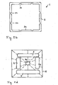
- FIG. 1 a shows the melting member with the buoyant body 4 in plan view from above.
- Figure 1d shows a similar variant for a container with a square cross-section.
- the floating ring 4 is divided into several sections or individual floats.
- guide rails 6 are provided, which provide a guide relative to the inner wall heating 2a.
- a plurality of baffles 10 (from the melting member 3 downwardly facing internals 10) are provided, which ensure a more uniform distribution of the product.
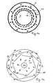
- the internals 10 may be designed in particular, as in Figures 1b and especially 1 c for specific embodiments.
- Figures 1b and 1c show variants of the enamel organs 3 from below. These embodiments are also possible for the lower enamel organs 8 described below.
- FIG. 2 shows a similar container 1, as in FIG. 1 shown, except that in the lower part of the container near the bottom in addition a plate-shaped lower melting member 8 is arranged around the feed 5 around. At the lower melting member 8 drain valves may be provided, as explained above.
- FIG. 2 also shows how the buoyancy bodies hold the fusible link 3 relative to the surface of the product in the container 1.
- the surface is labeled A.
- the buoyancy bodies 4 floating ring
- FIG. 2b shows a corresponding wall heating as in FIG. 2a in a container with a square cross-section.
- the product can be removed via drains close to the edge, or centrally near the feeder, when a lower enamel organ keeps the bottom area in a molten state.
- FIG. 3 shows the container as in FIG. 2 shown in almost or completely deflated condition and with retracted telescopic tube. 5
- FIG. 4 shows the container as in FIG. 1 illustrated with a central filling and emptying tube.
- a quarter tube welded onto the floor around the telescopic tube 5 is provided with openings for uniform heat and product distribution.
- FIGS. 5 and 6 show a container 1 as in FIG. 2 or 3 with an additional distribution insert 9.
- the distribution insert is moved with a drive to the position specified by the personnel or the process control system. Is z. B. when flushing the product on one side of the container colder, the distribution insert is shut down and brought into position, so that the warmer side is shielded. The rising hot product now pushes into the colder regions of the container.
- the distribution insert is installed in the here cylindrical hat 3a of the melting member 3 and connected to the bottom of a telescopic tube 5 via a cylinder. The cylinder ensures a uniform supply of the product and protects the overlying parts.
- the distribution insert may be passed over vertical guide rails and a powered spindle 9a between the molder cap 3a and distribution insert 9. At least two spacers and end stops give the lead at all times. In the upper hat-shaped part of the upper melting member 3 remains a part of the distribution insert 9 to avoid tilting. If the distribution insert 9 is required, it is shut down with the spindle 9a until the vertical guide rails no longer engage. The vertically displaceable spindle 9a has no more thread at the lower end, only one stop, which continues to rotate the distribution insert 9. The distribution insert 9 is now on the end stop and is brought by the drive in the same direction in the desired position. If the distribution insert 9 is no longer needed, the direction of rotation of the drive is changed. Now the spindle 9a sags and the thread engages to pull up the distribution insert 9 again. The guide rails move together again until the drive shuts off
- FIG. 7 shows the detail between outer wall 2 and enamel organ 3 (also possible with enamel organ 8).
- a laser measurement method can determine whether the upper enamel organ 3 is in the horizontal (B).
- the horizontal position of both enamel organs 3 and 8 can also be controlled with a tilt measurement become.
- With the float 12 is to determine whether enough nitrogen is stored. If the piston of the float has retracted, it may be necessary to inject nitrogen. It can also be determined via the float whether the filling level across the cross-section of the container is the same, that is, whether the distribution insert 9 is used. Finally, it can be measured by whether less product must be removed from the container, so that the enamel organ sinks more slowly. Furthermore, if necessary, sensors 11 are provided on the internals 10.
- FIG. 8 is another embodiment of the invention, in which the melting member 3 with feed tube 5a and discharge tube 5b is attached to a container attachment 1a.
- the container attachment 1 a is placed on an open barrel 1 b, so that a multi-part container 1 is formed.
- the level of the stored product is marked with "A".
- the function of the enamel organ is as already described above.
- the suction of the liquefied product takes place here through the discharge pipe 5b by suction from above.
- the product removal takes place first around the valve ball to be designed according to weight and circumference, and with almost complete emptying via the additional suction pipe 5b 'for the remainder removal.
- the container may generally consist of all suitable materials, in particular metal or plastic. It can be collapsible, for example, by using flexible plastic in the deflated state.
Landscapes
- Engineering & Computer Science (AREA)
- Mechanical Engineering (AREA)
- Filling Or Discharging Of Gas Storage Vessels (AREA)
- Feeding, Discharge, Calcimining, Fusing, And Gas-Generation Devices (AREA)
- Agricultural Chemicals And Associated Chemicals (AREA)
Claims (15)
- Procédé destiné à stocker des produits chimiques dans un récipient (1), dans lequel on stocke le produit à l'état liquide dans le récipient à une température supérieure à sa température de fusion et il y reste à une température ambiante plus basse dans un état au moins partiellement solidifié jusqu'à son enlèvement, dans lequel l'évacuation du produit hors du récipient à la fin du stockage est effectuée de telle manière que le produit liquide, venant de la production ou mis en circulation, soit introduit dans le récipient (1) par un moyen d'alimentation essentiellement vertical (5) en matériau conducteur de la chaleur et soit réparti de manière essentiellement horizontale sur la section transversale du récipient (1) en dessous d'au moins un organe de fusion (3; 8) en matériau conducteur de la chaleur, dans lequel la capacité calorifique du produit liquide est utilisée en liaison avec les conductibilités calorifiques du moyen d'alimentation (5) et de l'organe de fusion/des organes de fusion (3; 8) pour fondre du produit se trouvant dans le récipient (1), et le produit est extrait par au moins un plan d'écoulement horizontal en dessous de l'organe de fusion/des organes de fusion (3; 8) et verticalement le long du moyen d'alimentation (5).
- Procédé selon la revendication 1, caractérisé en ce que le moyen d'alimentation (5) est dégagé par soufflage après le passage de produit liquide et reste rempli d'un gaz jusqu'à la prochaine utilisation.
- Procédé selon la revendication 1 ou 2, caractérisé en ce que la surface en dessous de l'organe de fusion (3; 8) est en plus dégagée par soufflage après le passage de produit liquide et reste remplie d'un gaz jusqu'à la prochaine utilisation.
- Procédé selon l'une quelconque des revendications 1 à 3, caractérisé en ce que l'on produit en plus du produit liquide à l'extérieur d'un noyau de produit solidifié stocké en dessous du point de fusion au moyen d'un chauffage de paroi d'espace intérieur (2a) prévu à au moins une paroi extérieure (2) du récipient (1) et on l'utilise de préférence pour la fusion de produit supplémentaire à évacuer pour l'équilibre de pression lors du stockage.
- Procédé selon l'une quelconque des revendications 1 à 4, caractérisé en ce que l'on maintient à l'état liquide, pendant le stockage, une partie du produit stocké dans le récipient par chauffage au moyen d'éléments chauffants, en particulier le chauffage de paroi d'espace intérieur (2a) et/ou le moyen d'alimentation (5) et/ou l'organe de fusion (3; 8).
- Procédé selon l'une quelconque des revendications 1 à 5, caractérisé en ce que l'on met en circulation ou on met en circulation à l'intérieur du récipient (1) une partie du produit pour la fusion de produit solidifié au moyen d'un récipient d'appoint supplémentaire chauffé, relié au récipient (1).
- Procédé selon l'une quelconque des revendications 1 à 6, caractérisé en ce que la fusion est effectuée par liquéfaction progressive de haut en bas et/ou de bas en haut par un déplacement correspondant des organes de fusion (3; 8).
- Dispositif destiné à stocker des produits chimiques, qui présentent un point de fusion situé en dessous de la plage de température de stockage, dans un récipient (1) et en particulier pour la mise en oeuvre d'un procédé selon l'une quelconque des revendications 1 à 7, dans lequel le dispositif comprend les éléments suivants:- un récipient (1) en une ou plusieurs parties;- un moyen d'alimentation (5) s'étendant essentiellement verticalement à l'intérieur du récipient (1), pour le produit liquide et du gaz, en matériau conducteur de la chaleur;- au moins un organe de fusion (3; 8) s'étendant essentiellement horizontalement sur la section transversale du récipient, en matériau conducteur de la chaleur, qui est disposé autour du moyen d'alimentation (5) et qui permet de guider et de répartir le produit liquide apporté;- au moins un moyen d'évacuation.
- Dispositif selon la revendication 8, caractérisé en ce que l'organe de fusion (3; 8) est disposé de façon mobile le long du moyen d'alimentation (5), en particulier du fait que le moyen d'alimentation (5) est réalisé sous la forme d'un tube télescopique.
- Dispositif selon l'une quelconque des revendications 8 à 9, caractérisé en ce qu'un organe de fusion supérieur (3) a la forme d'un chapeau et est disposé à l'extrémité du moyen d'alimentation (5).
- Dispositif selon l'une quelconque des revendications 8 à 10, caractérisé en ce que l'organe de fusion (3; 8) comprend un organe de fusion inférieur (8).
- Dispositif selon l'une quelconque des revendications 8 à 11, caractérisé en ce que l'organe de fusion supérieur (3) est équipé de corps de montée (4), en particulier sous la forme d'un anneau flottant (4).
- Dispositif selon l'une quelconque des revendications 8 à 12, caractérisé en ce que l'organe de fusion/les organes de fusion (3; 8) présente/présentent des pièces dirigées vers le bas (10) sous la forme de résistances à l'écoulement.
- Dispositif selon l'une quelconque des revendications 8 à 13, caractérisé en ce que le récipient (1) comporte, sur au moins une paroi extérieure (2), en particulier sur une paroi extérieure cylindrique, un chauffage de paroi d'espace intérieur (2a).
- Dispositif selon l'une quelconque des revendications 8 à 14, caractérisé en ce qu'il est prévu, en association avec la sortie du moyen d'alimentation (5), un moyen de répartition asymétrique (9), dont la position est variable, en particulier sous la forme d'un déflecteur, avec lequel une certaine direction préférée peut être conférée au produit lors de sa répartition pendant le stockage ou l'enlèvement.
Applications Claiming Priority (1)
| Application Number | Priority Date | Filing Date | Title |
|---|---|---|---|
| DE200610009501 DE102006009501B4 (de) | 2006-02-27 | 2006-02-27 | Verfahren und Vorrichtung zum Lagern chemischer Produkte in einem Tank |
Publications (3)
| Publication Number | Publication Date |
|---|---|
| EP1826151A2 EP1826151A2 (fr) | 2007-08-29 |
| EP1826151A3 EP1826151A3 (fr) | 2008-05-21 |
| EP1826151B1 true EP1826151B1 (fr) | 2012-12-05 |
Family
ID=38222722
Family Applications (1)
| Application Number | Title | Priority Date | Filing Date |
|---|---|---|---|
| EP20070003982 Active EP1826151B1 (fr) | 2006-02-27 | 2007-02-27 | Procédé et dispositif destinés à stocker des produits chimiques dans un récipient |
Country Status (3)
| Country | Link |
|---|---|
| EP (1) | EP1826151B1 (fr) |
| DE (1) | DE102006009501B4 (fr) |
| ES (1) | ES2399837T3 (fr) |
Families Citing this family (2)
| Publication number | Priority date | Publication date | Assignee | Title |
|---|---|---|---|---|
| AU2014226651A1 (en) * | 2013-03-08 | 2015-09-17 | Technix Industries Limited | Bitumen transport and/or storage container |
| CN110775463A (zh) * | 2018-07-30 | 2020-02-11 | 熊贱林 | 一种散热效果好的化工存储罐 |
Family Cites Families (5)
| Publication number | Priority date | Publication date | Assignee | Title |
|---|---|---|---|---|
| DE8331135U1 (de) * | 1984-02-09 | Deutag-Mischwerke GmbH, 5000 Köln | Bitumentank | |
| DE534084C (de) * | 1930-10-25 | 1932-01-08 | Carl Tiburtius | Einrichtung zum Absaugen einer zaehen Fluessigkeit aus einem Vorratsbehaelter |
| FR2236751B1 (fr) * | 1973-07-10 | 1977-08-05 | Geostock | |
| GB2132164B (en) | 1982-12-10 | 1986-02-26 | Bostik Ltd | Packaging and dispensing meltable, moisture curable compositions |
| FR2550777B1 (fr) * | 1983-08-17 | 1985-12-06 | Fraco Sa | Dispositif pour vider des recipients contenant des produits de viscosite elevee |
-
2006
- 2006-02-27 DE DE200610009501 patent/DE102006009501B4/de not_active Expired - Fee Related
-
2007
- 2007-02-27 ES ES07003982T patent/ES2399837T3/es active Active
- 2007-02-27 EP EP20070003982 patent/EP1826151B1/fr active Active
Also Published As
| Publication number | Publication date |
|---|---|
| EP1826151A2 (fr) | 2007-08-29 |
| EP1826151A3 (fr) | 2008-05-21 |
| DE102006009501A1 (de) | 2007-09-06 |
| ES2399837T3 (es) | 2013-04-03 |
| DE102006009501B4 (de) | 2008-02-07 |
Similar Documents
| Publication | Publication Date | Title |
|---|---|---|
| EP0401866B1 (fr) | Dispositif pour appliquer des matières fondues, pâteuses ou plastiques sur un substrat | |
| DE2606871A1 (de) | Vorrichtung zur geregelten verteilung von tiefsttemperaturfluessigkeiten | |
| DE60102297T2 (de) | Verfahren zum verfestigen von natürlichen steinblöcken | |
| EP2275354B1 (fr) | Récipient pour petits morceaux de glace sèche | |
| EP1826151A2 (fr) | Procédé et dispositif destinés à stocker des produits chimiques dans un récipient | |
| DE3411264A1 (de) | Verfahren und vorrichtung zur erzeugung von biogas | |
| EP2900361A1 (fr) | Dispositif pour chauffer ou refroidir une matière fusible | |
| EP3635303B1 (fr) | Installation de chauffage | |
| DE1508560A1 (de) | Verfahren und Vorrichtung zum Entleeren von Schmelz- oder Warmhalteoefen | |
| DE2118149B2 (de) | Verfahren und Vorrichtung zum Konstanthalten des Badspiegels in einer Stranggießkokille | |
| DE2914802A1 (de) | Gaerbehaelter mit vorrichtungen zur kontinuierlichen oder intermittierenden ausfaulung organischer substanzen | |
| US7828004B2 (en) | Method and device for storing chemical products in a container | |
| WO2012045441A1 (fr) | Dispositif et procédé pour chauffer une substance liquide, notamment dispositif d'empâtage pour produire de la bière | |
| DE1957984A1 (de) | Tauchpumpe | |
| EP0127769A1 (fr) | Installation comprenant des récipients en prélarts synthétiques pour la fermentation progressive (aérobique et anaérobique) de fumiers d'animaux et de déchets agro-alimentaires | |
| EP0616090B1 (fr) | Structure porteuse | |
| DE102007045489A1 (de) | Kippwassertank | |
| DE102006009113A1 (de) | Vorrichtung zum Aufschmelzen von schmelzbaren Elementen, insbesondere Klebstoff | |
| DE19932623C2 (de) | Verfahren und Vorrichtung zur Bevorratung und/oder Entgasung von viskosen Flüssigkeiten, insbesondere von Gießharz | |
| DE10211113B4 (de) | Verfahren und Vorrichtung zum Schmelzen und Fördern von in einem Faß enthaltenem thermoplastischen Material | |
| DE60025521T2 (de) | Verfahren zum formen eines behälters | |
| DE3023261C2 (de) | Mundstück für das Ende einer Förderleitung einer Dosiereinrichtung zum Fördern von flüssigem Metall | |
| WO2006133679A2 (fr) | Procede de reglage de proprietes de fusion predeterminees d'un metal liquide, notamment d'aluminium liquide, systeme de traitement, contenant de transport et vehicule de transport destine au metal liquide | |
| DE4306684A1 (de) | Speicherbehälter | |
| DE19752813A1 (de) | Warmwasserschichtspeicher |
Legal Events
| Date | Code | Title | Description |
|---|---|---|---|
| PUAI | Public reference made under article 153(3) epc to a published international application that has entered the european phase |
Free format text: ORIGINAL CODE: 0009012 |
|
| AK | Designated contracting states |
Kind code of ref document: A2 Designated state(s): AT BE BG CH CY CZ DE DK EE ES FI FR GB GR HU IE IS IT LI LT LU LV MC NL PL PT RO SE SI SK TR |
|
| AX | Request for extension of the european patent |
Extension state: AL BA HR MK YU |
|
| PUAL | Search report despatched |
Free format text: ORIGINAL CODE: 0009013 |
|
| REG | Reference to a national code |
Ref country code: HK Ref legal event code: DE Ref document number: 1108147 Country of ref document: HK |
|
| AK | Designated contracting states |
Kind code of ref document: A3 Designated state(s): AT BE BG CH CY CZ DE DK EE ES FI FR GB GR HU IE IS IT LI LT LU LV MC NL PL PT RO SE SI SK TR |
|
| AX | Request for extension of the european patent |
Extension state: AL BA HR MK RS |
|
| RIC1 | Information provided on ipc code assigned before grant |
Ipc: B65D 88/74 20060101AFI20070712BHEP Ipc: B67D 5/62 20060101ALI20080416BHEP |
|
| 17P | Request for examination filed |
Effective date: 20081113 |
|
| AKX | Designation fees paid |
Designated state(s): AT BE BG CH CY CZ DE DK EE ES FI FR GB GR HU IE IS IT LI LT LU LV MC NL PL PT RO SE SI SK TR |
|
| AXX | Extension fees paid |
Extension state: RS Payment date: 20081113 Extension state: BA Payment date: 20081113 Extension state: HR Payment date: 20081113 Extension state: AL Payment date: 20081113 Extension state: MK Payment date: 20081113 |
|
| 17Q | First examination report despatched |
Effective date: 20090122 |
|
| GRAP | Despatch of communication of intention to grant a patent |
Free format text: ORIGINAL CODE: EPIDOSNIGR1 |
|
| GRAS | Grant fee paid |
Free format text: ORIGINAL CODE: EPIDOSNIGR3 |
|
| GRAP | Despatch of communication of intention to grant a patent |
Free format text: ORIGINAL CODE: EPIDOSNIGR1 |
|
| RBV | Designated contracting states (corrected) |
Designated state(s): AT BE BG CH CY CZ DK EE ES FI FR GB GR HU IE IS IT LI LT LU LV MC NL PL PT RO SE SI SK TR |
|
| REG | Reference to a national code |
Ref country code: DE Ref legal event code: R108 |
|
| GRAA | (expected) grant |
Free format text: ORIGINAL CODE: 0009210 |
|
| RIC1 | Information provided on ipc code assigned before grant |
Ipc: B65D 88/74 20060101AFI20121005BHEP |
|
| REG | Reference to a national code |
Ref country code: DE Ref legal event code: R108 Effective date: 20121010 |
|
| AK | Designated contracting states |
Kind code of ref document: B1 Designated state(s): AT BE BG CH CY CZ DK EE ES FI FR GB GR HU IE IS IT LI LT LU LV MC NL PL PT RO SE SI SK TR |
|
| AX | Request for extension of the european patent |
Extension state: AL BA HR MK RS |
|
| REG | Reference to a national code |
Ref country code: GB Ref legal event code: FG4D Free format text: NOT ENGLISH |
|
| REG | Reference to a national code |
Ref country code: CH Ref legal event code: EP |
|
| REG | Reference to a national code |
Ref country code: AT Ref legal event code: REF Ref document number: 587159 Country of ref document: AT Kind code of ref document: T Effective date: 20121215 |
|
| REG | Reference to a national code |
Ref country code: IE Ref legal event code: FG4D Free format text: LANGUAGE OF EP DOCUMENT: GERMAN |
|
| REG | Reference to a national code |
Ref country code: ES Ref legal event code: FG2A Ref document number: 2399837 Country of ref document: ES Kind code of ref document: T3 Effective date: 20130403 |
|
| PG25 | Lapsed in a contracting state [announced via postgrant information from national office to epo] |
Ref country code: SE Free format text: LAPSE BECAUSE OF FAILURE TO SUBMIT A TRANSLATION OF THE DESCRIPTION OR TO PAY THE FEE WITHIN THE PRESCRIBED TIME-LIMIT Effective date: 20121205 Ref country code: LT Free format text: LAPSE BECAUSE OF FAILURE TO SUBMIT A TRANSLATION OF THE DESCRIPTION OR TO PAY THE FEE WITHIN THE PRESCRIBED TIME-LIMIT Effective date: 20121205 Ref country code: FI Free format text: LAPSE BECAUSE OF FAILURE TO SUBMIT A TRANSLATION OF THE DESCRIPTION OR TO PAY THE FEE WITHIN THE PRESCRIBED TIME-LIMIT Effective date: 20121205 |
|
| REG | Reference to a national code |
Ref country code: NL Ref legal event code: VDEP Effective date: 20121205 |
|
| REG | Reference to a national code |
Ref country code: LT Ref legal event code: MG4D |
|
| PG25 | Lapsed in a contracting state [announced via postgrant information from national office to epo] |
Ref country code: CY Free format text: LAPSE BECAUSE OF FAILURE TO SUBMIT A TRANSLATION OF THE DESCRIPTION OR TO PAY THE FEE WITHIN THE PRESCRIBED TIME-LIMIT Effective date: 20121205 Ref country code: LV Free format text: LAPSE BECAUSE OF FAILURE TO SUBMIT A TRANSLATION OF THE DESCRIPTION OR TO PAY THE FEE WITHIN THE PRESCRIBED TIME-LIMIT Effective date: 20121205 Ref country code: PL Free format text: LAPSE BECAUSE OF FAILURE TO SUBMIT A TRANSLATION OF THE DESCRIPTION OR TO PAY THE FEE WITHIN THE PRESCRIBED TIME-LIMIT Effective date: 20121205 Ref country code: GR Free format text: LAPSE BECAUSE OF FAILURE TO SUBMIT A TRANSLATION OF THE DESCRIPTION OR TO PAY THE FEE WITHIN THE PRESCRIBED TIME-LIMIT Effective date: 20130306 Ref country code: SI Free format text: LAPSE BECAUSE OF FAILURE TO SUBMIT A TRANSLATION OF THE DESCRIPTION OR TO PAY THE FEE WITHIN THE PRESCRIBED TIME-LIMIT Effective date: 20121205 |
|
| PG25 | Lapsed in a contracting state [announced via postgrant information from national office to epo] |
Ref country code: BG Free format text: LAPSE BECAUSE OF FAILURE TO SUBMIT A TRANSLATION OF THE DESCRIPTION OR TO PAY THE FEE WITHIN THE PRESCRIBED TIME-LIMIT Effective date: 20130305 Ref country code: CZ Free format text: LAPSE BECAUSE OF FAILURE TO SUBMIT A TRANSLATION OF THE DESCRIPTION OR TO PAY THE FEE WITHIN THE PRESCRIBED TIME-LIMIT Effective date: 20121205 Ref country code: IS Free format text: LAPSE BECAUSE OF FAILURE TO SUBMIT A TRANSLATION OF THE DESCRIPTION OR TO PAY THE FEE WITHIN THE PRESCRIBED TIME-LIMIT Effective date: 20130405 Ref country code: SK Free format text: LAPSE BECAUSE OF FAILURE TO SUBMIT A TRANSLATION OF THE DESCRIPTION OR TO PAY THE FEE WITHIN THE PRESCRIBED TIME-LIMIT Effective date: 20121205 Ref country code: EE Free format text: LAPSE BECAUSE OF FAILURE TO SUBMIT A TRANSLATION OF THE DESCRIPTION OR TO PAY THE FEE WITHIN THE PRESCRIBED TIME-LIMIT Effective date: 20121205 |
|
| PG25 | Lapsed in a contracting state [announced via postgrant information from national office to epo] |
Ref country code: PT Free format text: LAPSE BECAUSE OF FAILURE TO SUBMIT A TRANSLATION OF THE DESCRIPTION OR TO PAY THE FEE WITHIN THE PRESCRIBED TIME-LIMIT Effective date: 20130405 Ref country code: NL Free format text: LAPSE BECAUSE OF FAILURE TO SUBMIT A TRANSLATION OF THE DESCRIPTION OR TO PAY THE FEE WITHIN THE PRESCRIBED TIME-LIMIT Effective date: 20121205 Ref country code: RO Free format text: LAPSE BECAUSE OF FAILURE TO SUBMIT A TRANSLATION OF THE DESCRIPTION OR TO PAY THE FEE WITHIN THE PRESCRIBED TIME-LIMIT Effective date: 20121205 |
|
| BERE | Be: lapsed |
Owner name: ROHDE, UWE Effective date: 20130228 |
|
| PG25 | Lapsed in a contracting state [announced via postgrant information from national office to epo] |
Ref country code: MC Free format text: LAPSE BECAUSE OF NON-PAYMENT OF DUE FEES Effective date: 20130228 |
|
| REG | Reference to a national code |
Ref country code: CH Ref legal event code: PL |
|
| PLBE | No opposition filed within time limit |
Free format text: ORIGINAL CODE: 0009261 |
|
| STAA | Information on the status of an ep patent application or granted ep patent |
Free format text: STATUS: NO OPPOSITION FILED WITHIN TIME LIMIT |
|
| PG25 | Lapsed in a contracting state [announced via postgrant information from national office to epo] |
Ref country code: CH Free format text: LAPSE BECAUSE OF NON-PAYMENT OF DUE FEES Effective date: 20130228 Ref country code: DK Free format text: LAPSE BECAUSE OF FAILURE TO SUBMIT A TRANSLATION OF THE DESCRIPTION OR TO PAY THE FEE WITHIN THE PRESCRIBED TIME-LIMIT Effective date: 20121205 Ref country code: LI Free format text: LAPSE BECAUSE OF NON-PAYMENT OF DUE FEES Effective date: 20130228 |
|
| 26N | No opposition filed |
Effective date: 20130906 |
|
| GBPC | Gb: european patent ceased through non-payment of renewal fee |
Effective date: 20130305 |
|
| REG | Reference to a national code |
Ref country code: IE Ref legal event code: MM4A |
|
| PG25 | Lapsed in a contracting state [announced via postgrant information from national office to epo] |
Ref country code: GB Free format text: LAPSE BECAUSE OF NON-PAYMENT OF DUE FEES Effective date: 20130305 Ref country code: BE Free format text: LAPSE BECAUSE OF NON-PAYMENT OF DUE FEES Effective date: 20130228 Ref country code: IE Free format text: LAPSE BECAUSE OF NON-PAYMENT OF DUE FEES Effective date: 20130227 |
|
| REG | Reference to a national code |
Ref country code: AT Ref legal event code: MM01 Ref document number: 587159 Country of ref document: AT Kind code of ref document: T Effective date: 20130227 |
|
| PG25 | Lapsed in a contracting state [announced via postgrant information from national office to epo] |
Ref country code: AT Free format text: LAPSE BECAUSE OF NON-PAYMENT OF DUE FEES Effective date: 20130227 |
|
| REG | Reference to a national code |
Ref country code: HK Ref legal event code: WD Ref document number: 1108147 Country of ref document: HK |
|
| REG | Reference to a national code |
Ref country code: FR Ref legal event code: PLFP Year of fee payment: 9 |
|
| PGFP | Annual fee paid to national office [announced via postgrant information from national office to epo] |
Ref country code: IT Payment date: 20150224 Year of fee payment: 9 Ref country code: ES Payment date: 20150223 Year of fee payment: 9 |
|
| PGFP | Annual fee paid to national office [announced via postgrant information from national office to epo] |
Ref country code: FR Payment date: 20150217 Year of fee payment: 9 |
|
| PG25 | Lapsed in a contracting state [announced via postgrant information from national office to epo] |
Ref country code: TR Free format text: LAPSE BECAUSE OF FAILURE TO SUBMIT A TRANSLATION OF THE DESCRIPTION OR TO PAY THE FEE WITHIN THE PRESCRIBED TIME-LIMIT Effective date: 20121205 |
|
| PG25 | Lapsed in a contracting state [announced via postgrant information from national office to epo] |
Ref country code: HU Free format text: LAPSE BECAUSE OF FAILURE TO SUBMIT A TRANSLATION OF THE DESCRIPTION OR TO PAY THE FEE WITHIN THE PRESCRIBED TIME-LIMIT; INVALID AB INITIO Effective date: 20070227 Ref country code: LU Free format text: LAPSE BECAUSE OF NON-PAYMENT OF DUE FEES Effective date: 20130227 |
|
| REG | Reference to a national code |
Ref country code: FR Ref legal event code: ST Effective date: 20161028 |
|
| PG25 | Lapsed in a contracting state [announced via postgrant information from national office to epo] |
Ref country code: IT Free format text: LAPSE BECAUSE OF NON-PAYMENT OF DUE FEES Effective date: 20160227 |
|
| PG25 | Lapsed in a contracting state [announced via postgrant information from national office to epo] |
Ref country code: FR Free format text: LAPSE BECAUSE OF NON-PAYMENT OF DUE FEES Effective date: 20160229 |
|
| PG25 | Lapsed in a contracting state [announced via postgrant information from national office to epo] |
Ref country code: ES Free format text: LAPSE BECAUSE OF NON-PAYMENT OF DUE FEES Effective date: 20160228 |
|
| REG | Reference to a national code |
Ref country code: ES Ref legal event code: FD2A Effective date: 20181207 |