EP1826301A1 - Couplage coulissant amélioré de la tige de connexion dans une ratière rotative pour des métiers à tisser - Google Patents
Couplage coulissant amélioré de la tige de connexion dans une ratière rotative pour des métiers à tisser Download PDFInfo
- Publication number
- EP1826301A1 EP1826301A1 EP06425125A EP06425125A EP1826301A1 EP 1826301 A1 EP1826301 A1 EP 1826301A1 EP 06425125 A EP06425125 A EP 06425125A EP 06425125 A EP06425125 A EP 06425125A EP 1826301 A1 EP1826301 A1 EP 1826301A1
- Authority
- EP
- European Patent Office
- Prior art keywords
- slider
- coupling
- conical
- ring
- connecting rod
- Prior art date
- Legal status (The legal status is an assumption and is not a legal conclusion. Google has not performed a legal analysis and makes no representation as to the accuracy of the status listed.)
- Granted
Links
Images


Classifications
-
- D—TEXTILES; PAPER
- D03—WEAVING
- D03C—SHEDDING MECHANISMS; PATTERN CARDS OR CHAINS; PUNCHING OF CARDS; DESIGNING PATTERNS
- D03C1/00—Dobbies
-
- F—MECHANICAL ENGINEERING; LIGHTING; HEATING; WEAPONS; BLASTING
- F16—ENGINEERING ELEMENTS AND UNITS; GENERAL MEASURES FOR PRODUCING AND MAINTAINING EFFECTIVE FUNCTIONING OF MACHINES OR INSTALLATIONS; THERMAL INSULATION IN GENERAL
- F16D—COUPLINGS FOR TRANSMITTING ROTATION; CLUTCHES; BRAKES
- F16D27/00—Magnetically- or electrically- actuated clutches; Control or electric circuits therefor
- F16D27/10—Magnetically- or electrically- actuated clutches; Control or electric circuits therefor with an electromagnet not rotating with a clutching member, i.e. without collecting rings
- F16D27/118—Magnetically- or electrically- actuated clutches; Control or electric circuits therefor with an electromagnet not rotating with a clutching member, i.e. without collecting rings with interengaging jaws or gear teeth
Definitions
- the present invention refers to an improved coupling slider, to be employed in a rotary dobby for weaving looms.
- the present invention addresses a slider of this type, capable of an optimal coupling/uncoupling performance at high frequencies, so as to be able to be successfully used in latest-generation, high-speed weaving looms.
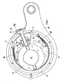
- Eccentric E can be made integral in rotation, alternatively and upon command, with connecting rod B or with ring A, precisely by shifting a key slider Q, slidable in a radial direction with respect to shaft S along guiding means G which are integral with eccentric E.
- mechanic control means are capable of radially shifting slider Q into an external position, uncoupling said slider from ring A, in contrast to the action of return spring means of slider Q into an internal position (shown in fig. 1) of coupling into matching seats I formed in diametrically opposite positions on ring A.
- Electromagnetic means (not shown) act on the external end Q E of slider Q in order to maintain the same in the external position into which it is shifted by said mechanic control means, for a set length of time.
- two opposite levers L are hinged on guiding means G, one end of which levers is constantly kept in traction by a respective spring M anchored in a suitable position on eccentric E.
- the free ends of the two levers L are positioned below slider Q (and for this reason they are only partly visible in fig. 1) and mutually meshed so as to altogether make up a movable stop capable of elastically engage one of two opposite recesses C - provided within the rod big end in correspondence of the two possible disengagement positions of slider Q - when the slider itself is brought into its external position by said control means.
- the coupling of key slider Q with ring A can occur only when one of the two opposite seats I provided on ring A lies in correspondence of the coupling end Q I of slider Q. As a matter of fact, if at that point the electromagnetic means maintaining the slider in its external position are deactivated, the slider is recalled by the spring means coupling with a corresponding seat I of ring A.
- each frame lifts and lowers, in an alternately continuous and regular manner, as long as slider Q of the respective dobby connecting rod is permanently engaged with one of the seats I provided on ring A, while the heald frame remains stationary, in the lifted or in the lowered position, whenever slider Q is disengaged from ring A in opposition to the abovementioned spring means, while it lies in correspondence of either one of the two opposite recesses C formed in the rod big end. It is hence possible to thereby obtain any desired fabric pattern.
- the slider/ring coupling is a typical key coupling, planar and parallel, hence having only an allowance sufficient for the mutual sliding of the components.
- Such a coupling therefore requires an optimal and stable mutual positioning of the components in order to be actuated.
- it is therefore not infrequent for known devices to randomly display missed couplings of slider Q which, rather than engaging with the desired seat I of ring A, hits on the edge of said seat without engaging therewith and, during the subsequent half-rotation of shaft S, rubs rubs on the external surface of ring A until it meets the diametrically opposite seat I.
- a slider for the coupling/uncoupling of a respective connecting rod with the drive shaft of a rotary dobby for weaving looms characterised in that the coupling between the coupling end of the slider and the corresponding seats formed in said shaft, or in a ring integral therewith, is a planar-conical coupling.
- said planar-conical coupling further comprises at least a mechanical stop which determines the end stop of the slider during the coupling step before full contact between the opposite walls of the conical coupling is reached.
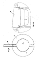
- Fig. 2 shows the detail of shaft S and of the respective driving ring A, in an enlarged scale, whereon two opposite seats I are formed for engagement with the coupling end Q I of slider Q, for the objects described above.
- Fig. 2 shows the position wherein slider Q is disengaged from ring A. In this position shaft S and driving ring A rotate without causing any shifting of connecting rod B and hence of the heald frame connected thereto.
- one of the two seats I formed on ring A lies exactly in correspondence of slider Q, as shown in fig. 3, and it is in this position that the coupling between slider and ring can be controlled, deactivating the electromagnetic means which keep the slider in its external position, so that the slider is pushed into the coupling position by the return spring means described above.
- the seat I formed on ring A has converging, inclined side walls 1, respectively parallel to the corresponding side walls 2 of the coupling end Q I of slider Q, so as to determine a planar coupling with two pairs of conical side walls ("planar-conical coupling" in the following) between the two elements when slider Q is introduced into seat I.
- walls 1 and 2 of the planar-conical coupling have a much larger circumferential clearance P than that of a conventional planar coupling, for example in the order of 1 millimetre.
- Such an increased clearance enormously reduces the risk of a missed coupling, allowing secure engagement of the coupling even at high speeds and in the presence of vibrations and/or relative micro-shifting between the two coupling elements.
- the planar-conical coupling provides high standards of coupling ease, precision, safety and graduality, further allowing to act on the inclination of the side walls of the coupling, in a predetermined range, in order to change functionality of the coupling.
- couplings with less-sharply inclined walls have improved features of graduality and safety, while couplings with more sharply inclined walls provide a wider circumferential clearance P and consequently an increased ease of engagement even in critical misalignment or vibration conditions.
- planar-conical coupling of the present invention it is necessary to bear in mind that, precisely due to the construction thereof, during the acceleration step a thrust is caused along the axial direction of slider Q due to the tangential forces acting on the inclined walls of the coupling.
- slider Q when slider Q is engaged with one of the respective seats I provided on ring A, it rotates together with shaft S and consequently simultaneously undergoes the centripetal axial force imparted by the respective retaining spring means and the axial component in the direction of expulsion of the slider - generated precisely due to coupling conicity - of the variable force resulting from the tangential acceleration of shaft S, which component is evidently the larger, the larger the inclination of the coupling walls with respect to the radial direction.
- slider Q in addition to having coupling walls 2 inclined in the way already described above, further comprises two side stops 3, formed by side ribs of slider Q, which determine the maximum possible run d of slider Q during the engagement step, through the abutment thereof on the side wall 4 of ring A surrounding seats I.
- the position of the contact edge of stops 3 is finely machined so that, when the coupling is closed, i.e.
- stops 3 are in contact with walls 4, walls 1 and 2 of the planar-conical coupling instead are not in full contact, but still have a mutual circumferential allowance F sufficient to prevent the "wedge effect" and the consequent jamming of end Q I of slider Q into seat I.
- Preferred values of allowance F lie for example in the range between 10 and 150 ⁇ m.
- the slider having a planar-conical coupling according to the present invention it is possible to remarkably improve coupling quality, even in the presence of remarkable loom speed and of vibrations, at the same time making reducing to almost negligible levels the risk of accidental disengagement of slider Q due to the centrifugal component of the acceleration forces of ring A, which component as a matter of fact acts in the direction of expulsion of the slider.
- Stops 3 and the respective abutment walls 4 are preferably treated, similarly to the other cooperating walls of the coupling, so as to have a great surface hardness, so as to guarantee a substantial absence of wear and hence a constant value of d over time, at least for the useful time expected for this type of devices.
Landscapes
- Engineering & Computer Science (AREA)
- General Engineering & Computer Science (AREA)
- Textile Engineering (AREA)
- Physics & Mathematics (AREA)
- Electromagnetism (AREA)
- Mechanical Engineering (AREA)
- Looms (AREA)
Priority Applications (4)
| Application Number | Priority Date | Filing Date | Title |
|---|---|---|---|
| DE200660003060 DE602006003060D1 (de) | 2006-02-28 | 2006-02-28 | Verbesserte Kegelkupplung der Verbindungstage in einer Rotationschaftmaschine für Webmaschinen |
| EP20060425125 EP1826301B1 (fr) | 2006-02-28 | 2006-02-28 | Couplage conique amélioré de la tige de connection dans une ratière rotative pour des métiers à tisser |
| PCT/EP2007/051813 WO2007099083A1 (fr) | 2006-02-28 | 2007-02-26 | Coulisseau d'accouplement ameliore de la bielle de connexion dans une ratiere rotative pour des metiers a tisser |
| CN2007800053685A CN101384760B (zh) | 2006-02-28 | 2007-02-26 | 改进的用于织机的旋转多臂机构中的连杆的联接滑动件 |
Applications Claiming Priority (1)
| Application Number | Priority Date | Filing Date | Title |
|---|---|---|---|
| EP20060425125 EP1826301B1 (fr) | 2006-02-28 | 2006-02-28 | Couplage conique amélioré de la tige de connection dans une ratière rotative pour des métiers à tisser |
Publications (2)
| Publication Number | Publication Date |
|---|---|
| EP1826301A1 true EP1826301A1 (fr) | 2007-08-29 |
| EP1826301B1 EP1826301B1 (fr) | 2008-10-08 |
Family
ID=36587376
Family Applications (1)
| Application Number | Title | Priority Date | Filing Date |
|---|---|---|---|
| EP20060425125 Expired - Lifetime EP1826301B1 (fr) | 2006-02-28 | 2006-02-28 | Couplage conique amélioré de la tige de connection dans une ratière rotative pour des métiers à tisser |
Country Status (4)
| Country | Link |
|---|---|
| EP (1) | EP1826301B1 (fr) |
| CN (1) | CN101384760B (fr) |
| DE (1) | DE602006003060D1 (fr) |
| WO (1) | WO2007099083A1 (fr) |
Cited By (2)
| Publication number | Priority date | Publication date | Assignee | Title |
|---|---|---|---|---|
| WO2014095338A1 (fr) * | 2012-12-20 | 2014-06-26 | MAQUET GmbH | Bras de support médical |
| US9918795B2 (en) | 2012-12-20 | 2018-03-20 | MAQUET GmbH | Instrument holder |
Citations (7)
| Publication number | Priority date | Publication date | Assignee | Title |
|---|---|---|---|---|
| US4362188A (en) | 1980-01-16 | 1982-12-07 | Maschinenfabrik Carl Zangs Aktiengesellschaft | Rotary dobby |
| US4367770A (en) | 1979-08-16 | 1983-01-11 | Staeubli Ltd. | Rotational dobby |
| EP0080547A1 (fr) * | 1981-11-30 | 1983-06-08 | GebràDer Sulzer Aktiengesellschaft | Procédé de fonctionnement d'un dispositif d'accouplement pour contrôler les cadres d'un métier à tisser et le dispositif d'accouplement lui-même |
| US4493346A (en) | 1981-01-09 | 1985-01-15 | Textilma Ag | Coupling arrangement usable in a textile machine |
| US4597417A (en) | 1983-10-07 | 1986-07-01 | Staeubli Ltd. | Lifting unit for a rotational dobby |
| US4763697A (en) | 1986-01-31 | 1988-08-16 | Fimtessile Fabbrica Italiana Macchinario Tessile S.P.A. | Mechanism to control the oscillations of the heald frame connecting rods in a rotary dobby |
| EP0525862A1 (fr) | 1991-07-25 | 1993-02-03 | NUOVOPIGNONE INDUSTRIE MECCANICHE E FONDERIA S.p.A. | Améliorations à une ratière rotative à grande vitesse |
-
2006
- 2006-02-28 EP EP20060425125 patent/EP1826301B1/fr not_active Expired - Lifetime
- 2006-02-28 DE DE200660003060 patent/DE602006003060D1/de not_active Expired - Lifetime
-
2007
- 2007-02-26 WO PCT/EP2007/051813 patent/WO2007099083A1/fr not_active Ceased
- 2007-02-26 CN CN2007800053685A patent/CN101384760B/zh active Active
Patent Citations (8)
| Publication number | Priority date | Publication date | Assignee | Title |
|---|---|---|---|---|
| US4367770A (en) | 1979-08-16 | 1983-01-11 | Staeubli Ltd. | Rotational dobby |
| US4362188A (en) | 1980-01-16 | 1982-12-07 | Maschinenfabrik Carl Zangs Aktiengesellschaft | Rotary dobby |
| US4493346A (en) | 1981-01-09 | 1985-01-15 | Textilma Ag | Coupling arrangement usable in a textile machine |
| EP0080547A1 (fr) * | 1981-11-30 | 1983-06-08 | GebràDer Sulzer Aktiengesellschaft | Procédé de fonctionnement d'un dispositif d'accouplement pour contrôler les cadres d'un métier à tisser et le dispositif d'accouplement lui-même |
| US4597417A (en) | 1983-10-07 | 1986-07-01 | Staeubli Ltd. | Lifting unit for a rotational dobby |
| US4763697A (en) | 1986-01-31 | 1988-08-16 | Fimtessile Fabbrica Italiana Macchinario Tessile S.P.A. | Mechanism to control the oscillations of the heald frame connecting rods in a rotary dobby |
| EP0234321B1 (fr) | 1986-01-31 | 1989-11-08 | FIMTESSILE FABBRICA ITALIANA MACCHINARIO TESSILE S.p.A. | Mécanisme de commande des oscillations des bielles reliées aux lames dans une ratière rotative |
| EP0525862A1 (fr) | 1991-07-25 | 1993-02-03 | NUOVOPIGNONE INDUSTRIE MECCANICHE E FONDERIA S.p.A. | Améliorations à une ratière rotative à grande vitesse |
Cited By (6)
| Publication number | Priority date | Publication date | Assignee | Title |
|---|---|---|---|---|
| WO2014095338A1 (fr) * | 2012-12-20 | 2014-06-26 | MAQUET GmbH | Bras de support médical |
| CN104755040A (zh) * | 2012-12-20 | 2015-07-01 | 迈柯唯有限公司 | 医疗的保持臂 |
| KR20150083101A (ko) * | 2012-12-20 | 2015-07-16 | 마쿠에트 게엠베하 | 의료용 홀딩 암 |
| CN104755040B (zh) * | 2012-12-20 | 2017-06-16 | 迈柯唯有限公司 | 医疗的保持臂 |
| US9918795B2 (en) | 2012-12-20 | 2018-03-20 | MAQUET GmbH | Instrument holder |
| US10072793B2 (en) | 2012-12-20 | 2018-09-11 | MAQUET GmbH | Medical holding arm |
Also Published As
| Publication number | Publication date |
|---|---|
| WO2007099083A1 (fr) | 2007-09-07 |
| EP1826301B1 (fr) | 2008-10-08 |
| CN101384760A (zh) | 2009-03-11 |
| DE602006003060D1 (de) | 2008-11-20 |
| CN101384760B (zh) | 2011-04-13 |
Similar Documents
| Publication | Publication Date | Title |
|---|---|---|
| EP1826301B1 (fr) | Couplage conique amélioré de la tige de connection dans une ratière rotative pour des métiers à tisser | |
| SE440541B (sv) | Sperrsynkronisering for vexlingsanordningar i vexellador | |
| KR100418081B1 (ko) | 제직기용로터리도비및,그것을구비한제직기 | |
| US4444225A (en) | Rotating dobbies | |
| JP4405198B2 (ja) | 回転ドビー | |
| KR101431647B1 (ko) | 회전식 도비, 이러한 도비를 포함하는 직기, 및 이러한도비를 제어하는 방법 | |
| JPS6323296B2 (fr) | ||
| EP0466234B1 (fr) | Dispositif de commande pour ratières rotatives à très grande vitesse | |
| SU1114345A3 (ru) | Ротационна ремизоподъемна каретка ткацкого станка | |
| US4646788A (en) | Rotary dobby | |
| JPH0327652B2 (fr) | ||
| US4643231A (en) | Rotary dobby | |
| SU414798A3 (fr) | ||
| US4730641A (en) | Rotational dobby | |
| US4763697A (en) | Mechanism to control the oscillations of the heald frame connecting rods in a rotary dobby | |
| US2443593A (en) | Clutch for spinning buckets | |
| SU1009280A3 (ru) | Ротационна ремизоподъемна каретка дл ткацкого станка | |
| SU978736A3 (ru) | Ротационна ремизоподъемна каретка ткацкого станка | |
| US4614211A (en) | Dobby | |
| JPH0143050B2 (fr) | ||
| JPH0361775B2 (fr) | ||
| US6059552A (en) | Hydraulic vane machine | |
| US4523915A (en) | Reverse weaving mechanisms | |
| JPS6245748A (ja) | 織機のひ口形成装置のための昇降ビ−ム | |
| EP1191137B1 (fr) | Accouplement pour la connexion rotative des arbres d'entraînement des ratières et des métiers à tisser |
Legal Events
| Date | Code | Title | Description |
|---|---|---|---|
| PUAI | Public reference made under article 153(3) epc to a published international application that has entered the european phase |
Free format text: ORIGINAL CODE: 0009012 |
|
| AK | Designated contracting states |
Kind code of ref document: A1 Designated state(s): AT BE BG CH CY CZ DE DK EE ES FI FR GB GR HU IE IS IT LI LT LU LV MC NL PL PT RO SE SI SK TR |
|
| AX | Request for extension of the european patent |
Extension state: AL BA HR MK YU |
|
| 17P | Request for examination filed |
Effective date: 20070907 |
|
| 17Q | First examination report despatched |
Effective date: 20071011 |
|
| RTI1 | Title (correction) |
Free format text: IMPROVED CONICAL COUPLING OF THE CONNECTING ROD IN A ROTARY DOBBY FOR WEAVING LOOMS |
|
| GRAP | Despatch of communication of intention to grant a patent |
Free format text: ORIGINAL CODE: EPIDOSNIGR1 |
|
| AKX | Designation fees paid |
Designated state(s): BE CH DE FR IT LI TR |
|
| GRAS | Grant fee paid |
Free format text: ORIGINAL CODE: EPIDOSNIGR3 |
|
| GRAA | (expected) grant |
Free format text: ORIGINAL CODE: 0009210 |
|
| AK | Designated contracting states |
Kind code of ref document: B1 Designated state(s): BE CH DE FR IT LI TR |
|
| REG | Reference to a national code |
Ref country code: CH Ref legal event code: EP |
|
| REF | Corresponds to: |
Ref document number: 602006003060 Country of ref document: DE Date of ref document: 20081120 Kind code of ref document: P |
|
| REG | Reference to a national code |
Ref country code: CH Ref legal event code: NV Representative=s name: PATENTANWAELTE SCHAAD, BALASS, MENZL & PARTNER AG |
|
| PLBE | No opposition filed within time limit |
Free format text: ORIGINAL CODE: 0009261 |
|
| STAA | Information on the status of an ep patent application or granted ep patent |
Free format text: STATUS: NO OPPOSITION FILED WITHIN TIME LIMIT |
|
| 26N | No opposition filed |
Effective date: 20090709 |
|
| PGFP | Annual fee paid to national office [announced via postgrant information from national office to epo] |
Ref country code: FR Payment date: 20130228 Year of fee payment: 8 |
|
| REG | Reference to a national code |
Ref country code: FR Ref legal event code: ST Effective date: 20141031 |
|
| PG25 | Lapsed in a contracting state [announced via postgrant information from national office to epo] |
Ref country code: FR Free format text: LAPSE BECAUSE OF NON-PAYMENT OF DUE FEES Effective date: 20140228 |
|
| PGFP | Annual fee paid to national office [announced via postgrant information from national office to epo] |
Ref country code: DE Payment date: 20160226 Year of fee payment: 11 Ref country code: CH Payment date: 20160226 Year of fee payment: 11 |
|
| REG | Reference to a national code |
Ref country code: DE Ref legal event code: R119 Ref document number: 602006003060 Country of ref document: DE |
|
| REG | Reference to a national code |
Ref country code: CH Ref legal event code: PL |
|
| PG25 | Lapsed in a contracting state [announced via postgrant information from national office to epo] |
Ref country code: LI Free format text: LAPSE BECAUSE OF NON-PAYMENT OF DUE FEES Effective date: 20170228 Ref country code: CH Free format text: LAPSE BECAUSE OF NON-PAYMENT OF DUE FEES Effective date: 20170228 |
|
| PG25 | Lapsed in a contracting state [announced via postgrant information from national office to epo] |
Ref country code: DE Free format text: LAPSE BECAUSE OF NON-PAYMENT OF DUE FEES Effective date: 20170901 |
|
| PGFP | Annual fee paid to national office [announced via postgrant information from national office to epo] |
Ref country code: TR Payment date: 20240214 Year of fee payment: 19 Ref country code: IT Payment date: 20240222 Year of fee payment: 19 Ref country code: BE Payment date: 20240227 Year of fee payment: 19 |
|
| REG | Reference to a national code |
Ref country code: BE Ref legal event code: MM Effective date: 20250228 |
|
| PG25 | Lapsed in a contracting state [announced via postgrant information from national office to epo] |
Ref country code: IT Free format text: LAPSE BECAUSE OF NON-PAYMENT OF DUE FEES Effective date: 20250228 |
|
| PG25 | Lapsed in a contracting state [announced via postgrant information from national office to epo] |
Ref country code: BE Free format text: LAPSE BECAUSE OF NON-PAYMENT OF DUE FEES Effective date: 20250228 |