EP1826345A2 - Schloss - Google Patents
Schloss Download PDFInfo
- Publication number
- EP1826345A2 EP1826345A2 EP06126972A EP06126972A EP1826345A2 EP 1826345 A2 EP1826345 A2 EP 1826345A2 EP 06126972 A EP06126972 A EP 06126972A EP 06126972 A EP06126972 A EP 06126972A EP 1826345 A2 EP1826345 A2 EP 1826345A2
- Authority
- EP
- European Patent Office
- Prior art keywords
- lock
- follower
- case
- locking device
- lock according
- Prior art date
- Legal status (The legal status is an assumption and is not a legal conclusion. Google has not performed a legal analysis and makes no representation as to the accuracy of the status listed.)
- Granted
Links
Images



Classifications
-
- E—FIXED CONSTRUCTIONS
- E05—LOCKS; KEYS; WINDOW OR DOOR FITTINGS; SAFES
- E05C—BOLTS OR FASTENING DEVICES FOR WINGS, SPECIALLY FOR DOORS OR WINDOWS
- E05C9/00—Arrangements of simultaneously actuated bolts or other securing devices at well-separated positions on the same wing
- E05C9/04—Arrangements of simultaneously actuated bolts or other securing devices at well-separated positions on the same wing with two sliding bars moved in opposite directions when fastening or unfastening
- E05C9/046—Arrangements of simultaneously actuated bolts or other securing devices at well-separated positions on the same wing with two sliding bars moved in opposite directions when fastening or unfastening with two interconnected mechanisms each driving one rod
-
- E—FIXED CONSTRUCTIONS
- E05—LOCKS; KEYS; WINDOW OR DOOR FITTINGS; SAFES
- E05C—BOLTS OR FASTENING DEVICES FOR WINGS, SPECIALLY FOR DOORS OR WINDOWS
- E05C9/00—Arrangements of simultaneously actuated bolts or other securing devices at well-separated positions on the same wing
- E05C9/04—Arrangements of simultaneously actuated bolts or other securing devices at well-separated positions on the same wing with two sliding bars moved in opposite directions when fastening or unfastening
- E05C9/047—Arrangements of simultaneously actuated bolts or other securing devices at well-separated positions on the same wing with two sliding bars moved in opposite directions when fastening or unfastening comprising key-operated locks, e.g. a lock cylinder to drive auxiliary deadbolts or latch bolts
-
- E—FIXED CONSTRUCTIONS
- E05—LOCKS; KEYS; WINDOW OR DOOR FITTINGS; SAFES
- E05B—LOCKS; ACCESSORIES THEREFOR; HANDCUFFS
- E05B15/00—Other details of locks; Parts for engagement by bolts of fastening devices
- E05B15/16—Use of special materials for parts of locks
- E05B15/1635—Use of special materials for parts of locks of plastics materials
- E05B2015/1664—Use of special materials for parts of locks of plastics materials for lock housing
Definitions
- the invention relates to a lock, in particular a mortise lock, for a window, a French window or the like with a biased out of a lock case latch with a locking device, with a pivotable in two directions follower, wherein the follower in a pivoting direction for retracting the trap and for unlocking the locking device and is formed in the opposite direction to lock the locking device, and with two drive rods of the locking device.
- Such a lock is from the DE 698 07 801 T2 known.
- the follower is connected via a first row of teeth with a drive rod and a second row of teeth and a gearbox with the other drive rod.
- the drive of the two drive rods designed very complex.
- the invention is based on the problem of developing a lock of the type mentioned so that it is particularly simple in design and inexpensive to manufacture.
- the locking device comprises two levers mounted in the lock case, that the levers are each coupled to a drive rod and that a slider adjustable by the follower has in each case a bearing point on the levers.
- the follower does not require any rows of teeth for driving the drive rods.
- the levers can be easily connected to the lock case, the drive rods and the slide and are particularly easy to install. Therefore, the risk of incorrect installation of the lock according to the invention is kept particularly low. Furthermore, the lock according to the invention can be manufactured particularly cost-effectively by the simple assembly.
- the structural complexity for the opposite drive of the drive rods can be kept particularly low according to an advantageous embodiment of the invention, when the bearing point of the slide on one lever between its storage on the lock case and the coupling to the drive rod and the bearing point of the slider on the other lever is seen behind the storage on the lock case seen from the coupling of the drive rod.
- the ends of the drive rods facing away from the lock according to the invention can directly lock the window or the French window. In the simplest case, therefore, the locking device requires no additional lock to be mounted.
- a backlash of the follower against the locking device designed in accordance with another advantageous embodiment of the invention structurally particularly simple, when the actuator arms of the pusher are spaced from each other. This backlash allows the pusher nut can be moved back to its original position both locked and unlocked latch device.
- the position of the legs in the lock according to the invention can be easily determined when the legs rest against walls of the lock case. This design also reliably prevents faulty mounting of the lock according to the invention.
- the lock contributes, when a case retracting lever is pivotally mounted in the lock case and is guided up to a Fallenstellarm the follower and when the trap is supported on a central region of the Fallenretzugshebels.
- the structural complexity for locking the lock according to the invention can be kept particularly low when an internal bolt with locked locking device facing a recess of the slide and protrudes into a receptacle for a lock cylinder.
- the lock according to the invention can be locked, by means of the lock cylinder, the inner latch is moved into the recess of the slider inside.
- the lock according to the invention can be manufactured particularly cost-effectively and yet has a high stability when the lock case is made of plastic and supported by webs, arranged parallel to the pivot axis of the follower has walls.
- Figure 1 shows a lock with a lock case 1 and with a biased out of the lock case 1 case 2 in an unlocked position.
- the lock has a handle provided for connection to a handle, not shown, handle 3 and a receptacle 4 for a lock cylinder. To simplify the drawing of the lock cylinder only a cam 5 is shown.
- the lock case 1 is made of plastic and has supported by webs 6, parallel to the pivot axis of the follower 3 arranged walls. 7
- two drive rods 8, 9 of a locking device 10 are guided displaceably and each coupled to a lever 11, 12.
- the levers 11, 12 are pivotally mounted in the lock case 1 and connected to a slider 13.
- the drive rods 8, 9 can for example drive from the lock case 1 arranged additional locks.
- the slider 13 has a protruding between two actuating arms 15, 16 of the follower 3 protrusion 14.
- the actuating arms 15, 16 of the follower 3 are spaced from each other.
- the pusher nut 3 also has a Fallenstellarm 17, which faces a free end of a Fallenretzugshebels 18.
- the latch retracting lever 18 is pivotally mounted in the lock case 1.
- the case 2 is biased by a coil spring 19 in the position shown and is supported in a central region of the case retracting lever 18 from.
- An arranged in the lock case 1, designed as a leg spring spring element 20 has two legs 21, 22.
- the legs 21, 22 are supported on flanks 23, 24 of the follower 3 and are held by the walls 7 of the lock case 1.
- the legs 21, 22 of the spring element 20 cause the follower 3 is pivoted back to a rotation at any time back to the illustrated basic position.
- the cam 5 of the lock cylinder acts with a displaceably guided in the lock case 1 inner latch 25 together.
- a recess 26 in the slider 13 has the same width as one end of the inner bolt 25.
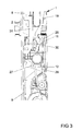
- FIG. 3 shows the partial area of the lock shown in FIG. 2 after removal of the pusher nut 3 and of the slide 13.
- one lever 12 has a central bearing 27 in the slide 13 shown in FIG. 2 and one on the drive rod 9 facing away from a storage 28 in the lock case 1 has.
- the other of the levers 11 has, conversely, a bearing 29 arranged at one end with the slider 13 and a central bearing 30 in the lock case 1.
- the bearings 27, 29 each have a longitudinal direction of the lever 11, 12 facing game.
- the other free ends of the levers 11, 12 are coupled directly or via an intermediate slide 31 with the drive rods 8, 9. This ensures that during a movement of the slider 13 shown in Figure 2, the levers 11, 12 are pivoted in opposite directions and thus the drive rods 8, 9 are moved in opposite directions.
Landscapes
- Engineering & Computer Science (AREA)
- Mechanical Engineering (AREA)
- Lock And Its Accessories (AREA)
- Window Of Vehicle (AREA)
- Closing And Opening Devices For Wings, And Checks For Wings (AREA)
Abstract
Description
- Die Erfindung betrifft ein Schloss, insbesondere ein Einsteckschloss, für ein Fenster, eine Fenstertür oder dergleichen mit einer aus einem Schlosskasten heraus vorgespannten Falle mit einer Riegeleinrichtung, mit einer in zwei Richtungen schwenkbaren Drückernuss, wobei die Drückernuss in der einen Schwenkrichtung zum Zurückziehen der Falle und zur Entriegelung der Riegeleinrichtung und in der entgegengesetzten Richtung zur Verriegelung der Riegeleinrichtung ausgebildet ist, und mit zwei Treibstangen der Riegeleinrichtung.
- Ein solches Schloss ist aus der
DE 698 07 801 T2 bekannt. Bei diesem Schloss ist die Drückernuss über eine erste Zahnreihe mit einen Treibstange und über eine zweite Zahnreihe und ein Getriebe mit der anderen Treibstange verbunden. Hierdurch gestaltet sich der Antrieb der beiden Treibstangen sehr aufwändig. - Der Erfindung liegt das Problem zugrunde ein Schloss der eingangs genannten Art so weiterzubilden, dass es besonders einfach aufgebaut und kostengünstig zu fertigen ist.
- Dieses Problem wird erfindungsgemäß dadurch gelöst, dass die Riegeleinrichtung zwei in dem Schlosskasten gelagerte Hebel aufweist, dass die Hebel jeweils mit einer Treibstange gekoppelt sind und dass ein von der Drückernuss verstellbarer Schieber jeweils eine Lagerstelle an den Hebeln aufweist.
- Durch diese Gestaltung benötigt die Drückernuss keine Zahnreihen zum Antrieb der Treibstangen. Die Hebel lassen sich einfach mit dem Schlosskasten, den Treibstangen und dem Schieber verbinden und sind besonders einfach montierbar. Daher wird die Gefahr einer fehlerhaften Montage des erfindungsgemäßen Schlosses besonders gering gehalten. Weiterhin lässt sich das erfindungsgemäße Schloss durch die einfache Montage besonders kostengünstig fertigen.
- Der bauliche Aufwand zum gegenläufigen Antrieb der Treibstangen lässt sich gemäß einer vorteilhaften Weiterbildung der Erfindung besonders gering halten, wenn die Lagerstelle des Schiebers an dem einen Hebel zwischen dessen Lagerung an dem Schlosskasten und der Koppelung an der Treibstange und die Lagerstelle des Schiebers an dem anderen Hebel von der Koppelung der Treibstange aus gesehen hinter der Lagerung an dem Schlosskasten angeordnet ist. Durch diese Gestaltung können die dem erfindungsgemäßen Schloss abgewandten Enden der Treibstangen unmittelbar das Fenster oder die Fenstertür verriegeln. Im einfachsten Fall benötigt daher die Riegeleinrichtung kein zusätzlich zu montierendes Nebenschloss.
- Die Betätigung des Schiebers über die Drückernuss gestaltet sich gemäß einer anderen vorteilhaften Weiterbildung der Erfindung konstruktiv besonders einfach, wenn der Schieber einen Vorsprung und die Drückernuss dem Vorsprung gegenüberstehende Stellarme aufweist.
- Ein Totgang der Drückernuss gegenüber der Riegeleinrichtung gestaltet sich gemäß einer anderen vorteilhaften Weiterbildung der Erfindung konstruktiv besonders einfach, wenn die Stellarme der Drückernuss voneinander beabstandet sind. Dieser Totgang ermöglicht, dass die Drückernuss sowohl bei verriegelter als auch bei entriegelter Riegeleinrichtung wieder in ihre Ausgangslage zurück bewegt werden kann.
- Der bauliche Aufwand zur Rückbewegung der Drückernuss in die Grundstellung lässt sich gemäß einer anderen vorteilhaften Weiterbildung der Erfindung besonders gering halten, wenn in dem Schlosskasten eine Schenkelfeder mit zwei auf die Drückernuss zu ragenden Schenkeln gehalten ist und wenn jeder der Schenkel an einer Flanke der Drückernuss anliegt.
- Die Lage der Schenkel in dem erfindungsgemäßen Schloss lässt sich einfach festlegen, wenn die Schenkel an Wandungen des Schlosskastens anliegen. Durch diese Gestaltung wird zudem eine fehlerhafte Montage des erfindungsgemäßen Schlosses zuverlässig vermieden.
- Zur weiteren Vereinfachung des Aufbaus des erfindungsgemäßen Schlosses trägt es bei, wenn ein Fallenrückzugshebel in dem Schlosskasten schwenkbar gelagert ist und bis zu einem Fallenstellarm der Drückernuss geführt ist und wenn sich die Falle an einem mittleren Bereich des Fallenrückzugshebels abstützt.
- Der bauliche Aufwand zur Verriegelung des erfindungsgemäßen Schlosses lässt sich besonders gering halten, wenn ein Innenriegel bei verriegelter Riegeleinrichtung einer Ausnehmung des Schiebers gegenübersteht und in eine Aufnahme für einen Schließzylinder hineinragt. Durch diese Gestaltung lässt sich das erfindungsgemäße Schloss verriegeln, indem mittels des Schließzylinders der Innenriegel in die Ausnehmung des Schiebers hinein bewegt wird.
- Das erfindungsgemäße Schloss lässt sich besonders kostengünstig fertigen und weist dennoch eine hohe Stabilität auf, wenn der Schlosskasten aus Kunststoff gefertigt ist und von Stegen abgestützte, parallel zur Schwenkachse der Drückernuss angeordnete Wandungen aufweist.
- Die Erfindung lässt zahlreiche Ausführungsformen zu. Zur weiteren Verdeutlichung ihres Grundprinzips ist eine davon in der Zeichnung dargestellt und wird nachfolgend beschrieben. Diese zeigt in
- Fig. 1
- ein erfindungsgemäßes Schloss in entriegelter Stellung,
- Fig. 2
- stark vergrößert einen Teilbereich des erfindungsgemäßen Schlosses aus Figur 1,
- Fig. 3
- den in Figur 2 dargestellten Teilbereich des erfindungsgemäßen Schlosses nach Entfernung eines Schiebers,
- Fig. 4
- das erfindungsgemäße Schloss aus Figur 1 in verriegelter Stellung.
- Figur 1 zeigt ein Schloss mit einem Schlosskasten 1 und mit einer aus dem Schlosskasten 1 heraus vorgespannten Falle 2 in einer entriegelten Stellung. Das Schloss weist eine zur Verbindung mit einer nicht dargestellten Handhabe vorgesehene Drückernuss 3 und eine Aufnahme 4 für einen Schließzylinder auf. Zur Vereinfachung der Zeichnung ist von dem Schließzylinder nur ein Schließbart 5 dargestellt. Der Schlosskasten 1 ist aus Kunststoff gefertigt und hat von Stegen 6 abgestützte, parallel zur Schwenkachse der Drückernuss 3 angeordnete Wandungen 7.
- In dem Schlosskasten sind zwei Treibstangen 8, 9 einer Riegeleinrichtung 10 verschieblich geführt und jeweils mit einem Hebel 11, 12 gekoppelt. Die Hebel 11, 12 sind schwenkbar in dem Schlosskasten 1 gelagert und mit einem Schieber 13 verbunden. Die Treibstangen 8, 9 können beispielsweise von dem Schlosskasten 1 entfernt angeordnete Zusatzschlösser antreiben. Der Schieber 13 weist einen zwischen zwei Stellarmen 15, 16 der Drückernuss 3 ragenden Vorsprung 14 auf. Die Stellarme 15, 16 der Drückernuss 3 sind voneinander beabstandet.
- Die Drückernuss 3 weist zudem einen Fallenstellarm 17 auf, welcher einem freien Ende eines Fallenrückzugshebels 18 gegenübersteht. Der Fallenrückzugshebel 18 ist in dem Schlosskasten 1 schwenkbar gelagert. Die Falle 2 ist von einer Wendelfeder 19 in die dargestellte Lage vorgespannt und stützt sich in einem mittleren Bereich des Fallenrückzugshebels 18 ab.
- Ein in dem Schlosskasten 1 angeordnetes, als Schenkelfeder ausgebildetes Federelement 20 weist zwei Schenkel 21, 22 auf. Die Schenkel 21, 22 stützen sich an Flanken 23, 24 der Drückernuss 3 ab und werden von den Wandungen 7 des Schlosskastens 1 gehalten. Die Schenkel 21, 22 des Federelementes 20 bewirken, dass die Drückernuss 3 nach einer Verdrehung jederzeit wieder in die dargestellte Grundstellung zurück geschwenkt wird.
- Der Schließbart 5 des Schließzylinders wirkt mit einem in dem Schlosskasten 1 verschieblich geführten Innenriegel 25 zusammen. Eine Ausnehmung 26 in dem Schieber 13 weist die selbe Breite auf, wie ein Ende des Innenriegels 25.
- Die mit der Drückernuss 3 zusammenwirkenden Bauteile des Schlosses aus Figur 1 sind vergrößert in Figur 2 dargestellt. Figur 3 zeigt den in Figur 2 dargestellten Teilbereich des Schlosses nach der Entfernung der Drückernuss 3 und des Schiebers 13. Hierbei ist zu erkennen, dass der eine Hebel 12 eine mittige Lagerstelle 27 in dem in Figur 2 dargestellten Schieber 13 und eine an dem der Treibstange 9 abgewandten Ende eine Lagerung 28 in dem Schlosskasten 1 hat. Der andere der Hebel 11 weist umgekehrt eine an einem Ende angeordnete Lagerstelle 29 mit dem Schieber 13 und eine mittige Lagerung 30 in dem Schlosskasten 1 auf. Die Lagerstellen 27, 29 weisen jeweils ein in Längsrichtung der Hebel 11, 12 weisendes Spiel auf. Die anderen freien Enden der Hebel 11, 12 sind direkt oder über einen Zwischenschieber 31 mit den Treibstangen 8, 9 gekoppelt. Hierdurch wird sichergestellt, dass bei einer Bewegung des in Figur 2 dargestellten Schiebers 13 die Hebel 11, 12 gegensinnig verschwenkt und damit die Treibstangen 8, 9 gegensinnig verschoben werden.
- Wenn man ausgehend von der in Figur 1 dargestellten Stellung die Drückernuss 3 im Uhrzeigersinn verdreht, wird der Fallenrückzugshebel 18 über den Fallenstellarm 17 der Drückernuss 3 ausgelenkt und damit die Falle 2 gegen die Kraft der Wendelfeder 19 zurückgezogen. Dabei wird einer der Schenkel 21 des Federelementes 20 ausgelenkt. Nach einem Loslassen der Drückernuss 3 gelangen die Falle 2 und die Drückernuss 3 durch die Kräfte der Wendelfeder 19 und des Federelementes 20 wieder in die in Figur 1 dargestellte Lage zurück.
- Verschenkt man die Drückernuss 3 gegen den Uhrzeigersinn, nimmt einer der Stellarme 15 den Vorsprung 14 des Schiebers 13 mit. Hierdurch werden die Hebel 11, 12 gegensinnig ausgelenkt und damit die Treibstangen 8, 9 in eine verriegelte Stellung des Schlosses verschoben. Dabei wird einer der Schenkel 22 des Federelementes 20 ausgelenkt und bewegt die Drückernuss 3 anschließend wieder in die Grundstellung zurück. Da die Stellarme 15, 16 der Drückernuss 3 voneinander beabstandet sind, verbleibt der Schieber 13 und damit die Treibstangen 8, 9 in der verriegelten Stellung. In dieser Stellung des Schiebers 13 lässt sich der Innenriegel 25 mittels des Schließbartes 5 des Schließzylinders in die Ausnehmung 26 des Schiebers 13 bewegen und das Schloss verriegeln. Diese Stellung ist in Figur 4 dargestellt. Der Vorsprung 14 des Schiebers 13 befindet sich nun an dem anderen Stellarm 16 der Drückernuss 3. Nach einer Herausbewegung des Innenriegels 25 aus der Ausnehmung 26 des Schiebers 13 lässt sich ausgehend von der in Figur 4 dargestellten Stellung die Drückernuss 3 zur Entriegelung wieder im Uhrzeigersinn verschwenken. Dabei wird, wie oben beschrieben, die Falle 2 zurückgezogen und gleichzeitig der Schieber 13 und damit die Treibstangen 8, 9 in die in Figur 1 dargestellte, entriegelte Stellung bewegt.
Claims (9)
- Schloss, insbesondere Einsteckschloss, für ein Fenster, eine Fenstertür oder dergleichen mit einer aus einem Schlosskasten heraus vorgespannten Falle mit einer Riegeleinrichtung, mit einer in zwei Richtungen schwenkbaren Drückernuss, wobei die Drückernuss in der einen Schwenkrichtung zum Zurückziehen der Falle und zur Entriegelung der Riegeleinrichtung und in der entgegengesetzten Richtung zur Verriegelung der Riegeleinrichtung ausgebildet ist, und mit zwei Treibstangen der Riegeleinrichtung, dadurch gekennzeichnet, dass die Riegeleinrichtung (10) zwei in dem Schlosskasten (1) gelagerte Hebel (11, 12) aufweist, dass die Hebel (11, 12) jeweils direkt oder indirekt mit einer Treibstange (8, 9) gekoppelt sind und dass ein von der Drückernuss (3) verstellbarer Schieber (13) jeweils eine Lagerstelle (27, 29) an den Hebeln (11, 12) aufweist.
- Schloss nach Anspruch 1, dadurch gekennzeichnet, dass die Lagerstelle (27) des Schiebers (13) an dem einen Hebel (12) zwischen dessen Lagerung (28) an dem Schlosskasten (1) und der Koppelung an der Treibstange (9) und die Lagerstelle (29) des Schiebers (13) an dem anderen Hebel (11) von der Koppelung der Treibstange (8) aus gesehen hinter der Lagerung (30) an dem Schlosskasten (1) angeordnet ist.
- Schloss nach Anspruch 1 oder 2, dadurch gekennzeichnet, dass der Schieber (13) einen Vorsprung (14) und die Drückernuss (3) dem Vorsprung (14) gegenüberstehende Stellarme (15, 16) aufweist.
- Schloss nach Anspruch 3, dadurch gekennzeichnet, dass die Stellarme (15, 16) der Drückernuss (3) voneinander beabstandet sind.
- Schloss nach einem der vorhergehenden Ansprüche, dadurch gekennzeichnet, dass in dem Schlosskasten (1) eine Schenkelfeder mit zwei auf die Drückernuss (3) zu ragenden Schenkeln (21, 22) gehalten ist und dass jeder der Schenkel (21, 22) an einer Flanke (23, 24) der Drückernuss (3) anliegt.
- Schloss nach Anspruch 5, dadurch gekennzeichnet, dass die Schenkel (21, 22) an Wandungen (7) des Schlosskastens (1) anliegen.
- Schloss nach einem der vorhergehenden Ansprüche, dadurch gekennzeichnet, dass ein Fallenrückzugshebel (18) in dem Schlosskasten (1) schwenkbar gelagert ist und bis zu einem Fallenstellarm (17) der Drückernuss (3) geführt ist und dass sich die Falle (2) an einem mittleren Bereich des Fallenrückzugshebels (18) abstützt.
- Schloss nach einem der vorhergehenden Ansprüche, dadurch gekennzeichnet, dass ein Innenriegel (25) bei verriegelter Riegeleinrichtung (10) einer Ausnehmung (26) des Schiebers (13) gegenübersteht und in eine Aufnahme (4) für einen Schließzylinder hineinragt.
- Schloss nach einem der vorhergehenden Ansprüche, dadurch gekennzeichnet, dass der Schlosskasten (1) aus Kunststoff gefertigt ist und von Stegen (6) abgestützte, parallel zur Schwenkachse der Drückernuss (3) angeordnete Wandungen (7) aufweist.
Applications Claiming Priority (1)
| Application Number | Priority Date | Filing Date | Title |
|---|---|---|---|
| DE200610000091 DE102006000091A1 (de) | 2006-02-24 | 2006-02-24 | Schloss |
Publications (3)
| Publication Number | Publication Date |
|---|---|
| EP1826345A2 true EP1826345A2 (de) | 2007-08-29 |
| EP1826345A3 EP1826345A3 (de) | 2011-08-10 |
| EP1826345B1 EP1826345B1 (de) | 2014-09-10 |
Family
ID=38179769
Family Applications (1)
| Application Number | Title | Priority Date | Filing Date |
|---|---|---|---|
| EP20060126972 Active EP1826345B1 (de) | 2006-02-24 | 2006-12-22 | Schloss |
Country Status (2)
| Country | Link |
|---|---|
| EP (1) | EP1826345B1 (de) |
| DE (1) | DE102006000091A1 (de) |
Citations (2)
| Publication number | Priority date | Publication date | Assignee | Title |
|---|---|---|---|---|
| DE259762C (de) | ||||
| DE69807801T2 (de) | 1997-08-01 | 2003-07-10 | Vachette, Paris | Verriegelungsvorrichtung, insbesondere Einsteckschloss für den Flügel einer Tür oder eines Fensters |
Family Cites Families (7)
| Publication number | Priority date | Publication date | Assignee | Title |
|---|---|---|---|---|
| DE688457C (de) * | 1936-05-30 | 1940-02-23 | Kiekert Soehne Arn | Verschluss fuer Kraftwagentueren u. dgl. |
| GB8431227D0 (en) * | 1984-12-11 | 1985-01-23 | Parkes Josiah & Sons Ltd | Multi-point locks |
| GB8802884D0 (en) * | 1988-02-09 | 1988-03-09 | Yale Security Prod Ltd | Improvements in/relating to locks |
| AT402835B (de) * | 1994-12-21 | 1997-09-25 | Roto Frank Eisenwaren | Drückerbetätigbares mehrriegelschloss |
| DE29701070U1 (de) * | 1997-01-22 | 1998-05-20 | Ferco International Ferrures et Serrures de Bâtiment S.A., Reding | Schloß mit Falle für Tür oder Fenster |
| GB0005669D0 (en) * | 2000-03-10 | 2000-05-03 | Over Ian E | Improvement in or relating to locking systems |
| DE202005002908U1 (de) * | 2005-02-22 | 2005-06-16 | Bks Gmbh | Einsteckschloß |
-
2006
- 2006-02-24 DE DE200610000091 patent/DE102006000091A1/de not_active Withdrawn
- 2006-12-22 EP EP20060126972 patent/EP1826345B1/de active Active
Patent Citations (2)
| Publication number | Priority date | Publication date | Assignee | Title |
|---|---|---|---|---|
| DE259762C (de) | ||||
| DE69807801T2 (de) | 1997-08-01 | 2003-07-10 | Vachette, Paris | Verriegelungsvorrichtung, insbesondere Einsteckschloss für den Flügel einer Tür oder eines Fensters |
Also Published As
| Publication number | Publication date |
|---|---|
| EP1826345B1 (de) | 2014-09-10 |
| DE102006000091A1 (de) | 2007-08-30 |
| EP1826345A3 (de) | 2011-08-10 |
Similar Documents
| Publication | Publication Date | Title |
|---|---|---|
| EP1867817B1 (de) | Treibstangenverschluss | |
| WO1996019630A1 (de) | Drückerbetätigbares mehrriegelschloss | |
| DE102008018623A1 (de) | Antriebselement für einen Beschlag | |
| EP2980340B1 (de) | Treibstangenschloss | |
| EP1826345B1 (de) | Schloss | |
| AT516517B1 (de) | Schloss | |
| EP1739257B1 (de) | Schloss | |
| EP3315695B1 (de) | Schloss | |
| EP2290180B1 (de) | Schloss | |
| EP2085543B1 (de) | Schloss | |
| EP4379173B1 (de) | Schliesszylinder | |
| EP3064679B1 (de) | Schloss | |
| DE2845277A1 (de) | Treibstangenschloss mit falle | |
| DE19750966A1 (de) | Schloß | |
| EP2998494B1 (de) | Treibstangenschloss | |
| EP3192950B1 (de) | Schloss | |
| EP3521538B1 (de) | Schloss mit einem fallenriegel | |
| EP2927397B1 (de) | Einsteckschloss | |
| DE383759C (de) | Sicherheitstuerschloss | |
| AT516516B1 (de) | Schloss | |
| EP2987929B1 (de) | Treibstangenschloss | |
| DE20312319U1 (de) | Schloß | |
| EP3498943A1 (de) | Schloss | |
| DE202005006871U1 (de) | Drehvorrichtung zum Betätigen eines Möbelschlosses | |
| DE202005007310U1 (de) | Schloss mit Rückdrücksicherung |
Legal Events
| Date | Code | Title | Description |
|---|---|---|---|
| PUAI | Public reference made under article 153(3) epc to a published international application that has entered the european phase |
Free format text: ORIGINAL CODE: 0009012 |
|
| AK | Designated contracting states |
Kind code of ref document: A2 Designated state(s): AT BE BG CH CY CZ DE DK EE ES FI FR GB GR HU IE IS IT LI LT LU LV MC NL PL PT RO SE SI SK TR |
|
| AX | Request for extension of the european patent |
Extension state: AL BA HR MK YU |
|
| PUAL | Search report despatched |
Free format text: ORIGINAL CODE: 0009013 |
|
| AK | Designated contracting states |
Kind code of ref document: A3 Designated state(s): AT BE BG CH CY CZ DE DK EE ES FI FR GB GR HU IE IS IT LI LT LU LV MC NL PL PT RO SE SI SK TR |
|
| AX | Request for extension of the european patent |
Extension state: AL BA HR MK RS |
|
| RIC1 | Information provided on ipc code assigned before grant |
Ipc: E05C 9/04 20060101AFI20110701BHEP |
|
| 17P | Request for examination filed |
Effective date: 20111103 |
|
| AKX | Designation fees paid |
Designated state(s): AT BE BG CH CY CZ DE DK EE ES FI FR GB GR HU IE IS IT LI LT LU LV MC NL PL PT RO SE SI SK TR |
|
| 17Q | First examination report despatched |
Effective date: 20130211 |
|
| GRAP | Despatch of communication of intention to grant a patent |
Free format text: ORIGINAL CODE: EPIDOSNIGR1 |
|
| INTG | Intention to grant announced |
Effective date: 20140527 |
|
| GRAS | Grant fee paid |
Free format text: ORIGINAL CODE: EPIDOSNIGR3 |
|
| GRAA | (expected) grant |
Free format text: ORIGINAL CODE: 0009210 |
|
| AK | Designated contracting states |
Kind code of ref document: B1 Designated state(s): AT BE BG CH CY CZ DE DK EE ES FI FR GB GR HU IE IS IT LI LT LU LV MC NL PL PT RO SE SI SK TR |
|
| REG | Reference to a national code |
Ref country code: GB Ref legal event code: FG4D Free format text: NOT ENGLISH |
|
| REG | Reference to a national code |
Ref country code: CH Ref legal event code: EP |
|
| REG | Reference to a national code |
Ref country code: IE Ref legal event code: FG4D Free format text: LANGUAGE OF EP DOCUMENT: GERMAN |
|
| REG | Reference to a national code |
Ref country code: AT Ref legal event code: REF Ref document number: 686798 Country of ref document: AT Kind code of ref document: T Effective date: 20141015 |
|
| REG | Reference to a national code |
Ref country code: DE Ref legal event code: R096 Ref document number: 502006013966 Country of ref document: DE Effective date: 20141023 |
|
| PG25 | Lapsed in a contracting state [announced via postgrant information from national office to epo] |
Ref country code: SE Free format text: LAPSE BECAUSE OF FAILURE TO SUBMIT A TRANSLATION OF THE DESCRIPTION OR TO PAY THE FEE WITHIN THE PRESCRIBED TIME-LIMIT Effective date: 20140910 Ref country code: LT Free format text: LAPSE BECAUSE OF FAILURE TO SUBMIT A TRANSLATION OF THE DESCRIPTION OR TO PAY THE FEE WITHIN THE PRESCRIBED TIME-LIMIT Effective date: 20140910 Ref country code: GR Free format text: LAPSE BECAUSE OF FAILURE TO SUBMIT A TRANSLATION OF THE DESCRIPTION OR TO PAY THE FEE WITHIN THE PRESCRIBED TIME-LIMIT Effective date: 20141211 Ref country code: ES Free format text: LAPSE BECAUSE OF FAILURE TO SUBMIT A TRANSLATION OF THE DESCRIPTION OR TO PAY THE FEE WITHIN THE PRESCRIBED TIME-LIMIT Effective date: 20140910 Ref country code: FI Free format text: LAPSE BECAUSE OF FAILURE TO SUBMIT A TRANSLATION OF THE DESCRIPTION OR TO PAY THE FEE WITHIN THE PRESCRIBED TIME-LIMIT Effective date: 20140910 |
|
| REG | Reference to a national code |
Ref country code: NL Ref legal event code: VDEP Effective date: 20140910 |
|
| REG | Reference to a national code |
Ref country code: LT Ref legal event code: MG4D |
|
| PG25 | Lapsed in a contracting state [announced via postgrant information from national office to epo] |
Ref country code: CY Free format text: LAPSE BECAUSE OF FAILURE TO SUBMIT A TRANSLATION OF THE DESCRIPTION OR TO PAY THE FEE WITHIN THE PRESCRIBED TIME-LIMIT Effective date: 20140910 Ref country code: LV Free format text: LAPSE BECAUSE OF FAILURE TO SUBMIT A TRANSLATION OF THE DESCRIPTION OR TO PAY THE FEE WITHIN THE PRESCRIBED TIME-LIMIT Effective date: 20140910 |
|
| PG25 | Lapsed in a contracting state [announced via postgrant information from national office to epo] |
Ref country code: NL Free format text: LAPSE BECAUSE OF FAILURE TO SUBMIT A TRANSLATION OF THE DESCRIPTION OR TO PAY THE FEE WITHIN THE PRESCRIBED TIME-LIMIT Effective date: 20140910 |
|
| PG25 | Lapsed in a contracting state [announced via postgrant information from national office to epo] |
Ref country code: EE Free format text: LAPSE BECAUSE OF FAILURE TO SUBMIT A TRANSLATION OF THE DESCRIPTION OR TO PAY THE FEE WITHIN THE PRESCRIBED TIME-LIMIT Effective date: 20140910 Ref country code: PT Free format text: LAPSE BECAUSE OF FAILURE TO SUBMIT A TRANSLATION OF THE DESCRIPTION OR TO PAY THE FEE WITHIN THE PRESCRIBED TIME-LIMIT Effective date: 20150112 Ref country code: RO Free format text: LAPSE BECAUSE OF FAILURE TO SUBMIT A TRANSLATION OF THE DESCRIPTION OR TO PAY THE FEE WITHIN THE PRESCRIBED TIME-LIMIT Effective date: 20140910 Ref country code: CZ Free format text: LAPSE BECAUSE OF FAILURE TO SUBMIT A TRANSLATION OF THE DESCRIPTION OR TO PAY THE FEE WITHIN THE PRESCRIBED TIME-LIMIT Effective date: 20140910 Ref country code: SK Free format text: LAPSE BECAUSE OF FAILURE TO SUBMIT A TRANSLATION OF THE DESCRIPTION OR TO PAY THE FEE WITHIN THE PRESCRIBED TIME-LIMIT Effective date: 20140910 Ref country code: IS Free format text: LAPSE BECAUSE OF FAILURE TO SUBMIT A TRANSLATION OF THE DESCRIPTION OR TO PAY THE FEE WITHIN THE PRESCRIBED TIME-LIMIT Effective date: 20150110 |
|
| PG25 | Lapsed in a contracting state [announced via postgrant information from national office to epo] |
Ref country code: PL Free format text: LAPSE BECAUSE OF FAILURE TO SUBMIT A TRANSLATION OF THE DESCRIPTION OR TO PAY THE FEE WITHIN THE PRESCRIBED TIME-LIMIT Effective date: 20140910 |
|
| REG | Reference to a national code |
Ref country code: DE Ref legal event code: R097 Ref document number: 502006013966 Country of ref document: DE |
|
| PG25 | Lapsed in a contracting state [announced via postgrant information from national office to epo] |
Ref country code: BE Free format text: LAPSE BECAUSE OF NON-PAYMENT OF DUE FEES Effective date: 20141231 |
|
| PLBE | No opposition filed within time limit |
Free format text: ORIGINAL CODE: 0009261 |
|
| STAA | Information on the status of an ep patent application or granted ep patent |
Free format text: STATUS: NO OPPOSITION FILED WITHIN TIME LIMIT |
|
| PG25 | Lapsed in a contracting state [announced via postgrant information from national office to epo] |
Ref country code: LU Free format text: LAPSE BECAUSE OF FAILURE TO SUBMIT A TRANSLATION OF THE DESCRIPTION OR TO PAY THE FEE WITHIN THE PRESCRIBED TIME-LIMIT Effective date: 20141222 Ref country code: DK Free format text: LAPSE BECAUSE OF FAILURE TO SUBMIT A TRANSLATION OF THE DESCRIPTION OR TO PAY THE FEE WITHIN THE PRESCRIBED TIME-LIMIT Effective date: 20140910 |
|
| REG | Reference to a national code |
Ref country code: CH Ref legal event code: PL |
|
| 26N | No opposition filed |
Effective date: 20150611 |
|
| GBPC | Gb: european patent ceased through non-payment of renewal fee |
Effective date: 20141222 |
|
| PG25 | Lapsed in a contracting state [announced via postgrant information from national office to epo] |
Ref country code: IT Free format text: LAPSE BECAUSE OF FAILURE TO SUBMIT A TRANSLATION OF THE DESCRIPTION OR TO PAY THE FEE WITHIN THE PRESCRIBED TIME-LIMIT Effective date: 20140910 |
|
| REG | Reference to a national code |
Ref country code: IE Ref legal event code: MM4A |
|
| PG25 | Lapsed in a contracting state [announced via postgrant information from national office to epo] |
Ref country code: IE Free format text: LAPSE BECAUSE OF NON-PAYMENT OF DUE FEES Effective date: 20141222 Ref country code: CH Free format text: LAPSE BECAUSE OF NON-PAYMENT OF DUE FEES Effective date: 20141231 Ref country code: LI Free format text: LAPSE BECAUSE OF NON-PAYMENT OF DUE FEES Effective date: 20141231 Ref country code: GB Free format text: LAPSE BECAUSE OF NON-PAYMENT OF DUE FEES Effective date: 20141222 |
|
| PG25 | Lapsed in a contracting state [announced via postgrant information from national office to epo] |
Ref country code: SI Free format text: LAPSE BECAUSE OF FAILURE TO SUBMIT A TRANSLATION OF THE DESCRIPTION OR TO PAY THE FEE WITHIN THE PRESCRIBED TIME-LIMIT Effective date: 20140910 |
|
| REG | Reference to a national code |
Ref country code: FR Ref legal event code: PLFP Year of fee payment: 10 |
|
| REG | Reference to a national code |
Ref country code: AT Ref legal event code: MM01 Ref document number: 686798 Country of ref document: AT Kind code of ref document: T Effective date: 20141222 |
|
| PG25 | Lapsed in a contracting state [announced via postgrant information from national office to epo] |
Ref country code: AT Free format text: LAPSE BECAUSE OF NON-PAYMENT OF DUE FEES Effective date: 20141222 Ref country code: BG Free format text: LAPSE BECAUSE OF FAILURE TO SUBMIT A TRANSLATION OF THE DESCRIPTION OR TO PAY THE FEE WITHIN THE PRESCRIBED TIME-LIMIT Effective date: 20140910 Ref country code: MC Free format text: LAPSE BECAUSE OF FAILURE TO SUBMIT A TRANSLATION OF THE DESCRIPTION OR TO PAY THE FEE WITHIN THE PRESCRIBED TIME-LIMIT Effective date: 20140910 |
|
| PG25 | Lapsed in a contracting state [announced via postgrant information from national office to epo] |
Ref country code: TR Free format text: LAPSE BECAUSE OF FAILURE TO SUBMIT A TRANSLATION OF THE DESCRIPTION OR TO PAY THE FEE WITHIN THE PRESCRIBED TIME-LIMIT Effective date: 20140910 Ref country code: HU Free format text: LAPSE BECAUSE OF FAILURE TO SUBMIT A TRANSLATION OF THE DESCRIPTION OR TO PAY THE FEE WITHIN THE PRESCRIBED TIME-LIMIT; INVALID AB INITIO Effective date: 20061222 |
|
| REG | Reference to a national code |
Ref country code: FR Ref legal event code: PLFP Year of fee payment: 11 |
|
| REG | Reference to a national code |
Ref country code: FR Ref legal event code: PLFP Year of fee payment: 12 |
|
| PGFP | Annual fee paid to national office [announced via postgrant information from national office to epo] |
Ref country code: DE Payment date: 20211220 Year of fee payment: 16 |
|
| P01 | Opt-out of the competence of the unified patent court (upc) registered |
Effective date: 20230512 |
|
| REG | Reference to a national code |
Ref country code: DE Ref legal event code: R119 Ref document number: 502006013966 Country of ref document: DE |
|
| PG25 | Lapsed in a contracting state [announced via postgrant information from national office to epo] |
Ref country code: DE Free format text: LAPSE BECAUSE OF NON-PAYMENT OF DUE FEES Effective date: 20230701 |
|
| PGFP | Annual fee paid to national office [announced via postgrant information from national office to epo] |
Ref country code: FR Payment date: 20251217 Year of fee payment: 20 |