EP1826464A2 - Steuervorrichtung und Steuerverfahren für ein Fahrzeug mit Doppelkupplung-Automatikgetriebe - Google Patents
Steuervorrichtung und Steuerverfahren für ein Fahrzeug mit Doppelkupplung-Automatikgetriebe Download PDFInfo
- Publication number
- EP1826464A2 EP1826464A2 EP07001775A EP07001775A EP1826464A2 EP 1826464 A2 EP1826464 A2 EP 1826464A2 EP 07001775 A EP07001775 A EP 07001775A EP 07001775 A EP07001775 A EP 07001775A EP 1826464 A2 EP1826464 A2 EP 1826464A2
- Authority
- EP
- European Patent Office
- Prior art keywords
- shift
- gear
- transmission
- output shaft
- control apparatus
- Prior art date
- Legal status (The legal status is an assumption and is not a legal conclusion. Google has not performed a legal analysis and makes no representation as to the accuracy of the status listed.)
- Withdrawn
Links
- 230000005540 biological transmission Effects 0.000 title claims abstract description 112
- 238000000034 method Methods 0.000 title claims description 33
- 230000008569 process Effects 0.000 description 18
- 238000010586 diagram Methods 0.000 description 10
- 230000004044 response Effects 0.000 description 10
- 230000003247 decreasing effect Effects 0.000 description 5
- 230000003111 delayed effect Effects 0.000 description 2
- 230000007246 mechanism Effects 0.000 description 2
- 230000008859 change Effects 0.000 description 1
- 230000008014 freezing Effects 0.000 description 1
- 238000007710 freezing Methods 0.000 description 1
- 239000000446 fuel Substances 0.000 description 1
- 238000012986 modification Methods 0.000 description 1
- 230000004048 modification Effects 0.000 description 1
- 230000007935 neutral effect Effects 0.000 description 1
Images






Classifications
-
- F—MECHANICAL ENGINEERING; LIGHTING; HEATING; WEAPONS; BLASTING
- F16—ENGINEERING ELEMENTS AND UNITS; GENERAL MEASURES FOR PRODUCING AND MAINTAINING EFFECTIVE FUNCTIONING OF MACHINES OR INSTALLATIONS; THERMAL INSULATION IN GENERAL
- F16H—GEARING
- F16H61/00—Control functions within control units of change-speed- or reversing-gearings for conveying rotary motion ; Control of exclusively fluid gearing, friction gearing, gearings with endless flexible members or other particular types of gearing
- F16H61/68—Control functions within control units of change-speed- or reversing-gearings for conveying rotary motion ; Control of exclusively fluid gearing, friction gearing, gearings with endless flexible members or other particular types of gearing specially adapted for stepped gearings
- F16H61/684—Control functions within control units of change-speed- or reversing-gearings for conveying rotary motion ; Control of exclusively fluid gearing, friction gearing, gearings with endless flexible members or other particular types of gearing specially adapted for stepped gearings without interruption of drive
- F16H61/688—Control functions within control units of change-speed- or reversing-gearings for conveying rotary motion ; Control of exclusively fluid gearing, friction gearing, gearings with endless flexible members or other particular types of gearing specially adapted for stepped gearings without interruption of drive with two inputs, e.g. selection of one of two torque-flow paths by clutches
-
- F—MECHANICAL ENGINEERING; LIGHTING; HEATING; WEAPONS; BLASTING
- F16—ENGINEERING ELEMENTS AND UNITS; GENERAL MEASURES FOR PRODUCING AND MAINTAINING EFFECTIVE FUNCTIONING OF MACHINES OR INSTALLATIONS; THERMAL INSULATION IN GENERAL
- F16H—GEARING
- F16H61/00—Control functions within control units of change-speed- or reversing-gearings for conveying rotary motion ; Control of exclusively fluid gearing, friction gearing, gearings with endless flexible members or other particular types of gearing
- F16H61/02—Control functions within control units of change-speed- or reversing-gearings for conveying rotary motion ; Control of exclusively fluid gearing, friction gearing, gearings with endless flexible members or other particular types of gearing characterised by the signals used
- F16H61/0202—Control functions within control units of change-speed- or reversing-gearings for conveying rotary motion ; Control of exclusively fluid gearing, friction gearing, gearings with endless flexible members or other particular types of gearing characterised by the signals used the signals being electric
- F16H61/0204—Control functions within control units of change-speed- or reversing-gearings for conveying rotary motion ; Control of exclusively fluid gearing, friction gearing, gearings with endless flexible members or other particular types of gearing characterised by the signals used the signals being electric for gearshift control, e.g. control functions for performing shifting or generation of shift signal
- F16H61/0213—Control functions within control units of change-speed- or reversing-gearings for conveying rotary motion ; Control of exclusively fluid gearing, friction gearing, gearings with endless flexible members or other particular types of gearing characterised by the signals used the signals being electric for gearshift control, e.g. control functions for performing shifting or generation of shift signal characterised by the method for generating shift signals
-
- F—MECHANICAL ENGINEERING; LIGHTING; HEATING; WEAPONS; BLASTING
- F16—ENGINEERING ELEMENTS AND UNITS; GENERAL MEASURES FOR PRODUCING AND MAINTAINING EFFECTIVE FUNCTIONING OF MACHINES OR INSTALLATIONS; THERMAL INSULATION IN GENERAL
- F16H—GEARING
- F16H61/00—Control functions within control units of change-speed- or reversing-gearings for conveying rotary motion ; Control of exclusively fluid gearing, friction gearing, gearings with endless flexible members or other particular types of gearing
- F16H61/02—Control functions within control units of change-speed- or reversing-gearings for conveying rotary motion ; Control of exclusively fluid gearing, friction gearing, gearings with endless flexible members or other particular types of gearing characterised by the signals used
- F16H61/0202—Control functions within control units of change-speed- or reversing-gearings for conveying rotary motion ; Control of exclusively fluid gearing, friction gearing, gearings with endless flexible members or other particular types of gearing characterised by the signals used the signals being electric
- F16H61/0204—Control functions within control units of change-speed- or reversing-gearings for conveying rotary motion ; Control of exclusively fluid gearing, friction gearing, gearings with endless flexible members or other particular types of gearing characterised by the signals used the signals being electric for gearshift control, e.g. control functions for performing shifting or generation of shift signal
- F16H61/0213—Control functions within control units of change-speed- or reversing-gearings for conveying rotary motion ; Control of exclusively fluid gearing, friction gearing, gearings with endless flexible members or other particular types of gearing characterised by the signals used the signals being electric for gearshift control, e.g. control functions for performing shifting or generation of shift signal characterised by the method for generating shift signals
- F16H2061/0216—Calculation or estimation of post shift values for different gear ratios, e.g. by using engine performance tables
-
- F—MECHANICAL ENGINEERING; LIGHTING; HEATING; WEAPONS; BLASTING
- F16—ENGINEERING ELEMENTS AND UNITS; GENERAL MEASURES FOR PRODUCING AND MAINTAINING EFFECTIVE FUNCTIONING OF MACHINES OR INSTALLATIONS; THERMAL INSULATION IN GENERAL
- F16H—GEARING
- F16H59/00—Control inputs to control units of change-speed- or reversing-gearings for conveying rotary motion
- F16H59/60—Inputs being a function of ambient conditions
- F16H59/66—Road conditions, e.g. slope, slippery
-
- Y—GENERAL TAGGING OF NEW TECHNOLOGICAL DEVELOPMENTS; GENERAL TAGGING OF CROSS-SECTIONAL TECHNOLOGIES SPANNING OVER SEVERAL SECTIONS OF THE IPC; TECHNICAL SUBJECTS COVERED BY FORMER USPC CROSS-REFERENCE ART COLLECTIONS [XRACs] AND DIGESTS
- Y10—TECHNICAL SUBJECTS COVERED BY FORMER USPC
- Y10T—TECHNICAL SUBJECTS COVERED BY FORMER US CLASSIFICATION
- Y10T74/00—Machine element or mechanism
- Y10T74/19—Gearing
- Y10T74/19219—Interchangeably locked
- Y10T74/19233—Plurality of counter shafts
-
- Y—GENERAL TAGGING OF NEW TECHNOLOGICAL DEVELOPMENTS; GENERAL TAGGING OF CROSS-SECTIONAL TECHNOLOGIES SPANNING OVER SEVERAL SECTIONS OF THE IPC; TECHNICAL SUBJECTS COVERED BY FORMER USPC CROSS-REFERENCE ART COLLECTIONS [XRACs] AND DIGESTS
- Y10—TECHNICAL SUBJECTS COVERED BY FORMER USPC
- Y10T—TECHNICAL SUBJECTS COVERED BY FORMER US CLASSIFICATION
- Y10T74/00—Machine element or mechanism
- Y10T74/19—Gearing
- Y10T74/19219—Interchangeably locked
- Y10T74/19251—Control mechanism
-
- Y—GENERAL TAGGING OF NEW TECHNOLOGICAL DEVELOPMENTS; GENERAL TAGGING OF CROSS-SECTIONAL TECHNOLOGIES SPANNING OVER SEVERAL SECTIONS OF THE IPC; TECHNICAL SUBJECTS COVERED BY FORMER USPC CROSS-REFERENCE ART COLLECTIONS [XRACs] AND DIGESTS
- Y10—TECHNICAL SUBJECTS COVERED BY FORMER USPC
- Y10T—TECHNICAL SUBJECTS COVERED BY FORMER US CLASSIFICATION
- Y10T74/00—Machine element or mechanism
- Y10T74/19—Gearing
- Y10T74/19219—Interchangeably locked
- Y10T74/19284—Meshing assisters
- Y10T74/19288—Double clutch and interposed transmission
Definitions
- the present invention relates to a vehicular control apparatus and a vehicular control method, particularly to a control for an automatic transmission.
- twin clutch type automatic transmission has two clutches and multiple gear trains. Any one of the two clutches are selectively connected to an engine, and any one of the multiple gear trains are selected by a gear selection apparatus, so that the selected gear train connects between an output shaft of the selected clutch and an output shaft of the transmission. Then, one of the clutches is engaged, and another is disengaged to form a desired gear position (for example, see Japanese Patent Laid-Open No.1994-221347 ).
- the so-called pre-shift is executed as follows to shorten a time required for shifting, and to mechanically protect a rotation synchronization mechanism.
- a predetermined gear selection apparatus Prior to determination and execution of the next shifting, a predetermined gear selection apparatus executes the pre-shift operation that connects between the output shaft of a currently disengaged clutch (which is not driven) and the output shaft of a transmission via a predetermined gear train in order to make the next shifting (gear position) stand by while keeping a currently executed shifting.
- a data table having the same structure as the so-called shift line for a throttle opening and a vehicle speed is set in advance. Then, in accordance with an amount of operation of an accelerator by a driver, an up shift prediction area or a down shift prediction area is determined to select a pre-shift gear (for example, see Japanese Patent Laid-Open No.1998-318361 ).
- the present invention is to keep down a delay of a shifting response due to failure in a pre-shift gear selection, by improving an accuracy of prediction about the next shifting to be pre-shift.
- An automatic transmission control of the present invention is characterized in by: acquiring external information required for vehicular transmission control; and selecting a predetermined gear train among plural gear trains of the transmission for executing a pre-shift in accordance with the external information.
- an accuracy of prediction about shifting is improved. Thereby, a delay of a shifting response due to failure in a pre-shift gear selection can be kept down.
- This embodiment relates to a vehicular control apparatus in which a twin clutch type transmission having a function for switching between an automatic shifting mode and a manual shifting mode is mounted. Particularly, this embodiment relates to a control for the aforementioned so-called pre-shift.
- a control apparatus and a control method for a vehicle having a twin clutch type transmission of a first embodiment of the present invention is explained below.
- the control method can be switched with a shifting mode switch provided to a driver's seat.
- a shifting instruction concerning up shift/down shift is automatically produced by a program stored in a microcomputer in the automatic shifting mode. Therefore, in a case of the automatic shifting mode, a driver may not feel a pre-shift executed prior to shifting. Accordingly, even when a failure of the pre-shift occurs, for example, a down shift instruction is actually produced in spite of the fact that the pre-shift is executed as an up shift standby, the driver may not feel the fact of the delay in the shifting response due to time loss for re-engagement of the gear to be executed the shifting.
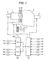
- FIG. 1 is a system structure view of a main portion of the control apparatus for the vehicle having the twin clutch type transmission applied in the first embodiment of the present invention.
- an engine 1 as a driving power source, a gear type transmission 2, a first clutch 3a, a second clutch 3b, a final gear 7, a differential gear 8, and a driving wheel 9 is shown.
- the first clutch 3a is used for gear trains of even gear trains (2nd gear position, 4th gear position, and 6th gear position) and a reverse gear position, in the gear type transmission 2 comprising forward six gear positions and one reverse gear position.
- the second clutch 3b is connected to odd gear trains (1st gear position, 3rd gear position, and 5th gear position).
- Driving torque from the engine 1 is given to the gear type transmission 2 via the first clutch 3a or second clutch 3b.
- the torque is transferred from the final gear 7 and differential gear 8 to the driving wheel 9 via a predetermined gear train and a shaft corresponding to a selected gear position.
- the gear type transmission is explained later in detail.
- a structure of the electronic system includes a transmission control apparatus 100, an engine control apparatus 200, and a navigation control apparatus 300.
- the three control apparatuses execute various information exchange through two-way data communications.
- the transmission control apparatus 100 is equipped with an accelerator position sensor 101, a speed sensor 102 for clutch-output shaft, a speed sensor for a transmission output (vehicle speed sensor) 103, a shift position sensor (gear position sensing means) 104, a brake switch 105, a shift lever switch 106, a mode switch 107, a clutch actuator 4, and a shift actuator 5.
- the accelerator position sensor 101 senses an amount of an operation of an accelerator by a driver, and outputs the sensed signal to the transmission control apparatus 100.
- the clutch output shaft-speed sensor 102 senses an output shaft speed of the first clutch 3a and an output shaft speed of the second clutch 3b, and outputs the sensed signals to the transmission control apparatus 100.
- the transmission output shaft-speed sensor 103 senses a speed of the output shaft of the gear type transmission 2, and outputs the sensed signal to the transmission control apparatus 100.
- the shift sensor 104 senses a shift position for forming a predetermined gear position by use of the shift actuator 5, and outputs the sensed signal to the transmission control apparatus 100.
- the brake switch 105 senses whether a driver operates a brake, and outputs the sensed signal to the transmission control apparatus 100.
- the shift lever switch 106 senses a position of a shift lever operated by the driver, e.g., in a case of switching between forward and reverse, and outputs the sensed signal to the transmission control apparatus 100.
- the shifting mode switch 107 senses an automatic shifting mode or a manual shifting mode selected by the driver, and outputs the sensed signal to the transmission control apparatus 100.
- the clutch actuator 4 performs engagement and disengagement of the first clutch 3a and the second clutch 3b respectively in accordance with a control instruction from the transmission control apparatus 100, so that power from the engine 1 is transferred and interrupted to the output shaft of the transmission. Further, the clutch actuator 4 switches torque between both clutches to achieve shifting while the vehicle is traveling.
- the shift actuator 5 is the above-described gear selection apparatus.
- the shift actuator 5 selectively operates a 1st- 3rd shift fork (not shown), a 5th shift fork (not shown), a 2nd-4th shift fork (not shown), and a 6th-reverse shift fork (not shown).
- the clutch-output shaft and the transmission-output shaft are connected to each other to form a predetermined gear position.
- a predetermined gear train connected to a non-driven side is operated prior to an execution of the next shifting to achieve the pre-shift.
- the engine control apparatus 200 is equipped with an accelerator position sensor 201, a throttle opening sensor 202, and an electronic throttle device 6.
- the accelerator position sensor 201 senses an amount of an operation of an accelerator by the driver, and outputs the sensed signal to the engine control apparatus 200.
- the throttle opening sensor 202 senses an opening of a throttle valve of the electronic throttle device 6, and outputs the sensed signal to the engine control apparatus 200.
- the electronic throttle 6 controls the opening of the throttle valve provided to an engine intake system in accordance with a control instruction from the engine control apparatus 200.
- the transmission control apparatus 100 sends a required-torque instruction to the engine control apparatus 200.
- the engine control apparatus 200 operates the electronic throttle device 6 or changes an ignition timiming in accordance with the received required-torque instruction. Accordingly, driving torque generated by the engine 1 can be controlled.
- the navigation control apparatus 300 is equipped with a direction sensor 301, a GPS sensor 302, and a vehicle speed sensor 303.
- the direction sensor 301 senses a direction of a vehicle, and outputs the sensed signal to a navigation control apparatus 300.
- the GPS sensor 302 senses a GPS signal from a GPS satellite (not shown), and outputs the sensed signal to the navigation control apparatus 300.
- the vehicle speed sensor 303 senses a rotation speed of a wheel, and outputs the sensed signal to the navigation control apparatus 300.
- the navigation control apparatus 300 calculates a current position where a vehicle is traveling, through a known method by use of the signals of the above sensors.
- Various map information stored in a storage section built in the navigation control apparatus 300 such as a radius of curvature and road gradient at the current position on a vehicle path, is read, and sent to the transmission control unit 100 by use of the two-way data communications.
- the transmission control unit 100 controls the shift actuator 5 prior to the next shifting, by use of the map information corresponding to a current position calculated in the navigation control apparatus 300, to execute the pre-shift.
- the main portion of the control apparatus for the vehicle including the twin clutch type transmission is structured as described above, so that an accuracy of prediction about shifting in the manual shifting mode can be improved, and a delay of shifting due to failure in the pre-shift gear selection can be kept down.
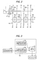
- FIG. 2 is a skeleton diagram showing the twin clutch type transmission of the first embodiment of the present invention.
- the engine 1 is directly connected to the clutches 3 with a twin clutch 3a, 3b.
- the first clutch 3a is connected to its output shaft 41a directly.
- the second clutch 3b is connected to its output shaft 41b directly.
- the second clutch-output shaft 41b is made of a hollow shaft.
- the first clutch-output shaft 41a is put through the hollow portion of the second clutch output shaft 41b, and can rotate without relation of the second clutch output shaft 41b.
- a 2nd drive gear 52, a 4th drive gear 54, and a 6th drive gear 56 are fixed on the first clutch-output shaft 41a to be an input shaft of the transmission, and these gears are capable of rotating together with the first clutch-output shaft 41a without relation of the second ctutch-output shaft 41b.
- a 1st drive gear 51, a 3rd drive gear 53, a 5th drive gear 55, and a reverse drive gear (not shown) are fixed to the second clutch output shaft 41b, and these clutches are capable of rotating without relation of the first output shaft 41a.
- a first clutch-speed sensor 102a is attached to the 2nd drive gear 52 to sense a speed of its output shaft.
- a second clutch speed sensor 102b is attached to the 1st drive gear 51 to sense a speed of its output shaft.
- a 1st driven gear 61, a 2nd driven gear 62, a 3rd driven gear 63, a 4th driven gear 64, a 5th driven gear 65, a 6th driven gear 66, and a reverse driven gear (not shown) are mounted freely on the transmission-output shaft 42.
- a first mesh clutch 70a having a rotation synchronization mechanism is provided between the 1st driven gear 61 and the 3rd driven gear 63.
- the shift actuator 5 (not shown) is controlled to operate the 1st-3rd shift fork for moving the first mesh clutch 70a in the left and right directions. Accordingly, the 1st driven gear 61 or 3rd driven gear 63 can be connected to the transmission-output shaft 42. Rotation torque transferred from the 1st drive gear 51 or 3rd drive gear 53 to the 1st driven gear 61 or 3rd driven gear 63 is transferred to the transmission-output shaft 42 via a first mesh clutch 70a.
- a second mesh clutch 70b for the 5th driven gear 65 is provided on the output shaft 42.
- the shift actuator 5 (not shown) is controlled to operate the 5th shift fork for moving the second mesh clutch 70b in the right direction. Accordingly, the 5th driven gear 65 can be connected to the output shaft 42.
- a third mesh clutch 70c is provided between the 2nd driven gear 62 and 4th driven gear 64.
- the shift actuator 5 (not shown) is controlled to operate the 2nd-4th shift fork for moving the third mesh clutch 70c in the left and right directions. Accordingly, the 2nd driven gear 62 or 4th driven gear 64 can be connected to the output shaft 42.
- a forth mesh clutch 70d is provided between the 6th driven gear 66 and reverse driven gear (not shown).
- the shift actuator 5 (not shown) is controlled to operate the 6th-reverse shift fork for moving the forth mesh clutch 70d in the left and right directions. Accordingly, the 6th driven gear 66 or reverse driven gear can be connected to the output shaft 42.
- the output shaft speed sensor 103 is provided to the 1st driven gear 61, and senses a speed of the transmission-output shaft 42.
- the shift actuator 5 selects the corresponding shift fork to operate one of the above mesh clutches. Thereby, the pre-shift is achieved.
- a shifting instruction is produced in the transmission control apparatus 100, it is determined whether the operation of the corresponding mesh clutch is complete. When the operation is complete, the clutch actuator 4 is operated to the engagement and disengagement for the first clutch 3a and second clutch 3b. Then, actual shifting is executed.
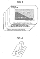
- FIG. 3 is a control block diagram showing a main portion of the transmission control apparatus 100 of the first embodiment of the present invention.
- the transmission control apparatus 100 comprises a pre-shift gear selection section 110 for an automatic shifting mode, a pre-shift gear selection section 120 for a manual shifting mode, and a selection switch section 130.
- the automatic shifting mode pre-shift gear selection section 110 selects a pre-shift gear position for the automatic shifting mode in accordance with an accelerator position APS sensed by the accelerator position sensor 101 and a vehicle speed VSP calculated from a signal sensed by the transmission output shaft speed sensor 103. Concretely, as shown in FIG. 4, by use of a data map having a horizontal axis for the vehicle speed VSP and a vertical axis for the accelerator position APS, it is determined whether a driving area is one where an up shift standby or a down shift standby is to be executed.
- the above data map can be set for each current gear position of the driving shaft separately.
- the above current gear position is determined in the transmission control apparatus 100 by use of a signal of the shift position sensor 104.
- the manual shifting mode pre-shift gear selection section 120 shown in FIG. 3 selects a pre-shift gear position in accordance with external information acquired in an external information acquisition section 400.
- the external information acquisition section 400 comprises the navigation control apparatus 300, but it is not limited to the navigation control apparatus 300.
- the external information acquisition section 400 may comprise, e.g., a radar apparatus for measuring a distance between one's own vehicle and the one ahead, and a camera apparatus for taking in an image of a surrounding of a vehicle, or a communications section for communicating with an external of the vehicle.
- the above external information may comprise a radius of curvature, a load gradient, a distance between one's own vehicle and the one ahead, or information about a freezing road.
- a driving area is in the up shift standby area or down shift standby area. Namely, regardless of an accelerator operation by a driver, when a radius of curvature is small, it is determined that the driving area is in the up shift standby area, and when a radius of curvature is large, it is determined that a driving area is in the down shift standby area.
- the above data map can be set for each current gear position of the driving shaft separately.
- the selection switch section 130 shown in FIG. 3 decides whether to adopt either computation method by the automatic transmission mode pre-shift gear selection section 110 or the manual transmission mode pre-shift gear selection section 120.
- the computation method of the pre-shift gear selection means is switched.
- the shift lever comprises a P range for parking a vehicle, an R range for reversing the vehicle, an N range in which the vehicle is not driven, and a D range for forwarding the vehicle.
- an M range can be selected.
- the shift lever is operated as described above to input a signal of the mode switch 106 (not shown) contained in the shift lever to the transmission control apparatus 100, so that the shifting mode is switched between the automatic shifting mode and manual shifting mode.
- the main portion of the transmission control apparatus 100 is structured as described above, so that an accuracy of prediction about shifting can be improved, and a delay of shifting due to failure of the pre-shift selection can be kept down.
- the radius of curvature Rc received from the navigation control apparatus 300 although is used as a condition for selecting gear to be used for the pre-shift in the above manual shifting mode, such information used for the pre-shift gear selection is not limited to it.
- the navigation control apparatus 300 calculates a distance from a present location to an approaching road curve, which has a radius of curvature equal to or under a predetermined value, and the distance may be used as the condition for selecting gear to be used for the pre-shift.
- a radius of curvature in a road under vehicle traveling may be obtained by a camera apparatus, and a value of the radius of curvature may be used for selecting gear to be used for the pre-shift.
- a camera apparatus a vehicle mounted camera for originally taking in an image concerning a scene ahead of the vehicle may be adopted.
- information from a vehicle mounted radar apparatus which originally is used for measuring a distance between one's own vehicle and the one ahead vehicle, may be adopt for the pre-shift.
- FIG. 7 is a flowchart showing main processes of the transmission control apparatus 100 of the first embodiment of the present invention.
- Step S71 a signal of the mode switch 106 is took in to determine whether the shifting mode selects the automatic shifting mode.
- the flow goes to Step S72.
- a process in Step 72 is executed.
- the determination is NO
- the flow goes to Step S73.
- a process in Step 73 is executed.
- Step S72 a pre-shift gear is selected for the automatic shifting mode as shown in FIG. 4.
- a pre-shift gear position is selected in accordance with an accelerator operation by a driver. Concrete processes of the automatic shifting mode pre-shift gear selection executed in Step S72 are explained in reference to FIG. 8.
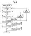
- FIG. 8 Concrete processes of the automatic shifting mode pre-shift gear selection executed in Step S72 are explained in reference to FIG. 8.
- Step S81 it is determined whether a current gear position of a currently traveling vehicle is in the 1st gear position.
- the current gear position is determined by use of a signal sensed in the shift position sensor 104.
- Step S82 in accordance with a data map for the 1st gear, it is determined whether a driving area is in the up shift area or down shift area.
- Step 83 it is determined whether the current gear position is in the 2nd gear position.
- Step S84 determines when the driving area is in the up shift area or down shift area in accordance with a data map for the 2nd gear position. The same processes as above are executed for 3rd to 6th gear positions.
- Step S87 it is determined whether to execute the up shift standby.
- Step S88 the flow goes to Step S89.
- Step S88 the pre-shift gear position is calculated by incrementing the current gear position.
- Step S89 it is determined whether to execute the down shift standby.
- Step S90 calculate the pre-shift gear position calculated by decrementing the current gear position. Then, the processes of the automatic shifting mode pre-shift gear selection are complete.
- FIG. 9 is a flowchart of the manual shifting mode pre-shift gear selection means.
- This process flow uses the same process form as the automatic shifting mode.
- a current gear position is determined, and it is determined whether the pre-shift gear position in the manual shifting is in a position for the up shift standby or down shift standby by use of a data map for each gear position.
- the concrete data maps in the manual shifting mode are structured as shown in FIG 5. For example, it is determined whether a driving area is in the up shift standby area or down shift standby area in accordance with a radius of curvature of a traveling rode.
- Steps S97 to S100 the current gear position is incremented in the case of the up shift standby, and the current gear position is decremented in the case of the down shift standby.
- the pre-shift gear position is calculated as described above, and the process flow for the manual shifting mode pre-shift gear selection ends.
- the main process of the transmission control apparatus 100 is structured as shown in FIGS. 7 to 9, so that the an accuracy of prediction of shifting in the manual shifting mode can be improved, and a delay of the shifting due to failure of the pre-shift gear selection can be kept down.
- FIG. 10 is a time chart explaining a main portion of a control of the transmission control apparatus 100 when a pre-shift gear is selected properly.
- FIG. 10 shows a current gear position and a pre-shift gear position;
- (B) shows a shift position sensed by the shift position sensor 104 attached to the above-described each shift fork;
- (C) shows a target torque instruction of the first clutch 3a and the second clutch 3b; and
- (D) shows an engine speed and the two clutch output shaft speeds.
- FIG. 10 shows that a 3rd-to-4th up-shift instruction is issued at a time to when a current gear position is in the 3rd gear position, and a pre-shift gear position is in the 4th gear position because of the determination of executing the up shift.
- so-cold clutch to clutch is executed, namely the clutches are switched at the same time as the issue of the shifting instruction, and the shifting is done promptly, because the pre-shift gear is selected properly.
- the target torque of the second clutch 3b having been used for the driving shaft until now is decreased, and the target torque of the first clutch 3a for having been used for the non-driving shaft until now is increased.
- the clutch to clutch operation is completed.
- the switch of the clutches is completed at a time t1
- the engine speed changes toward a speed of the first clutch output shaft because the engine speed is restrained by a speed of the first clutch 3a.
- the shifting operations are completed.
- the pre-shift gear position is updated from the 4th gear position to 5th gear position.
- the 5th shift position is rendered from a neutral position (SF_N) to a 5th engagement position (SF_H).
- SF_N neutral position
- SF_H 5th engagement position
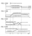
- FIG. 11 is a time chart explaining the main portion of a control of the transmission control apparatus 100 when the pre-shift gear is incorrectly selected.
- the content of (A) to (D) in FIG. 11 is the same as that in FIG. 10.
- FIG. 11 shows a case where a down shift instruction from the 3rd gear position to 2nd gear position is issued at the time t0 in spite of the fact that the pre-shift gear position is in the 4th gear position because of the determination of up shift.
- the 2nd-4th shift position is switched from a 4th engagement position (SF_L) to a 2nd engagement position (SF_H) because the pre-shift gear has been incorrectly selected.
- the clutches are operated to start actual shifting. First, target torque of the second clutch 3b having been used for the driving shaft until now is decreased, and the engine speed is increased. When it is determined that the engine speed has increased to a speed corresponding to the 2nd gear at the time T2, target torque of the second clutch 3b is decreased, and target torque of the first clutch 3a having been used for the non-driving shaft until now is increased. Then, the clutches are switched, so called clutch to clutch is executed. When it is determined that operation of clutch to clutch is completed at the time t3, the pre-shift gear position is updated from the 4th gear position to 3rd gear position.
- the 1st-3rd shift position has been already in the 3rd gear engagement position (SF_L), the 1st-3rd shift position does not change.
- the pre-shift gear is incorrectly selected, the actual shifting can not start during from the time t0 to t1. Therefore, the shifting response is delayed to make a driver feel uncomfortable.
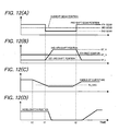
- FIG. 12 is a time chart explaining the main portion of a control of the transmission control apparatus 100 when a pre-shift gear is selected in the manual shifting mode.
- (A) shows a current gear position and a pre-shift gear position
- (B) shows a shift position sensed by the shift sensor 104 attached to each of the above shift forks
- (C) shows a radius of curvature of a traveling road (the radius of curvature is calculated in the navigation control apparatus 300)
- (D) shows an accelerator position, which is an amount of an operation of accelerator by a driver, the amount being sensed in the accelerator position sensor 101:
- FIG. 12 shows a time chart explaining the main portion of a control of the transmission control apparatus 100 when a pre-shift gear is selected in the manual shifting mode.
- (B) shows a shift position sensed by the shift sensor 104 attached to each of the above shift forks
- (C) shows a radius of curvature of a traveling road (the radius of curvature is calculated in the navigation control apparatus 300
- Rc_CHG is a border between the up shift standby area and the down shift standby area shown in FIG. 5, at the time t1. Then, the pre-shift gear position is updated from the 4th gear position to 2nd gear position.
- the 2nd-4th gear shift position is rendered from a 4th engagement position (SF_L) to 2nd engagement position (SF_H) to execute the down shift standby.
- the down shift standby is executed before the driver determines to enter the curved section and operates the accelerator to decelerate the vehicle.
- the pre-shift gear is updated from the 2nd gear position to 4th gear position.
- the 2nd-4th shift position is rendered from the 2nd engagement position (SF_H) to 4th engagement position (SF_L) to execute the up shift standby.
- the up shift standby is executed before the driver determines to pass the curved section and operates the accelerator to accelerate the vehicle again.
- the transmission control apparatus 100 is controlled as described above, so that an accuracy of prediction about the shifting in the manual shifting mode can be improved, and a delay of the shifting due to failure of the pre-shift selection can be kept down.
- FIG. 13 is a system structure diagram showing a main portion of the vehicular control apparatus for the vehicle having the twin clutch type transmission of the second embodiment of the present invention.
- the system structure diagram of FIG. 13 has the same main structure as the first embodiment shown in FIG. 1.
- FIG. 13 shows an engine 1, which is a driving source of a vehicle, a gear type transmission 2, a first clutch 3a, a second clutch 3b, a final gear 7, a differential 8, a driving wheel 9, and a brake actuator 10.
- the first clutch 3a is used for gear trains of even gears (2nd gear, 4th gear, and 6th gear) and a reverse gear position.
- total gear trains of the gear type transmission 2 is comprised of six forward gear positions and one reverse gear position.
- the second clutch 3b is used for odd gears (1st gear, 3rd gear, and 5th gear).
- Driving torque produced in the engine 1 is inputted to the gear type transmission 2 via the first clutch 3a or second clutch 3b, and transferred via a predetermined gear train, a shaft corresponding to each gear position, the final gear 7 and differential 8 to the driving wheel 9.
- the brake actuator 10 is controlled, so that a braking force of the vehicle can be changed without an operation of a brake by a driver.
- the electronic control system includes a transmission 100, an engine control apparatus 200, and a distance between vehicles-control apparatus 500.
- various data can be communicated to each other by use of two-way data communications.
- the distance between vehicles-control system includes a radar apparatus 501, a speed sensor 502, and a switch 503 for distance between vehicles control.
- the radar apparatus 501 senses the distance between one's vehicle and the one ahead, and outputs the sensed signal to the control apparatus 500.
- the speed sensor senses a speed of the wheel, and outputs the sensed signal to the control apparatus 500.
- the switch 503 senses a driver's intention of executing a control for the distance between vehicles, and outputs the detected signal to the control apparatus 500.
- the control apparatus 500 controls the vehicle so that the distance between vehicles sensed in the radar apparatus 501 follows a previously set distance.
- the engine control apparatus 200 operates the electronic throttle apparatus 6 or changes an ignition time in accordance with the received required torque instruction. Then, driving torque produces by the engine 1 is increased or decreased.
- the engine control apparatus 200 receives a shifting instruction, the engine control apparatus 200 operates the clutch actuator 4 and the shift actuator 5 in accordance with the received shifting instruction to achieve the shifting.
- the control apparatus 500 for the distance between vehicles automatically controls a driving force and a braking force of the vehicle.
- a control response to the deceleration is more important. Therefore, in the transmission control apparatus 100, when being determined that the control for the distance between vehicles is being executed, the pre-shift gear position is in a position for the down shift standby.
- the transmission control apparatus 100 is controlled as described above, so that the control response to the deceleration during the distance between vehicles can be improved, and the vehicle can be controlled to be more safe.
- FIG. 14 is a flow chart showing main processes of the transmission control apparatus 100 of the second embodiment of the present invention.
- Step S41 a signal of the switch 503 for the distance between vehicles is received from the control apparatus 500 by use of the two-way communications to determine whether the control for the distance between vehicles is being controlled.
- Step S42 the flow goes to Step S42, and the normal pre-shift gear selection control shown in FIG. 7 is done.
- Step S43 the flow goes to Step S43, and the down shift standby is always executed regardless of a driving condition of the vehicle, such as an amount of an operation by a driver and a vehicle speed.
- Step S45 it is determined whether to execute the up shift standby.
- the flow goes to Step S46.
- Step S47 the pre-shift gear position is calculated by incrementing the current gear position.
- Step s47 it is determined whether to execute the down shift standby.
- the flow goes to Step S48, and the pre-shift gear position is calculated by decrementing the current gear position. Then, the process flow for the pre-shift gear selection is complete.
- the main processes of the transmission control apparatus 100 is structured as described above, so that the control response to the deceleration during control of the distance between vehicles can be improved, and the vehicle can be controlled to be more safe.
Landscapes
- Engineering & Computer Science (AREA)
- General Engineering & Computer Science (AREA)
- Mechanical Engineering (AREA)
- Control Of Transmission Device (AREA)
Applications Claiming Priority (1)
| Application Number | Priority Date | Filing Date | Title |
|---|---|---|---|
| JP2006053044A JP2007232047A (ja) | 2006-02-28 | 2006-02-28 | 自動車の制御装置および制御方法 |
Publications (2)
| Publication Number | Publication Date |
|---|---|
| EP1826464A2 true EP1826464A2 (de) | 2007-08-29 |
| EP1826464A3 EP1826464A3 (de) | 2011-01-05 |
Family
ID=38066764
Family Applications (1)
| Application Number | Title | Priority Date | Filing Date |
|---|---|---|---|
| EP07001775A Withdrawn EP1826464A3 (de) | 2006-02-28 | 2007-01-26 | Steuervorrichtung und Steuerverfahren für ein Fahrzeug mit Doppelkupplung-Automatikgetriebe |
Country Status (4)
| Country | Link |
|---|---|
| US (1) | US7591203B2 (de) |
| EP (1) | EP1826464A3 (de) |
| JP (1) | JP2007232047A (de) |
| CN (1) | CN101029686B (de) |
Cited By (3)
| Publication number | Priority date | Publication date | Assignee | Title |
|---|---|---|---|---|
| WO2010004187A1 (fr) * | 2008-07-10 | 2010-01-14 | Renault S.A.S. | Procede et dispositif de commande de transmission d'un groupe motopropulseur de vehicule automobile |
| EP2151609A1 (de) * | 2008-08-04 | 2010-02-10 | AISIN AI Co., Ltd. | Doppelkupplungsgetriebe |
| EP3604863A4 (de) * | 2017-03-23 | 2020-12-30 | Hitachi Automotive Systems, Ltd. | Sendesteuerungsvorrichtung |
Families Citing this family (36)
| Publication number | Priority date | Publication date | Assignee | Title |
|---|---|---|---|---|
| US8392047B2 (en) * | 2007-06-04 | 2013-03-05 | Zf Friedrichshafen Ag | System for preventing damage to a vehicle |
| JP2009041601A (ja) | 2007-08-07 | 2009-02-26 | Hitachi Ltd | 自動変速機の制御装置および制御方法 |
| JP4812731B2 (ja) * | 2007-10-30 | 2011-11-09 | 本田技研工業株式会社 | 車両のクラッチ制御装置 |
| JP5162767B2 (ja) * | 2008-03-28 | 2013-03-13 | 本田技研工業株式会社 | クラッチ制御装置 |
| JP4921509B2 (ja) | 2009-03-31 | 2012-04-25 | アイシン・エィ・ダブリュ株式会社 | 自動変速機の制御装置 |
| JP4999874B2 (ja) * | 2009-03-31 | 2012-08-15 | アイシン・エィ・ダブリュ株式会社 | 自動変速機の制御装置 |
| US8475336B2 (en) * | 2009-07-30 | 2013-07-02 | GM Global Technology Operations LLC | Hydraulic control system for a dual clutch transmission |
| US8843284B2 (en) * | 2009-08-14 | 2014-09-23 | Toyota Motor Engineering & Manufacturing North America, Inc. | Systems and methods for controlling manual transmissions |
| US8225687B2 (en) * | 2009-09-09 | 2012-07-24 | GM Global Technology Operations LLC | Hydraulic control systems for dual clutch transmissions |
| US8429994B2 (en) | 2009-09-09 | 2013-04-30 | GM Global Technology Operations LLC | Hydraulic control systems for dual clutch transmissions |
| US8403792B2 (en) * | 2009-10-21 | 2013-03-26 | GM Global Technology Operations LLC | Hydraulic control systems for dual clutch transmissions |
| JP5445758B2 (ja) * | 2009-11-26 | 2014-03-19 | ダイムラー・アクチェンゲゼルシャフト | 車両用変速機制御装置 |
| JP5653608B2 (ja) * | 2009-11-26 | 2015-01-14 | ダイムラー・アクチェンゲゼルシャフトDaimler AG | 車両用変速機制御装置 |
| US8192176B2 (en) * | 2009-12-10 | 2012-06-05 | GM Global Technology Operations LLC | Hydraulic fluid supply system having active regulator |
| US8443687B2 (en) * | 2009-12-14 | 2013-05-21 | GM Global Technology Operations LLC | Electro-hydraulic control system for a dual clutch transmission |
| US8887498B2 (en) | 2009-12-18 | 2014-11-18 | Gm Global Technology Operations, Llc | Transmission hydraulic control system having an accumulator bypass valve assembly |
| US8402855B2 (en) * | 2010-01-11 | 2013-03-26 | GM Global Technology Operations LLC | Hydraulic control systems for dual clutch transmissions |
| US8567580B2 (en) * | 2010-01-22 | 2013-10-29 | GM Global Technology Operations LLC | Electro-hydraulic control system for a dual clutch transmission |
| US8413777B2 (en) * | 2010-02-17 | 2013-04-09 | GM Global Technology Operations LLC | High efficiency hydraulic transmission control system |
| US8234946B2 (en) * | 2010-02-17 | 2012-08-07 | GM Global Technology Operations LLC | Hydraulic control system for a dual clutch transmission |
| DE112011104290A5 (de) * | 2010-08-12 | 2013-11-07 | Schaeffler Technologies AG & Co. KG | Verfahren zum Betreiben eines automatisierten Doppelkupplungsgetriebes |
| US8839928B2 (en) | 2010-12-02 | 2014-09-23 | Gm Global Technology Operations, Llc | Electro-hydraulic control system for a dual clutch transmission |
| US8733521B2 (en) | 2010-12-06 | 2014-05-27 | Gm Global Technology Operations | Apparatus for and method of controlling a dual clutch transmission |
| US8904893B2 (en) | 2010-12-06 | 2014-12-09 | Gm Global Technology Operations, Llc | Method of controlling a dual clutch transmission |
| US8740748B2 (en) | 2010-12-08 | 2014-06-03 | Gm Global Technology Operations, Llc | Control system and method for a dual clutch transmission |
| US8738257B2 (en) | 2010-12-08 | 2014-05-27 | Gm Global Technology Operations, Llc | Electro-hydraulic control system and method for a dual clutch transmission |
| US8702564B2 (en) | 2010-12-09 | 2014-04-22 | GM Global Technology Operations LLC | Electro-hydraulic control system and method for a dual clutch transmission |
| JP5896647B2 (ja) * | 2011-08-30 | 2016-03-30 | アイシン・エーアイ株式会社 | デュアルクラッチ式自動変速機 |
| JP5836048B2 (ja) * | 2011-10-11 | 2015-12-24 | アイシン・エーアイ株式会社 | 変速機 |
| JP5824437B2 (ja) * | 2012-09-28 | 2015-11-25 | 本田技研工業株式会社 | ツインクラッチ制御装置 |
| JP2016205538A (ja) * | 2015-04-24 | 2016-12-08 | トヨタ自動車株式会社 | 車両の制御装置 |
| CN106931153B (zh) * | 2015-12-31 | 2018-07-17 | 上海汽车集团股份有限公司 | 变速箱控制单元及其拨叉预挂档方法 |
| CN106949234B (zh) * | 2017-04-27 | 2018-10-09 | 上海汽车变速器有限公司 | 双离合变速器功能安全监控方法 |
| CN109488760B (zh) * | 2017-09-11 | 2020-09-04 | 长城汽车股份有限公司 | 双离合变速系统的控制策略 |
| KR102081334B1 (ko) * | 2018-11-27 | 2020-02-25 | 현대 파워텍 주식회사 | 자동 변속기 차량의 엔진 제어 장치 및 방법 |
| CN111350811A (zh) * | 2018-12-24 | 2020-06-30 | 长城汽车股份有限公司 | 车辆及其变速器的选档方法与装置 |
Citations (2)
| Publication number | Priority date | Publication date | Assignee | Title |
|---|---|---|---|---|
| JPH06221347A (ja) | 1992-10-23 | 1994-08-09 | Borg Warner Automot Inc | 副軸自動変速機 |
| JPH09318361A (ja) | 1996-05-30 | 1997-12-12 | Minolta Co Ltd | 弾性表面波ジャイロスコープ |
Family Cites Families (24)
| Publication number | Priority date | Publication date | Assignee | Title |
|---|---|---|---|---|
| JPH06272753A (ja) * | 1993-03-19 | 1994-09-27 | Oki Electric Ind Co Ltd | 電子制御変速装置 |
| JPH08334168A (ja) * | 1995-06-06 | 1996-12-17 | Aqueous Res:Kk | 多段変速装置 |
| JP3632273B2 (ja) * | 1996-01-25 | 2005-03-23 | 日産自動車株式会社 | 車両用駆動力制御装置 |
| JP2903380B2 (ja) * | 1996-02-23 | 1999-06-07 | 株式会社エクォス・リサーチ | 車両制御装置 |
| DE19631983C1 (de) * | 1996-08-08 | 1998-02-12 | Volkswagen Ag | Verfahren zum Schalten eines Doppelkupplungsgetriebes und Doppelkupplungsgetriebe mit Synchronisiereinrichtung |
| JPH10318361A (ja) * | 1997-05-21 | 1998-12-04 | Toyota Motor Corp | ツインクラッチ式自動変速機の変速制御装置 |
| JP2000046169A (ja) * | 1998-07-29 | 2000-02-18 | Toyota Motor Corp | 車両用制御装置 |
| JP3955158B2 (ja) * | 1998-08-24 | 2007-08-08 | 本田技研工業株式会社 | 自動変速機の制御装置 |
| JP2000074198A (ja) * | 1998-09-01 | 2000-03-07 | Aisin Aw Co Ltd | 車両制御装置、車両制御方法及びそのプログラムを記録した記録媒体 |
| JP2001173740A (ja) * | 1999-12-16 | 2001-06-26 | Aisin Aw Co Ltd | 自動変速機制御装置、自動変速機制御方法及びそのプログラムを記録した記録媒体 |
| JP4459361B2 (ja) * | 2000-02-09 | 2010-04-28 | 本田技研工業株式会社 | 自動変速機の制御装置 |
| JP2002096658A (ja) * | 2000-07-17 | 2002-04-02 | Hitachi Ltd | 自動車の制御方法、および制御装置 |
| DE10116545B4 (de) * | 2001-04-03 | 2005-04-21 | Siemens Ag | Verfahren zum Steuern eines automatischen Getriebes und für ein solches Verfahren geeignete Steuerung |
| DE10163401A1 (de) * | 2001-12-21 | 2003-07-03 | Zf Sachs Ag | Kraftfahrzeug mit einem Mehrfachkupplungs-Mehrganggetriebe |
| JP3738740B2 (ja) * | 2002-03-19 | 2006-01-25 | 日産自動車株式会社 | ツインクラッチ式歯車変速機 |
| JP3918596B2 (ja) * | 2002-03-20 | 2007-05-23 | 三菱自動車工業株式会社 | 変速機制御機構 |
| JP4125067B2 (ja) * | 2002-06-12 | 2008-07-23 | トヨタ自動車株式会社 | 車両用自動変速機の変速制御装置 |
| JP4378914B2 (ja) * | 2002-06-21 | 2009-12-09 | トヨタ自動車株式会社 | 複数クラッチ式変速機のシフト制御装置 |
| CN1415876A (zh) * | 2002-12-06 | 2003-05-07 | 吉林大学 | 双离合器式自动变速机构 |
| JP3952977B2 (ja) * | 2003-03-19 | 2007-08-01 | 日産自動車株式会社 | 多段式自動変速機の変速制御装置 |
| JP2005265176A (ja) * | 2004-02-17 | 2005-09-29 | Toyota Motor Corp | 車両の走行制御装置 |
| JP2006029476A (ja) * | 2004-07-16 | 2006-02-02 | Nissan Motor Co Ltd | 駆動力伝達装置 |
| JP4872235B2 (ja) * | 2005-04-28 | 2012-02-08 | 日産自動車株式会社 | 多段式自動変速機の変速制御装置 |
| JP4828929B2 (ja) * | 2005-12-19 | 2011-11-30 | 日立オートモティブシステムズ株式会社 | 自動変速機の制御装置,制御方法及び自動変速装置 |
-
2006
- 2006-02-28 JP JP2006053044A patent/JP2007232047A/ja not_active Withdrawn
-
2007
- 2007-01-18 CN CN200710002042.9A patent/CN101029686B/zh not_active Expired - Fee Related
- 2007-01-25 US US11/657,644 patent/US7591203B2/en not_active Expired - Fee Related
- 2007-01-26 EP EP07001775A patent/EP1826464A3/de not_active Withdrawn
Patent Citations (2)
| Publication number | Priority date | Publication date | Assignee | Title |
|---|---|---|---|---|
| JPH06221347A (ja) | 1992-10-23 | 1994-08-09 | Borg Warner Automot Inc | 副軸自動変速機 |
| JPH09318361A (ja) | 1996-05-30 | 1997-12-12 | Minolta Co Ltd | 弾性表面波ジャイロスコープ |
Cited By (6)
| Publication number | Priority date | Publication date | Assignee | Title |
|---|---|---|---|---|
| WO2010004187A1 (fr) * | 2008-07-10 | 2010-01-14 | Renault S.A.S. | Procede et dispositif de commande de transmission d'un groupe motopropulseur de vehicule automobile |
| FR2933759A1 (fr) * | 2008-07-10 | 2010-01-15 | Renault Sas | Procede et dispositif de commande de transmission d'un groupe motopropulseur de vehicule automobile |
| EP2151609A1 (de) * | 2008-08-04 | 2010-02-10 | AISIN AI Co., Ltd. | Doppelkupplungsgetriebe |
| US8387479B2 (en) | 2008-08-04 | 2013-03-05 | Aisin Ai Co., Ltd. | Dual clutch transmission control device |
| EP3604863A4 (de) * | 2017-03-23 | 2020-12-30 | Hitachi Automotive Systems, Ltd. | Sendesteuerungsvorrichtung |
| US11009122B2 (en) | 2017-03-23 | 2021-05-18 | Hitachi Automotive Systems, Ltd. | Transmission control device |
Also Published As
| Publication number | Publication date |
|---|---|
| JP2007232047A (ja) | 2007-09-13 |
| US7591203B2 (en) | 2009-09-22 |
| EP1826464A3 (de) | 2011-01-05 |
| US20070199395A1 (en) | 2007-08-30 |
| CN101029686A (zh) | 2007-09-05 |
| CN101029686B (zh) | 2010-09-08 |
Similar Documents
| Publication | Publication Date | Title |
|---|---|---|
| US7591203B2 (en) | Control apparatus and control method for vehicle | |
| JP6982564B2 (ja) | 車両制御装置 | |
| US8387479B2 (en) | Dual clutch transmission control device | |
| JP2019123328A (ja) | 車両及び制御装置 | |
| JP2019123327A (ja) | 車両用制御装置及び車載装置 | |
| JP2009281439A (ja) | 変速機構の制御装置、制御方法及び原動機付き車両の制御方法 | |
| CN108223789A (zh) | 用于对自动化的分组变速器进行换挡控制的方法 | |
| JP4792883B2 (ja) | 複数クラッチ式変速機の制御装置 | |
| CN104806747B (zh) | 离合器压力控制装置 | |
| JP2005172164A (ja) | 車両の制御装置 | |
| JP4396468B2 (ja) | 移動車両の変速制御装置 | |
| JP2014094596A (ja) | ハイブリッド車両の変速制御装置 | |
| JP4197820B2 (ja) | 副変速機を備えた変速機の変速制御装置 | |
| JP4389047B2 (ja) | 移動車両 | |
| JP2014054952A (ja) | ハイブリッド車両の制御装置 | |
| JP4881642B2 (ja) | 車両の変速制御装置 | |
| JPH08334168A (ja) | 多段変速装置 | |
| JP2021063578A (ja) | 自動変速機の制御装置及び、制御方法 | |
| JP4947091B2 (ja) | 移動車両 | |
| JP2021055680A (ja) | 自動変速機の制御装置及び、制御方法 | |
| JPH0519235Y2 (de) | ||
| JPH0512250U (ja) | 車両の自動変速装置 | |
| JPH0636356Y2 (ja) | 車両用自動変速装置 | |
| JPH0454363Y2 (de) | ||
| JPH0440982Y2 (de) |
Legal Events
| Date | Code | Title | Description |
|---|---|---|---|
| PUAI | Public reference made under article 153(3) epc to a published international application that has entered the european phase |
Free format text: ORIGINAL CODE: 0009012 |
|
| AK | Designated contracting states |
Kind code of ref document: A2 Designated state(s): AT BE BG CH CY CZ DE DK EE ES FI FR GB GR HU IE IS IT LI LT LU LV MC NL PL PT RO SE SI SK TR |
|
| AX | Request for extension of the european patent |
Extension state: AL BA HR MK YU |
|
| 17P | Request for examination filed |
Effective date: 20090623 |
|
| PUAL | Search report despatched |
Free format text: ORIGINAL CODE: 0009013 |
|
| AK | Designated contracting states |
Kind code of ref document: A3 Designated state(s): AT BE BG CH CY CZ DE DK EE ES FI FR GB GR HU IE IS IT LI LT LU LV MC NL PL PT RO SE SI SK TR |
|
| AX | Request for extension of the european patent |
Extension state: AL BA HR MK RS |
|
| RIC1 | Information provided on ipc code assigned before grant |
Ipc: F16H 61/02 20060101ALI20101130BHEP Ipc: F16H 61/688 20060101AFI20070612BHEP |
|
| STAA | Information on the status of an ep patent application or granted ep patent |
Free format text: STATUS: THE APPLICATION HAS BEEN WITHDRAWN |
|
| 18W | Application withdrawn |
Effective date: 20110615 |