EP1826497A2 - Procédé de préparation d'un flux d'air introduit dans l'espace d'un bâtiment par une installation de ventilation - Google Patents
Procédé de préparation d'un flux d'air introduit dans l'espace d'un bâtiment par une installation de ventilation Download PDFInfo
- Publication number
- EP1826497A2 EP1826497A2 EP07102453A EP07102453A EP1826497A2 EP 1826497 A2 EP1826497 A2 EP 1826497A2 EP 07102453 A EP07102453 A EP 07102453A EP 07102453 A EP07102453 A EP 07102453A EP 1826497 A2 EP1826497 A2 EP 1826497A2
- Authority
- EP
- European Patent Office
- Prior art keywords
- air
- ventilation system
- compact unit
- room
- ozone
- Prior art date
- Legal status (The legal status is an assumption and is not a legal conclusion. Google has not performed a legal analysis and makes no representation as to the accuracy of the status listed.)
- Withdrawn
Links
Images

Classifications
-
- A—HUMAN NECESSITIES
- A61—MEDICAL OR VETERINARY SCIENCE; HYGIENE
- A61L—METHODS OR APPARATUS FOR STERILISING MATERIALS OR OBJECTS IN GENERAL; DISINFECTION, STERILISATION OR DEODORISATION OF AIR; CHEMICAL ASPECTS OF BANDAGES, DRESSINGS, ABSORBENT PADS OR SURGICAL ARTICLES; MATERIALS FOR BANDAGES, DRESSINGS, ABSORBENT PADS OR SURGICAL ARTICLES
- A61L9/00—Disinfection, sterilisation or deodorisation of air
- A61L9/015—Disinfection, sterilisation or deodorisation of air using gaseous or vaporous substances, e.g. ozone
-
- A—HUMAN NECESSITIES
- A61—MEDICAL OR VETERINARY SCIENCE; HYGIENE
- A61L—METHODS OR APPARATUS FOR STERILISING MATERIALS OR OBJECTS IN GENERAL; DISINFECTION, STERILISATION OR DEODORISATION OF AIR; CHEMICAL ASPECTS OF BANDAGES, DRESSINGS, ABSORBENT PADS OR SURGICAL ARTICLES; MATERIALS FOR BANDAGES, DRESSINGS, ABSORBENT PADS OR SURGICAL ARTICLES
- A61L9/00—Disinfection, sterilisation or deodorisation of air
- A61L9/16—Disinfection, sterilisation or deodorisation of air using physical phenomena
- A61L9/22—Ionisation
-
- B—PERFORMING OPERATIONS; TRANSPORTING
- B03—SEPARATION OF SOLID MATERIALS USING LIQUIDS OR USING PNEUMATIC TABLES OR JIGS; MAGNETIC OR ELECTROSTATIC SEPARATION OF SOLID MATERIALS FROM SOLID MATERIALS OR FLUIDS; SEPARATION BY HIGH-VOLTAGE ELECTRIC FIELDS
- B03C—MAGNETIC OR ELECTROSTATIC SEPARATION OF SOLID MATERIALS FROM SOLID MATERIALS OR FLUIDS; SEPARATION BY HIGH-VOLTAGE ELECTRIC FIELDS
- B03C3/00—Separating dispersed particles from gases or vapour, e.g. air, by electrostatic effect
- B03C3/017—Combinations of electrostatic separation with other processes, not otherwise provided for
-
- B—PERFORMING OPERATIONS; TRANSPORTING
- B03—SEPARATION OF SOLID MATERIALS USING LIQUIDS OR USING PNEUMATIC TABLES OR JIGS; MAGNETIC OR ELECTROSTATIC SEPARATION OF SOLID MATERIALS FROM SOLID MATERIALS OR FLUIDS; SEPARATION BY HIGH-VOLTAGE ELECTRIC FIELDS
- B03C—MAGNETIC OR ELECTROSTATIC SEPARATION OF SOLID MATERIALS FROM SOLID MATERIALS OR FLUIDS; SEPARATION BY HIGH-VOLTAGE ELECTRIC FIELDS
- B03C3/00—Separating dispersed particles from gases or vapour, e.g. air, by electrostatic effect
- B03C3/02—Plant or installations having external electricity supply
- B03C3/04—Plant or installations having external electricity supply dry type
- B03C3/14—Plant or installations having external electricity supply dry type characterised by the additional use of mechanical effects, e.g. gravity
- B03C3/155—Filtration
-
- B—PERFORMING OPERATIONS; TRANSPORTING
- B03—SEPARATION OF SOLID MATERIALS USING LIQUIDS OR USING PNEUMATIC TABLES OR JIGS; MAGNETIC OR ELECTROSTATIC SEPARATION OF SOLID MATERIALS FROM SOLID MATERIALS OR FLUIDS; SEPARATION BY HIGH-VOLTAGE ELECTRIC FIELDS
- B03C—MAGNETIC OR ELECTROSTATIC SEPARATION OF SOLID MATERIALS FROM SOLID MATERIALS OR FLUIDS; SEPARATION BY HIGH-VOLTAGE ELECTRIC FIELDS
- B03C3/00—Separating dispersed particles from gases or vapour, e.g. air, by electrostatic effect
- B03C3/34—Constructional details or accessories or operation thereof
- B03C3/38—Particle charging or ionising stations, e.g. using electric discharge, radioactive radiation or flames
- B03C3/383—Particle charging or ionising stations, e.g. using electric discharge, radioactive radiation or flames using radiation
-
- F—MECHANICAL ENGINEERING; LIGHTING; HEATING; WEAPONS; BLASTING
- F24—HEATING; RANGES; VENTILATING
- F24F—AIR-CONDITIONING; AIR-HUMIDIFICATION; VENTILATION; USE OF AIR CURRENTS FOR SCREENING
- F24F8/00—Treatment, e.g. purification, of air supplied to human living or working spaces otherwise than by heating, cooling, humidifying or drying
- F24F8/10—Treatment, e.g. purification, of air supplied to human living or working spaces otherwise than by heating, cooling, humidifying or drying by separation, e.g. by filtering
- F24F8/192—Treatment, e.g. purification, of air supplied to human living or working spaces otherwise than by heating, cooling, humidifying or drying by separation, e.g. by filtering by electrical means, e.g. by applying electrostatic fields or high voltages
-
- F—MECHANICAL ENGINEERING; LIGHTING; HEATING; WEAPONS; BLASTING
- F24—HEATING; RANGES; VENTILATING
- F24F—AIR-CONDITIONING; AIR-HUMIDIFICATION; VENTILATION; USE OF AIR CURRENTS FOR SCREENING
- F24F8/00—Treatment, e.g. purification, of air supplied to human living or working spaces otherwise than by heating, cooling, humidifying or drying
- F24F8/10—Treatment, e.g. purification, of air supplied to human living or working spaces otherwise than by heating, cooling, humidifying or drying by separation, e.g. by filtering
- F24F8/192—Treatment, e.g. purification, of air supplied to human living or working spaces otherwise than by heating, cooling, humidifying or drying by separation, e.g. by filtering by electrical means, e.g. by applying electrostatic fields or high voltages
- F24F8/194—Treatment, e.g. purification, of air supplied to human living or working spaces otherwise than by heating, cooling, humidifying or drying by separation, e.g. by filtering by electrical means, e.g. by applying electrostatic fields or high voltages by filtering using high voltage
-
- F—MECHANICAL ENGINEERING; LIGHTING; HEATING; WEAPONS; BLASTING
- F24—HEATING; RANGES; VENTILATING
- F24F—AIR-CONDITIONING; AIR-HUMIDIFICATION; VENTILATION; USE OF AIR CURRENTS FOR SCREENING
- F24F8/00—Treatment, e.g. purification, of air supplied to human living or working spaces otherwise than by heating, cooling, humidifying or drying
- F24F8/20—Treatment, e.g. purification, of air supplied to human living or working spaces otherwise than by heating, cooling, humidifying or drying by sterilisation
- F24F8/24—Treatment, e.g. purification, of air supplied to human living or working spaces otherwise than by heating, cooling, humidifying or drying by sterilisation using sterilising media
- F24F8/26—Treatment, e.g. purification, of air supplied to human living or working spaces otherwise than by heating, cooling, humidifying or drying by sterilisation using sterilising media using ozone
-
- F—MECHANICAL ENGINEERING; LIGHTING; HEATING; WEAPONS; BLASTING
- F24—HEATING; RANGES; VENTILATING
- F24F—AIR-CONDITIONING; AIR-HUMIDIFICATION; VENTILATION; USE OF AIR CURRENTS FOR SCREENING
- F24F8/00—Treatment, e.g. purification, of air supplied to human living or working spaces otherwise than by heating, cooling, humidifying or drying
- F24F8/30—Treatment, e.g. purification, of air supplied to human living or working spaces otherwise than by heating, cooling, humidifying or drying by ionisation
-
- F—MECHANICAL ENGINEERING; LIGHTING; HEATING; WEAPONS; BLASTING
- F24—HEATING; RANGES; VENTILATING
- F24F—AIR-CONDITIONING; AIR-HUMIDIFICATION; VENTILATION; USE OF AIR CURRENTS FOR SCREENING
- F24F8/00—Treatment, e.g. purification, of air supplied to human living or working spaces otherwise than by heating, cooling, humidifying or drying
- F24F8/40—Treatment, e.g. purification, of air supplied to human living or working spaces otherwise than by heating, cooling, humidifying or drying by ozonisation
-
- Y—GENERAL TAGGING OF NEW TECHNOLOGICAL DEVELOPMENTS; GENERAL TAGGING OF CROSS-SECTIONAL TECHNOLOGIES SPANNING OVER SEVERAL SECTIONS OF THE IPC; TECHNICAL SUBJECTS COVERED BY FORMER USPC CROSS-REFERENCE ART COLLECTIONS [XRACs] AND DIGESTS
- Y02—TECHNOLOGIES OR APPLICATIONS FOR MITIGATION OR ADAPTATION AGAINST CLIMATE CHANGE
- Y02A—TECHNOLOGIES FOR ADAPTATION TO CLIMATE CHANGE
- Y02A50/00—TECHNOLOGIES FOR ADAPTATION TO CLIMATE CHANGE in human health protection, e.g. against extreme weather
- Y02A50/20—Air quality improvement or preservation, e.g. vehicle emission control or emission reduction by using catalytic converters
Definitions
- the invention relates to a method for processing an air flow introduced into the room of a building from a ventilation and air conditioning system, wherein the air flow is subjected to oxygen activation before it is discharged into the room of the building. Furthermore, the invention relates to a device for processing of the introduced from the ventilation system in the room airflow.
- Methods for processing an air stream to be introduced into a room are known in the art, including, for example, the DE 10 2004 003 269 A1 and on the DE 20 2004 012 352 U1 is pointed out.
- an oxygen activation is carried out in such a way that the air to be supplied is enriched with ions and / or with ozone.
- the quality of the breathing air is improved in terms of well-being and health. Furthermore, this can be counteracted by an early exhaustion of people working in the room and other deficiencies (eg allergies).
- the invention is therefore an object of the invention to provide a method for processing a introduced from a ventilation system in the space of a building air flow of the type mentioned above and an associated device that makes it possible to remedy the disadvantages mentioned or Reduce.
- the air treatment in space-saving manner and installation technology is easy to be possible.
- a particular aspect is furthermore that the use of the method and the device should also be possible if there are poor conditions with regard to the infrastructure of the energy supply.
- the solution of this problem by the invention according to the method is characterized in that the air flow from the air conditioning system is first introduced into an oxygen activation device designed as a compact unit in which an ion generation and / or ozone generation takes place, and that the thus treated air flow then discharged from the compact unit into the room of the building.
- the oxygen activation in the compact unit in a self-sufficient manner and largely, preferably completely, without external power supply is performed. This makes it possible to use the process in a location that does not have the infrastructure requirements for classic barrel processing plants.
- the ion generation takes place at a rate of at least 2 million ions / sec, preferably of 4 million ions / sec.
- the device according to the invention for processing an air flow introduced into the room of a building from a ventilation and air-conditioning system, the device having means for oxygen activation, is characterized in that the device is designed as a compact unit in which the means for activating oxygen are arranged the means for ion generation and / or ozone generation are formed.
- the device has a storage means for electrical energy, in which case in particular an accumulator, especially to a 12-volt accumulator, is thought.
- the compact unit is preferably arranged in a substantially cuboidal housing, which can be fixed to the ceiling of a room.
- the ion generating and / or ozone generating means may comprise an ion generator which is in communication with a high voltage generator. Accordingly, these means may comprise an ozone generator which is also in communication with a high voltage generator.
- the device may have signaling means which indicate the state of charge of the storage means for electrical energy, that is to say of the accumulator.
- a signal means can be designed as an optical display and a signal means as an acoustic display. Signaling means for indicating the operating state and / or the operating mode of the device can also be provided.
- the device comprises an air flow monitoring device.
- the air flow overflow device detects whether or sufficient air flow is present in the air duct or measures the flow velocity of the air in the air duct.
- an airspeed sensor can be provided.
- the airflow monitoring device may optionally be provided within the compact unit of the oxygen activation device, upstream or downstream of the oxygen activation device. In a first embodiment it is provided that the oxygen activation only starts from a predetermined air flow.
- the air flow monitoring device is in operative connection with a controller, preferably in the form of electronics, in order to connect or disconnect the oxygen activation.
- the amount of ions produced and / or the amount of ozone generated is continuously adjusted as a function of the air velocity.
- the protection of the present application also includes an arrangement consisting of a ventilation system and the device for activating oxygen.
- the ventilation system may be an air duct which establishes a fluidic connection between a fresh air source and the oxygen activation device.
- the ventilation system is a ventilation system or air conditioning.
- the air conditioner may comprise - in a known manner - means for heating air, means for cooling air and / or means for humidifying air.
- connection between the ventilation system and the oxygen activation device is produced by an air duct.
- the proposed compact oxygen activation unit can be added to the Zu povertyauslass a Zu povertykanals an existing ventilation system, so that there is a universal application.
- a room to be supplied with air 2 is sketched, wherein the air is supplied via a ventilation system 1.
- a ventilation system 1 This may be an air conditioning or ventilation system, which is known as such and not shown in detail.
- the room 2 is equipped with a suspended ceiling 16, which is arranged below the ceiling 17.
- the air is discharged from the suspended ceiling 16 from an air outlet 18, wherein the air flow is indicated by arrows.
- the (fresh) air to be introduced into the room passes from the ventilation system 1 via an air duct 15 to an oxygen activation device 3, which adjoins the air outlet 18. Both a part of the ventilation system 1 and the oxygen activation device 3 are fastened with fastening means 19 on the ceiling 17.
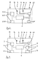
- the structure of the oxygen activation device 3 is apparent from Figures 2 and 3, wherein here two different embodiments are shown schematically.
- the oxygen activation device 3 according to FIG. 2, like the one according to FIG. 3, consists of a housing 7, which is configured substantially parallelepipedic.
- the housing 7 gives the oxygen activation device 3 a compact design, i. H. the device 3 is designed as a compact unit. It takes in air from the ventilation system 1 and releases it to the room 2 after the oxygen enrichment.
- the device 3 For oxygen enrichment, the device 3 according to FIG. 2 has means 4 and 5, respectively. These means can be designed either for ion generation (means 4) or for ozone production (means 5).
- an ion generator 8 is provided, which is in communication with a high voltage generator 9 and receives from it the energy for ion generation.
- an ozone generator 10 is provided which communicates with a high voltage generator 11.
- the high voltage generator 9, 11 draws the required energy from a storage means 6 for electrical energy, d. H. in the present case of a rechargeable battery (accumulator).
- accumulator a 12 volt accumulator that can work on any basis (dry battery or liquid (acid) battery).
- the charging status of the accumulator 6 can be displayed via signal means 12 and 13.
- the signal means 12 is designed as a lamp or light-emitting diode for the optical display.
- the additional Signaling means 13 are designed as acoustic signaling means.
- further signal means 14 can be provided, for example in the form of one or more lamps or light-emitting diodes, which indicate the operating state or mode of operation of the device 3.
- the control of the signal means 12, 13, 14 is effected by an electronics 20 which is in communication with the accumulator 6.
- an air flow monitoring device 21 may be provided, which is in operative connection with a sensor for direct or indirect determination of the air flow.
- This sensor can be designed as a pressure or speed sensor.
- the air flow monitoring device 21 causes control of the ion generator 8 or ozone generator 10 on the basis of the signals from the sensor.
- the control may comprise a simple switching on or off or also a setting, in particular continuous adjustment of the ion generation or ozone production rate.
- the signaling means 12, 13, 14 can indicate it, for example, when the accumulator 6 only has a low charge status or no charge at all.
- the signaling means 14 can in particular indicate the operating state of the device 3 by means of differently colored light-emitting diodes.
- the housing 7 is designed as an EMC-tested module housing.
Landscapes
- Engineering & Computer Science (AREA)
- Chemical & Material Sciences (AREA)
- Combustion & Propulsion (AREA)
- Mechanical Engineering (AREA)
- General Engineering & Computer Science (AREA)
- Health & Medical Sciences (AREA)
- General Health & Medical Sciences (AREA)
- Animal Behavior & Ethology (AREA)
- Life Sciences & Earth Sciences (AREA)
- Epidemiology (AREA)
- Public Health (AREA)
- Veterinary Medicine (AREA)
- Toxicology (AREA)
- Disinfection, Sterilisation Or Deodorisation Of Air (AREA)
- Central Air Conditioning (AREA)
- Treating Waste Gases (AREA)
Applications Claiming Priority (1)
| Application Number | Priority Date | Filing Date | Title |
|---|---|---|---|
| DE102006008265.6A DE102006008265B4 (de) | 2006-02-22 | 2006-02-22 | Verfahren und Vorrichtung zur Aufbereitung eines Luftstroms |
Publications (2)
| Publication Number | Publication Date |
|---|---|
| EP1826497A2 true EP1826497A2 (fr) | 2007-08-29 |
| EP1826497A3 EP1826497A3 (fr) | 2009-06-17 |
Family
ID=37963578
Family Applications (1)
| Application Number | Title | Priority Date | Filing Date |
|---|---|---|---|
| EP07102453A Withdrawn EP1826497A3 (fr) | 2006-02-22 | 2007-02-15 | Procédé de préparation d'un flux d'air introduit dans l'espace d'un bâtiment par une installation de ventilation |
Country Status (2)
| Country | Link |
|---|---|
| EP (1) | EP1826497A3 (fr) |
| DE (1) | DE102006008265B4 (fr) |
Cited By (1)
| Publication number | Priority date | Publication date | Assignee | Title |
|---|---|---|---|---|
| CN106765829A (zh) * | 2016-12-02 | 2017-05-31 | 沈阳建筑大学 | 一种智能通风箱 |
Families Citing this family (6)
| Publication number | Priority date | Publication date | Assignee | Title |
|---|---|---|---|---|
| DE102008041161A1 (de) | 2008-08-11 | 2010-02-18 | BSH Bosch und Siemens Hausgeräte GmbH | Luftaufbereitungsvorrichtung und Dunstabzugsvorrichtung |
| DE102008054775A1 (de) | 2008-12-16 | 2010-06-17 | BSH Bosch und Siemens Hausgeräte GmbH | Luftaufbereitungsvorrichtung und Verfahren zum Detektieren eines Filterelementes in einer Luftaufbereitungsvorrichtung |
| DE102008054780A1 (de) | 2008-12-16 | 2010-06-17 | BSH Bosch und Siemens Hausgeräte GmbH | Zusatzgerät für eine Dunstabzugshaube, insbesondere Luftaufbereitungsvorrichtung |
| DE102011081301A1 (de) | 2011-08-22 | 2013-02-28 | BSH Bosch und Siemens Hausgeräte GmbH | Luftaufbereitungsvorrichtung und Dunstabzugsvorrichtung |
| CN109186012A (zh) * | 2018-11-12 | 2019-01-11 | 张学锋 | 一种健康空气获取装置 |
| WO2024000716A1 (fr) * | 2022-06-30 | 2024-01-04 | 广东美的制冷设备有限公司 | Climatiseur et procédé de commande correspondant |
Family Cites Families (7)
| Publication number | Priority date | Publication date | Assignee | Title |
|---|---|---|---|---|
| US3438180A (en) * | 1965-12-28 | 1969-04-15 | Trane Co | Air-cleaning apparatus |
| DE4213778C2 (de) * | 1991-10-30 | 1994-02-24 | Kesslertech Gmbh | Verfahren und Klimaanlage zur Aufbereitung von Raumluft für den Humanbereich |
| DK0567775T3 (da) * | 1992-04-28 | 1995-12-04 | Humanair Patentverwertung Gmbh | Fremgangsmåde til behandling af rumluft for humanområdet |
| US5667564A (en) * | 1996-08-14 | 1997-09-16 | Wein Products, Inc. | Portable personal corona discharge device for destruction of airborne microbes and chemical toxins |
| US6432367B1 (en) * | 1997-02-28 | 2002-08-13 | Michael Munk | Indoor air quality gas phase return air cleaner |
| US6668563B2 (en) * | 2002-02-09 | 2003-12-30 | Bernard J. Mirowsky | Air treatment system for airplanes |
| EP1440695B1 (fr) * | 2003-01-21 | 2009-07-01 | Helmut Dipl.-Ing. Siegmund | Dispositif pour activer l'oxygène provenant de l'air pour la destruction de COVs et des germes ainsi que pour maintenir des concentrations en oxygène et en ozone égales à celles rencontrées dans la nature |
-
2006
- 2006-02-22 DE DE102006008265.6A patent/DE102006008265B4/de not_active Expired - Lifetime
-
2007
- 2007-02-15 EP EP07102453A patent/EP1826497A3/fr not_active Withdrawn
Cited By (2)
| Publication number | Priority date | Publication date | Assignee | Title |
|---|---|---|---|---|
| CN106765829A (zh) * | 2016-12-02 | 2017-05-31 | 沈阳建筑大学 | 一种智能通风箱 |
| CN106765829B (zh) * | 2016-12-02 | 2022-08-05 | 沈阳建筑大学 | 一种智能通风箱 |
Also Published As
| Publication number | Publication date |
|---|---|
| EP1826497A3 (fr) | 2009-06-17 |
| DE102006008265B4 (de) | 2017-09-14 |
| DE102006008265A1 (de) | 2007-08-23 |
Similar Documents
| Publication | Publication Date | Title |
|---|---|---|
| EP1826497A2 (fr) | Procédé de préparation d'un flux d'air introduit dans l'espace d'un bâtiment par une installation de ventilation | |
| DE60300751T2 (de) | Sauerstoff- und Inertgasgenerator | |
| EP3582841B1 (fr) | Dispositif de respiration avec un élément de position de souffleur et structure de conduite | |
| EP0536546A1 (fr) | Appareil respiratoire assisté par un ventilateur avec organe de commande attachable | |
| DE2635532A1 (de) | Beatmungsgeraet fuer die behandlung bei ungenuegender atmung | |
| CH708655A1 (de) | Luftreinigungsgerät mit Ozon- und Feinstaubreinigung. | |
| DE29911519U1 (de) | Klimaanlage für ein Kraftfahrzeug und Kraftfahrzeug mit einer Klimaanlage | |
| CH715036B1 (de) | Vorrichtung zur Luftversorgung einer Brennstoffzelle, vorzugsweise einer mit Wasserstoff betriebenen, Brennstoffzelle. | |
| DE2252373A1 (de) | Vorrichtung zum verhindern, dass ein betrunkener einen kraftwagen faehrt | |
| DE20200574U1 (de) | Luftreinigungsvorrichtung für Fahrzeuge | |
| DE102014102826A1 (de) | Kraftfahrzeug | |
| DE102008059003B4 (de) | Radiallüfter | |
| DE19531916A1 (de) | Verfahren und Vorrichtung zur Bereitstellung von Atemgas in Notsauerstoffsystemen | |
| WO2001027541A9 (fr) | Procede de climatisation d'espace clos | |
| DE102017001202A1 (de) | Luftreinigungsvorrichtung und Kraftfahrzeug | |
| EP3242824A1 (fr) | Véhicule ferroviaire comprenant un système de refroidissement de traction | |
| EP2790742B1 (fr) | Appareil de purification de l'air ambiant avex generateur du plasma et ecoulement radiale | |
| DE202013105538U1 (de) | Vorrichtung zur Erwärmung von Gas in einem Gerät, insbesondere zur Erwärmung von Atemgas | |
| DE1261295B (de) | Geraet zur Einstellung des Ionengehaltes der in Wohnraeumen enthaltenen Luft | |
| DE102005048645B4 (de) | Pneumatische Anordnung zur Druckluftaufbereitung | |
| DE102010024265A1 (de) | Belüftungseinrichtung für eine Passagerkabine | |
| DE102006043770B3 (de) | Duschvorrichtung | |
| DE2355544A1 (de) | Einrichtung fuer personenfahrzeuge, insbesondere personenwagen und omnibusse zur verbesserung der luft im innenraum | |
| DE102016214076A1 (de) | Ladeluftkühler | |
| EP1816410A1 (fr) | Procédure et appareil pour réfrigérer un écoulement d'air par humidification d'air sortant |
Legal Events
| Date | Code | Title | Description |
|---|---|---|---|
| PUAI | Public reference made under article 153(3) epc to a published international application that has entered the european phase |
Free format text: ORIGINAL CODE: 0009012 |
|
| AK | Designated contracting states |
Kind code of ref document: A2 Designated state(s): AT BE BG CH CY CZ DE DK EE ES FI FR GB GR HU IE IS IT LI LT LU LV MC NL PL PT RO SE SI SK TR |
|
| AX | Request for extension of the european patent |
Extension state: AL BA HR MK YU |
|
| PUAL | Search report despatched |
Free format text: ORIGINAL CODE: 0009013 |
|
| RAP1 | Party data changed (applicant data changed or rights of an application transferred) |
Owner name: GSB MBH Owner name: LASKOWSKI, RAINER, DIPL.-ING. |
|
| RIN1 | Information on inventor provided before grant (corrected) |
Inventor name: GSB MBH Inventor name: LASKOWSKI, RAINER, DIPL.-ING. |
|
| AK | Designated contracting states |
Kind code of ref document: A3 Designated state(s): AT BE BG CH CY CZ DE DK EE ES FI FR GB GR HU IE IS IT LI LT LU LV MC NL PL PT RO SE SI SK TR |
|
| AX | Request for extension of the european patent |
Extension state: AL BA HR MK RS |
|
| RIC1 | Information provided on ipc code assigned before grant |
Ipc: A61L 9/015 20060101ALI20090512BHEP Ipc: B03C 3/41 20060101ALI20090512BHEP Ipc: F24F 3/16 20060101AFI20070502BHEP |
|
| RIN1 | Information on inventor provided before grant (corrected) |
Inventor name: LEHMANN, JOERG Inventor name: KOLB, THOMAS Inventor name: LASKOWSKI, RAINER |
|
| 17P | Request for examination filed |
Effective date: 20091216 |
|
| AKX | Designation fees paid |
Designated state(s): AT BE BG CH CY CZ DE DK EE ES FI FR GB GR HU IE IS IT LI LT LU LV MC NL PL PT RO SE SI SK TR |
|
| 17Q | First examination report despatched |
Effective date: 20100205 |
|
| RAP1 | Party data changed (applicant data changed or rights of an application transferred) |
Owner name: GSB MBH |
|
| STAA | Information on the status of an ep patent application or granted ep patent |
Free format text: STATUS: THE APPLICATION IS DEEMED TO BE WITHDRAWN |
|
| 18D | Application deemed to be withdrawn |
Effective date: 20120901 |