EP1826503A2 - Kit zur Verteilung, Verwaltung und Messung der Energie in einem solarbetriebenen System, das mit anderen Energiequellen verbunden sein kann - Google Patents
Kit zur Verteilung, Verwaltung und Messung der Energie in einem solarbetriebenen System, das mit anderen Energiequellen verbunden sein kann Download PDFInfo
- Publication number
- EP1826503A2 EP1826503A2 EP07103258A EP07103258A EP1826503A2 EP 1826503 A2 EP1826503 A2 EP 1826503A2 EP 07103258 A EP07103258 A EP 07103258A EP 07103258 A EP07103258 A EP 07103258A EP 1826503 A2 EP1826503 A2 EP 1826503A2
- Authority
- EP
- European Patent Office
- Prior art keywords
- boiler
- solar
- fireplace
- energy
- management
- Prior art date
- Legal status (The legal status is an assumption and is not a legal conclusion. Google has not performed a legal analysis and makes no representation as to the accuracy of the status listed.)
- Granted
Links
Images



Classifications
-
- F—MECHANICAL ENGINEERING; LIGHTING; HEATING; WEAPONS; BLASTING
- F24—HEATING; RANGES; VENTILATING
- F24D—DOMESTIC- OR SPACE-HEATING SYSTEMS, e.g. CENTRAL HEATING SYSTEMS; DOMESTIC HOT-WATER SUPPLY SYSTEMS; ELEMENTS OR COMPONENTS THEREFOR
- F24D3/00—Hot-water central heating systems
- F24D3/10—Feed-line arrangements, e.g. providing for heat-accumulator tanks, expansion tanks ; Hydraulic components of a central heating system
-
- F—MECHANICAL ENGINEERING; LIGHTING; HEATING; WEAPONS; BLASTING
- F24—HEATING; RANGES; VENTILATING
- F24D—DOMESTIC- OR SPACE-HEATING SYSTEMS, e.g. CENTRAL HEATING SYSTEMS; DOMESTIC HOT-WATER SUPPLY SYSTEMS; ELEMENTS OR COMPONENTS THEREFOR
- F24D11/00—Central heating systems using heat accumulated in storage masses
- F24D11/002—Central heating systems using heat accumulated in storage masses water heating system
- F24D11/003—Central heating systems using heat accumulated in storage masses water heating system combined with solar energy
-
- F—MECHANICAL ENGINEERING; LIGHTING; HEATING; WEAPONS; BLASTING
- F24—HEATING; RANGES; VENTILATING
- F24D—DOMESTIC- OR SPACE-HEATING SYSTEMS, e.g. CENTRAL HEATING SYSTEMS; DOMESTIC HOT-WATER SUPPLY SYSTEMS; ELEMENTS OR COMPONENTS THEREFOR
- F24D11/00—Central heating systems using heat accumulated in storage masses
- F24D11/002—Central heating systems using heat accumulated in storage masses water heating system
- F24D11/004—Central heating systems using heat accumulated in storage masses water heating system with conventional supplementary heat source
-
- F—MECHANICAL ENGINEERING; LIGHTING; HEATING; WEAPONS; BLASTING
- F24—HEATING; RANGES; VENTILATING
- F24D—DOMESTIC- OR SPACE-HEATING SYSTEMS, e.g. CENTRAL HEATING SYSTEMS; DOMESTIC HOT-WATER SUPPLY SYSTEMS; ELEMENTS OR COMPONENTS THEREFOR
- F24D12/00—Other central heating systems
- F24D12/02—Other central heating systems having more than one heat source
-
- F—MECHANICAL ENGINEERING; LIGHTING; HEATING; WEAPONS; BLASTING
- F24—HEATING; RANGES; VENTILATING
- F24D—DOMESTIC- OR SPACE-HEATING SYSTEMS, e.g. CENTRAL HEATING SYSTEMS; DOMESTIC HOT-WATER SUPPLY SYSTEMS; ELEMENTS OR COMPONENTS THEREFOR
- F24D19/00—Details
- F24D19/10—Arrangement or mounting of control or safety devices
- F24D19/1006—Arrangement or mounting of control or safety devices for water heating systems
- F24D19/1009—Arrangement or mounting of control or safety devices for water heating systems for central heating
-
- F—MECHANICAL ENGINEERING; LIGHTING; HEATING; WEAPONS; BLASTING
- F24—HEATING; RANGES; VENTILATING
- F24D—DOMESTIC- OR SPACE-HEATING SYSTEMS, e.g. CENTRAL HEATING SYSTEMS; DOMESTIC HOT-WATER SUPPLY SYSTEMS; ELEMENTS OR COMPONENTS THEREFOR
- F24D19/00—Details
- F24D19/0097—Casings or frame structures for hydraulic components
-
- F—MECHANICAL ENGINEERING; LIGHTING; HEATING; WEAPONS; BLASTING
- F24—HEATING; RANGES; VENTILATING
- F24D—DOMESTIC- OR SPACE-HEATING SYSTEMS, e.g. CENTRAL HEATING SYSTEMS; DOMESTIC HOT-WATER SUPPLY SYSTEMS; ELEMENTS OR COMPONENTS THEREFOR
- F24D2200/00—Heat sources or energy sources
- F24D2200/04—Gas or oil fired boiler
-
- F—MECHANICAL ENGINEERING; LIGHTING; HEATING; WEAPONS; BLASTING
- F24—HEATING; RANGES; VENTILATING
- F24D—DOMESTIC- OR SPACE-HEATING SYSTEMS, e.g. CENTRAL HEATING SYSTEMS; DOMESTIC HOT-WATER SUPPLY SYSTEMS; ELEMENTS OR COMPONENTS THEREFOR
- F24D2200/00—Heat sources or energy sources
- F24D2200/10—Fire place
-
- F—MECHANICAL ENGINEERING; LIGHTING; HEATING; WEAPONS; BLASTING
- F24—HEATING; RANGES; VENTILATING
- F24D—DOMESTIC- OR SPACE-HEATING SYSTEMS, e.g. CENTRAL HEATING SYSTEMS; DOMESTIC HOT-WATER SUPPLY SYSTEMS; ELEMENTS OR COMPONENTS THEREFOR
- F24D2200/00—Heat sources or energy sources
- F24D2200/14—Solar energy
-
- Y—GENERAL TAGGING OF NEW TECHNOLOGICAL DEVELOPMENTS; GENERAL TAGGING OF CROSS-SECTIONAL TECHNOLOGIES SPANNING OVER SEVERAL SECTIONS OF THE IPC; TECHNICAL SUBJECTS COVERED BY FORMER USPC CROSS-REFERENCE ART COLLECTIONS [XRACs] AND DIGESTS
- Y02—TECHNOLOGIES OR APPLICATIONS FOR MITIGATION OR ADAPTATION AGAINST CLIMATE CHANGE
- Y02B—CLIMATE CHANGE MITIGATION TECHNOLOGIES RELATED TO BUILDINGS, e.g. HOUSING, HOUSE APPLIANCES OR RELATED END-USER APPLICATIONS
- Y02B10/00—Integration of renewable energy sources in buildings
- Y02B10/20—Solar thermal
-
- Y—GENERAL TAGGING OF NEW TECHNOLOGICAL DEVELOPMENTS; GENERAL TAGGING OF CROSS-SECTIONAL TECHNOLOGIES SPANNING OVER SEVERAL SECTIONS OF THE IPC; TECHNICAL SUBJECTS COVERED BY FORMER USPC CROSS-REFERENCE ART COLLECTIONS [XRACs] AND DIGESTS
- Y02—TECHNOLOGIES OR APPLICATIONS FOR MITIGATION OR ADAPTATION AGAINST CLIMATE CHANGE
- Y02B—CLIMATE CHANGE MITIGATION TECHNOLOGIES RELATED TO BUILDINGS, e.g. HOUSING, HOUSE APPLIANCES OR RELATED END-USER APPLICATIONS
- Y02B10/00—Integration of renewable energy sources in buildings
- Y02B10/70—Hybrid systems, e.g. uninterruptible or back-up power supplies integrating renewable energies
-
- Y—GENERAL TAGGING OF NEW TECHNOLOGICAL DEVELOPMENTS; GENERAL TAGGING OF CROSS-SECTIONAL TECHNOLOGIES SPANNING OVER SEVERAL SECTIONS OF THE IPC; TECHNICAL SUBJECTS COVERED BY FORMER USPC CROSS-REFERENCE ART COLLECTIONS [XRACs] AND DIGESTS
- Y02—TECHNOLOGIES OR APPLICATIONS FOR MITIGATION OR ADAPTATION AGAINST CLIMATE CHANGE
- Y02B—CLIMATE CHANGE MITIGATION TECHNOLOGIES RELATED TO BUILDINGS, e.g. HOUSING, HOUSE APPLIANCES OR RELATED END-USER APPLICATIONS
- Y02B30/00—Energy efficient heating, ventilation or air conditioning [HVAC]
Definitions
- the present invention basically relates to the sector of thermal systems for exploitation of solar energy.
- Solar-heating systems are normally constituted by a solar circuit, comprising at least one solar panel and pipes for delivery and return of the thermal-carrier fluid, as well as a series of devices designed to control the distribution, management, measurement and metering of energy in the solar-heating system, also in relation to other energy sources used in said system, such as for example a fireplace-boiler and/or a boiler.
- a problem that is common to said known heating systems is represented by the fact that said control devices must be properly installed, configured and calibrated both with respect to one another and with respect to the system on which they are to act.
- a second problem of the known art is represented by the fact that said control devices must be installed by qualified staff having a knowledge of the problems of each of said devices, which differ according to whether they are devices for management, measurement and metering, or distribution of energy.
- a further problem of current solar-heating systems consists in the difficulty of managing the other energy sources appropriately in order to guarantee full exploitation of the contribution coming from the solar-heating system when the latter is available.
- the main purpose of the present invention is to provide a single apparatus or kit, comprised in which are all or part of said control devices, according to the requirements of the system, said control devices being already installed in compliance with the law and tested in the factory, thus guaranteeing proper operation and enabling rapid and immediate installation of the kit.
- kit comprising a container, which contains said control devices and is designed to be installed by means of simple connection of the delivery and return pipes of the solar circuit and of the possible circuit for expulsion and recovery of the thermal-carrier fluid, as well as of the connection cables for electrical supply and for the usual probes.
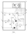
- FIGS 1 to 4 regard embodiments that envisage management of just solar energy as source of heat for heating water to be used for sanitary purposes, whilst the subsequent figures regard embodiments in which the solar source is backed up, if necessary, by other sources of heat, such as for example a fireplace-boiler and/or a boiler both for heating water for sanitary purposes and for heating environments.
- the kit that is described gathers together, already preassembled, all the hydraulic and electronic devices for distribution, management, measurement and metering of the energy in a solar-heating system and other energy sources for thermal integration.
- the invention presents as a kit made up of a cabinet 1 with a door, inside which the necessary control devices are housed and installed.
- the interface of the kit with the outside world is advantageously constituted by the electrical connection cables 6 for power supply and for the probes, and by the connectors 7, set laterally, for connection to the delivery and return pipes of the solar-heating system and to the pipe for expulsion and recovery of the thermal-carrier fluid following upon conditions of overpressure.
- the components of the kit are:
- the hydronic unit according to the present invention has been devised and built to provide the customer and the installer with a complete unit that is simple to apply on the solar-heating system.
- the hydronic unit envisages, in addition to proper positioning of the delivery and return branches of the solar-heating system and of the other possible energy sources, nonreturn valves VR, three-way valves VM, and safety and circulation devices, thus enabling measurement and possible monitoring of the temperatures of the heating system and the operating pressure.
- These data, processed by the electronic control unit 4 enable control of the circulator and hence of the heat exchange between the solar panels and the storage tank.
- the presence of the volumetric meter CV enables monitoring of the amount of fluid circulating in the heating system, thus enabling evaluations of an energy type of the levels of consumption of the appliances served by the hydronic unit.
- the above evaluations can be made electronically by the energy-measuring device 5, which analyses the input data of the volumetric meter CV and of the temperature probes T.
- the use of the invention enables a convenient management of the data in order to enable a local and/or remote monitoring of the solar-heating system (in the case of remote monitoring, a connection to a modem or other similar device is necessary).
- the hydronic unit contains within it also an assembly for automatic charging, which enables recovery of the thermal-carrier liquid, that has been dissipated by the safety valve VS of the solar circuit during maximum expansion, in this way guaranteeing a constant pressure in the solar circuit and its adaptability to the various conditions of operation in time.
- a series of control circuits is provided, which set in connection the storage tanks referred to both with the solar collectors and with a fireplace-boiler and a traditional boiler.
- This circuitry has the task of bringing about intervention, in sequence, first of the solar-heating system, then of the fireplace-boiler, and lastly of the boiler.
- the intervention of the boiler does not act on the entire storage tank but only on its upper part (i.e., the hottest part) or else, alternatively, it can provide the heating directly to the user.
- the presence of the electronic control unit 4 also enables management, through the hydronic unit described herein, of the various energy sources.
- the hydronic unit in its most complete version, performs four functions:
- Figure 2 shows a second embodiment of the invention, which manages just the solar energy for heating water for sanitary purposes, in which the function of energy measurement and metering is absent.
- the electronic energy-measuring device 5 and the temperature probes T on the delivery and return branches of the solar circuit are absent, and said probes are replaced by analogical thermometers.
- Figure 3 shows a third embodiment, which differs from that of Figure 1 on account of the absence of the automatic filling device.
- Figure 4 shows a fourth particularly simple embodiment, in which the sole function performed is that of automatic and electronic management of the solar circuit.
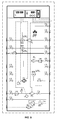
- Figures 5 and 8 show the most complete embodiment of the invention, in which there are comprised, in addition to the already described functions regarding management of the solar-heating system for supply of hot water, also those for management of a number of energy sources for serving a system for producing hot water for sanitary purposes and for heating premises.
- Present in Figures 5 to 10 are two boilers: a first boiler B1 for hot water for sanitary purposes and a second boiler B2 for heating (which functions as "thermal fly-wheel"), in which hot water that is to be sent to heating circuits (radiators or radiant floors) is accumulated.
- the two boilers B1 and B2 are equipped with two heat exchangers, one for the solar-energy source in the bottom part, and one for integration with another energy source in the top part.
- Main components solar collectors, closed-vessel fireplace-boiler, radiators or radiant floor, a first boiler B1 for hot water for sanitary purposes, a second boiler B2 or thermal fly-wheel for heating purposes, all of which connected to one and the same hydronic unit 1.
- the circulator P2 of the fireplace-boiler is active (ON) and, through the deviating valve VM3 of the fireplace-boiler, is set for carrying energy from the fireplace-boiler to the boiler for sanitary purposes B1.
- the motor-driven deviating valves of the fireplace-boiler VM3 and of the radiators VM2 are set for connecting the system of the fireplace-boiler directly to the radiators.
- the motor-driven deviating valve VM1 enables connection of the fireplace-boiler with the heat exchanger SC set in the upper part of the second boiler B2 for heating.
- the second boiler B2 (with function of thermal fly-wheel) accumulates thermal energy from the fireplace-boiler in addition to the energy supplied thereto by the solar-heating system, providing a stratification of the temperatures within it.
- the motor-driven deviating valve VM1 is connected to the radiators and the motor-driven deviating valve VM2 is connected to the second boiler B2, thus enabling transfer of the heat accumulated, produced by the solar source and/or by the fireplace-boiler, to the heating system.
- the motor-driven deviating valve VM4 is configured for connecting the boiler circuit to the radiators. In this situation, the integration of the hot water for sanitary purposes occurs in the boiler via the motor-driven deviating valve VM5 (not included in the Domino).
- the temperature of delivery to the radiators which determines the values of temperature indicated for intervention of the various devices, is defined by the value set by the user (according to the type of the radiators) on the thermostatic mixing valve MT comprised in the Domino.
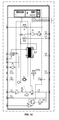
- Figures 6 and 9 show a sixth embodiment, which is the most suitable for heating systems that have low-temperature radiators ( ⁇ 40°C) .
- the fireplace-boiler can supply its energy to the first boiler B1 for water for sanitary purposes or else to the second boiler B2 for heating, adding its energy to the energy supplied by the solar collectors.
- the fly-wheel supplies energy to the radiators.
- the boiler supplies energy to the heating system.
- a seventh embodiment of the invention envisages that, provided within the hydronic unit is a plate-type heat exchanger SP, designed to enable interfacing of the closed-vessel system of the traditional boiler and the open-vessel system of the fireplace-boiler.
- thermometer TC for enabling display of the temperatures T1 and T2 and a LED.
- the user does not need to light the fireplace-boiler because the second boiler B2 is ready to supply energy to the system. If the fireplace-boiler is already lit, it is not necessary to continue to supply it.
- the user lights the fireplace-boiler, then the circulator P2 is activated, and the motor-driven deviating valve VM3 is positioned for giving precedence to the first boiler B1.
- the user lights the fireplace-boiler, then the circulator P2 is activated, the deviating valve VM3 deviates to the plate-type heat exchanger SP, the circulator P4 is activated, and the deviating valve VM2 sends the energy produced by the fireplace-boiler directly to radiators.
- the circulator or pump P4 is turned off, and the boiler and the corresponding pump P3 are turned on.
- the area valve VZ enables the delivery of heat from the boiler directly to the radiators.
Landscapes
- Engineering & Computer Science (AREA)
- Physics & Mathematics (AREA)
- Thermal Sciences (AREA)
- Chemical & Material Sciences (AREA)
- Combustion & Propulsion (AREA)
- Mechanical Engineering (AREA)
- General Engineering & Computer Science (AREA)
- Sustainable Development (AREA)
- Life Sciences & Earth Sciences (AREA)
- Sustainable Energy (AREA)
- Arrangements For Transmission Of Measured Signals (AREA)
- Heat-Pump Type And Storage Water Heaters (AREA)
- Photometry And Measurement Of Optical Pulse Characteristics (AREA)
- Investigating Or Analyzing Materials Using Thermal Means (AREA)
- Financial Or Insurance-Related Operations Such As Payment And Settlement (AREA)
- Management, Administration, Business Operations System, And Electronic Commerce (AREA)
Priority Applications (2)
| Application Number | Priority Date | Filing Date | Title |
|---|---|---|---|
| PL07103258T PL1826503T3 (pl) | 2006-02-28 | 2007-02-28 | Zestaw do dystrybucji, zarządzania, pomiaru i dozowania energii w układzie ogrzewania słonecznego, mogący być powiązanym z innymi źródłami energii |
| SI200730687T SI1826503T1 (sl) | 2006-02-28 | 2007-02-28 | Enota za distribucijo, upravljanje, merjenje energije v solarnem sistemu za ogrevanje, z moĺ˝nostjo povezave z drugimi viri energije |
Applications Claiming Priority (1)
| Application Number | Priority Date | Filing Date | Title |
|---|---|---|---|
| IT000035U ITRM20060035U1 (it) | 2006-02-28 | 2006-02-28 | Kit per la distribuzione la gestione e la contabilizzazione di un impianto solare |
Publications (3)
| Publication Number | Publication Date |
|---|---|
| EP1826503A2 true EP1826503A2 (de) | 2007-08-29 |
| EP1826503A3 EP1826503A3 (de) | 2008-03-19 |
| EP1826503B1 EP1826503B1 (de) | 2011-05-11 |
Family
ID=38162322
Family Applications (1)
| Application Number | Title | Priority Date | Filing Date |
|---|---|---|---|
| EP07103258A Not-in-force EP1826503B1 (de) | 2006-02-28 | 2007-02-28 | Kit zur Verteilung, Verwaltung und Messung der Energie in einem solarbetriebenen System, das mit anderen Energiequellen verbunden sein kann |
Country Status (5)
| Country | Link |
|---|---|
| EP (1) | EP1826503B1 (de) |
| AT (1) | ATE509243T1 (de) |
| IT (1) | ITRM20060035U1 (de) |
| PL (1) | PL1826503T3 (de) |
| SI (1) | SI1826503T1 (de) |
Cited By (14)
| Publication number | Priority date | Publication date | Assignee | Title |
|---|---|---|---|---|
| FR2921471A1 (fr) * | 2007-09-21 | 2009-03-27 | Hades Soc Par Actions Simplifi | Boitier repartiteur de fluide caloporteur, pour le couplage d'une pompe a chaleur a une pluralite de circuits de captage et de distribution de chaleur |
| FR2925950A1 (fr) * | 2007-12-26 | 2009-07-03 | Jean Luc Bouvier | Installation de chauffage domestique mixte, solaire, bois et electrique |
| FR2927152A1 (fr) * | 2008-02-04 | 2009-08-07 | Airpac Sarl | Dispositif de transfert de chaleur comprenant une enceinte pre-equipee. |
| WO2010053798A1 (en) * | 2008-10-28 | 2010-05-14 | Trak International, Llc | Methods and equipment for heating and cooling building zones |
| EP1962022A3 (de) * | 2006-09-13 | 2012-02-01 | Leako, S.L. | Kasten zur Verteilung, Messung und Herstellung von sanitärem Wasser und Heizung |
| CN103090442A (zh) * | 2013-02-18 | 2013-05-08 | 洛阳万山高新技术应用工程有限公司 | 环保节能采暖系统 |
| EP2498008A3 (de) * | 2011-03-10 | 2014-07-16 | Michael Hertneck | Flächenheizeinrichtung und Anschlussbox |
| CN103994488A (zh) * | 2014-05-28 | 2014-08-20 | 原建新 | 一种多功能采暖装置及其采暖方法 |
| CN104728902A (zh) * | 2013-12-24 | 2015-06-24 | 唐山长虹塑料制品有限公司 | 一种供暖系统 |
| FR3034850A1 (fr) * | 2015-04-13 | 2016-10-14 | Infiniti Energies | Kit modulaire de montage d'une installation de production d'eau chaude sanitaire et installation realisee a partir d'un tel kit |
| EP3546839A1 (de) * | 2018-03-26 | 2019-10-02 | Mitsubishi Electric R&D Centre Europe B.V. | Modulare führungseinrichtung für eine konfigurierbare fluidische kopplung von drei funktionellen vorrichtungen mit heiz- und/oder kühlkreisläufen |
| IT201800011102A1 (it) * | 2018-12-14 | 2020-06-14 | Paolo Picciafuoco | Sistema modulare di distribuzione idraulica multi-accumulo |
| KR102591422B1 (ko) * | 2023-01-04 | 2023-10-19 | 극동에너지 주식회사 | 열교환이 용이한 태양열 난방장치 |
| WO2024022845A1 (fr) | 2022-07-26 | 2024-02-01 | BAUVIR, François | Kit d'adaptation pour une installation de chauffage central et procédé de pilotage d'une installation équipée d'un tel kit |
Family Cites Families (3)
| Publication number | Priority date | Publication date | Assignee | Title |
|---|---|---|---|---|
| DE3245416A1 (de) * | 1982-12-08 | 1984-08-16 | Strelow, geb. Schumacher, Roswitha, 4000 Düsseldorf | Energietauschersystem |
| CA2091949C (en) * | 1992-03-19 | 1997-03-04 | Josef Dumser | Device for supplying a circuit of a heating or cooling supply system |
| DE20019953U1 (de) * | 2000-11-24 | 2002-03-28 | Heckmeier, Josef, 85301 Schweitenkirchen | Zentraleinheit zur Wärmeverteilung in Heizungsanlagen |
-
2006
- 2006-02-28 IT IT000035U patent/ITRM20060035U1/it unknown
-
2007
- 2007-02-28 EP EP07103258A patent/EP1826503B1/de not_active Not-in-force
- 2007-02-28 AT AT07103258T patent/ATE509243T1/de active
- 2007-02-28 SI SI200730687T patent/SI1826503T1/sl unknown
- 2007-02-28 PL PL07103258T patent/PL1826503T3/pl unknown
Cited By (19)
| Publication number | Priority date | Publication date | Assignee | Title |
|---|---|---|---|---|
| EP1962022A3 (de) * | 2006-09-13 | 2012-02-01 | Leako, S.L. | Kasten zur Verteilung, Messung und Herstellung von sanitärem Wasser und Heizung |
| FR2921471A1 (fr) * | 2007-09-21 | 2009-03-27 | Hades Soc Par Actions Simplifi | Boitier repartiteur de fluide caloporteur, pour le couplage d'une pompe a chaleur a une pluralite de circuits de captage et de distribution de chaleur |
| WO2009071765A3 (fr) * | 2007-09-21 | 2009-08-13 | Hades | Installation de chauffage/climatisation à pompe à chaleur, comportant un boîtier répartiteur de fluide caloporteur avec couplage à une pluralité de circuits de captage et de distribution de chaleur |
| US8327655B2 (en) | 2007-09-21 | 2012-12-11 | Hades | Heating and air-conditioning installation with a heat pump, the installation including at least one heat transfer fluid distributor unit with coupling to a plurality of heat collection and delivery circuits |
| FR2925950A1 (fr) * | 2007-12-26 | 2009-07-03 | Jean Luc Bouvier | Installation de chauffage domestique mixte, solaire, bois et electrique |
| FR2927152A1 (fr) * | 2008-02-04 | 2009-08-07 | Airpac Sarl | Dispositif de transfert de chaleur comprenant une enceinte pre-equipee. |
| WO2010053798A1 (en) * | 2008-10-28 | 2010-05-14 | Trak International, Llc | Methods and equipment for heating and cooling building zones |
| EP2498008A3 (de) * | 2011-03-10 | 2014-07-16 | Michael Hertneck | Flächenheizeinrichtung und Anschlussbox |
| CN103090442A (zh) * | 2013-02-18 | 2013-05-08 | 洛阳万山高新技术应用工程有限公司 | 环保节能采暖系统 |
| CN104728902A (zh) * | 2013-12-24 | 2015-06-24 | 唐山长虹塑料制品有限公司 | 一种供暖系统 |
| CN104728902B (zh) * | 2013-12-24 | 2017-06-06 | 唐山长虹塑料制品有限公司 | 一种供暖系统 |
| CN103994488A (zh) * | 2014-05-28 | 2014-08-20 | 原建新 | 一种多功能采暖装置及其采暖方法 |
| CN103994488B (zh) * | 2014-05-28 | 2017-02-01 | 原建新 | 一种多功能采暖装置及其采暖方法 |
| FR3034850A1 (fr) * | 2015-04-13 | 2016-10-14 | Infiniti Energies | Kit modulaire de montage d'une installation de production d'eau chaude sanitaire et installation realisee a partir d'un tel kit |
| EP3546839A1 (de) * | 2018-03-26 | 2019-10-02 | Mitsubishi Electric R&D Centre Europe B.V. | Modulare führungseinrichtung für eine konfigurierbare fluidische kopplung von drei funktionellen vorrichtungen mit heiz- und/oder kühlkreisläufen |
| IT201800011102A1 (it) * | 2018-12-14 | 2020-06-14 | Paolo Picciafuoco | Sistema modulare di distribuzione idraulica multi-accumulo |
| WO2024022845A1 (fr) | 2022-07-26 | 2024-02-01 | BAUVIR, François | Kit d'adaptation pour une installation de chauffage central et procédé de pilotage d'une installation équipée d'un tel kit |
| FR3138505A1 (fr) * | 2022-07-26 | 2024-02-02 | Laurent BAUVIR | Couplage de plusieurs générateurs de chaleur pour installation de chauffage central |
| KR102591422B1 (ko) * | 2023-01-04 | 2023-10-19 | 극동에너지 주식회사 | 열교환이 용이한 태양열 난방장치 |
Also Published As
| Publication number | Publication date |
|---|---|
| EP1826503B1 (de) | 2011-05-11 |
| PL1826503T3 (pl) | 2011-12-30 |
| EP1826503A3 (de) | 2008-03-19 |
| ITRM20060035U1 (it) | 2007-09-01 |
| ATE509243T1 (de) | 2011-05-15 |
| SI1826503T1 (sl) | 2011-09-30 |
Similar Documents
| Publication | Publication Date | Title |
|---|---|---|
| EP1826503B1 (de) | Kit zur Verteilung, Verwaltung und Messung der Energie in einem solarbetriebenen System, das mit anderen Energiequellen verbunden sein kann | |
| US8720388B2 (en) | Demand management for water heaters | |
| AU2014246775B2 (en) | In-line heated solar thermal storage collector | |
| US10801751B2 (en) | Water consuming appliance and a method for operating the same | |
| GB2466075A (en) | Electric combination boiler | |
| WO2006111755A2 (en) | Hot water installations | |
| CN210569175U (zh) | 一种具有零冷水功能的新型分体式电热水器 | |
| EP1962022A2 (de) | Kasten zur Verteilung, Messung und Herstellung von sanitärem Wasser und Heizung | |
| EP2041496A1 (de) | Anordnung und verfahren zum ändern der temperatur eines ersten und eines zweiten fluids, die sich in getrennten behältern befinden | |
| CN102012062A (zh) | 一种电加热管采暖系统 | |
| KR101445266B1 (ko) | 냉난방을 위한 신재생에너지 중앙제어 연동관리시스템 | |
| EP2570738B1 (de) | Bedarfsverwaltung für Warmwasserbereiter | |
| US20210329741A1 (en) | Water heater appliances and methods for delayed activation | |
| CN108980954A (zh) | 一种节能省电的热泵供热系统及其控制方法 | |
| CN203240654U (zh) | 常压式水-水换热器 | |
| CN209481679U (zh) | 基于液态载质多能互补的恒温系统 | |
| CN213686968U (zh) | 一种智能混水换热机组 | |
| EP4563901A1 (de) | Wassererhitzer | |
| GB2505263A (en) | Fluid heating and storage system, ideally using a weather compensation boiler | |
| RU59789U1 (ru) | Коллектор с интегрированным смесительным узлом | |
| CN219264588U (zh) | 一种容积式热水器安装模块 | |
| EP4686881A1 (de) | Pumpstation für hybride heiz- oder kühlsysteme, hybrides heiz- oder kühlsystem und verfahren zur steuerung von hybriden heiz- und/oder kühlsystemen | |
| ES1325691U (es) | Sistema de alimentacion electrica para instalaciones de produccion de calor mediante energia fotovoltaica | |
| CA2753031C (en) | Demand management for water heaters | |
| WO2025087544A1 (en) | Heat pump coupling frame kit with energy monitoring |
Legal Events
| Date | Code | Title | Description |
|---|---|---|---|
| PUAI | Public reference made under article 153(3) epc to a published international application that has entered the european phase |
Free format text: ORIGINAL CODE: 0009012 |
|
| AK | Designated contracting states |
Kind code of ref document: A2 Designated state(s): AT BE BG CH CY CZ DE DK EE ES FI FR GB GR HU IE IS IT LI LT LU LV MC NL PL PT RO SE SI SK TR |
|
| AX | Request for extension of the european patent |
Extension state: AL BA HR MK YU |
|
| PUAL | Search report despatched |
Free format text: ORIGINAL CODE: 0009013 |
|
| AK | Designated contracting states |
Kind code of ref document: A3 Designated state(s): AT BE BG CH CY CZ DE DK EE ES FI FR GB GR HU IE IS IT LI LT LU LV MC NL PL PT RO SE SI SK TR |
|
| AX | Request for extension of the european patent |
Extension state: AL BA HR MK YU |
|
| 17P | Request for examination filed |
Effective date: 20080918 |
|
| AKX | Designation fees paid |
Designated state(s): AT BE BG CH CY CZ DE DK EE ES FI FR GB GR HU IE IS IT LI LT LU LV MC NL PL PT RO SE SI SK TR |
|
| 17Q | First examination report despatched |
Effective date: 20091119 |
|
| GRAJ | Information related to disapproval of communication of intention to grant by the applicant or resumption of examination proceedings by the epo deleted |
Free format text: ORIGINAL CODE: EPIDOSDIGR1 |
|
| GRAP | Despatch of communication of intention to grant a patent |
Free format text: ORIGINAL CODE: EPIDOSNIGR1 |
|
| GRAP | Despatch of communication of intention to grant a patent |
Free format text: ORIGINAL CODE: EPIDOSNIGR1 |
|
| RIN1 | Information on inventor provided before grant (corrected) |
Inventor name: RIZZO, LUIGI |
|
| GRAS | Grant fee paid |
Free format text: ORIGINAL CODE: EPIDOSNIGR3 |
|
| GRAA | (expected) grant |
Free format text: ORIGINAL CODE: 0009210 |
|
| AK | Designated contracting states |
Kind code of ref document: B1 Designated state(s): AT BE BG CH CY CZ DE DK EE ES FI FR GB GR HU IE IS IT LI LT LU LV MC NL PL PT RO SE SI SK TR |
|
| REG | Reference to a national code |
Ref country code: GB Ref legal event code: FG4D |
|
| REG | Reference to a national code |
Ref country code: CH Ref legal event code: EP |
|
| REG | Reference to a national code |
Ref country code: IE Ref legal event code: FG4D |
|
| REG | Reference to a national code |
Ref country code: DE Ref legal event code: R096 Ref document number: 602007014425 Country of ref document: DE Effective date: 20110622 |
|
| REG | Reference to a national code |
Ref country code: SE Ref legal event code: TRGR |
|
| REG | Reference to a national code |
Ref country code: NL Ref legal event code: VDEP Effective date: 20110511 |
|
| PG25 | Lapsed in a contracting state [announced via postgrant information from national office to epo] |
Ref country code: LT Free format text: LAPSE BECAUSE OF FAILURE TO SUBMIT A TRANSLATION OF THE DESCRIPTION OR TO PAY THE FEE WITHIN THE PRESCRIBED TIME-LIMIT Effective date: 20110511 Ref country code: PT Free format text: LAPSE BECAUSE OF FAILURE TO SUBMIT A TRANSLATION OF THE DESCRIPTION OR TO PAY THE FEE WITHIN THE PRESCRIBED TIME-LIMIT Effective date: 20110912 |
|
| PG25 | Lapsed in a contracting state [announced via postgrant information from national office to epo] |
Ref country code: CY Free format text: LAPSE BECAUSE OF FAILURE TO SUBMIT A TRANSLATION OF THE DESCRIPTION OR TO PAY THE FEE WITHIN THE PRESCRIBED TIME-LIMIT Effective date: 20110511 Ref country code: ES Free format text: LAPSE BECAUSE OF FAILURE TO SUBMIT A TRANSLATION OF THE DESCRIPTION OR TO PAY THE FEE WITHIN THE PRESCRIBED TIME-LIMIT Effective date: 20110822 Ref country code: LV Free format text: LAPSE BECAUSE OF FAILURE TO SUBMIT A TRANSLATION OF THE DESCRIPTION OR TO PAY THE FEE WITHIN THE PRESCRIBED TIME-LIMIT Effective date: 20110511 Ref country code: IS Free format text: LAPSE BECAUSE OF FAILURE TO SUBMIT A TRANSLATION OF THE DESCRIPTION OR TO PAY THE FEE WITHIN THE PRESCRIBED TIME-LIMIT Effective date: 20110911 Ref country code: GR Free format text: LAPSE BECAUSE OF FAILURE TO SUBMIT A TRANSLATION OF THE DESCRIPTION OR TO PAY THE FEE WITHIN THE PRESCRIBED TIME-LIMIT Effective date: 20110812 |
|
| PG25 | Lapsed in a contracting state [announced via postgrant information from national office to epo] |
Ref country code: NL Free format text: LAPSE BECAUSE OF FAILURE TO SUBMIT A TRANSLATION OF THE DESCRIPTION OR TO PAY THE FEE WITHIN THE PRESCRIBED TIME-LIMIT Effective date: 20110511 |
|
| REG | Reference to a national code |
Ref country code: PL Ref legal event code: T3 |
|
| PG25 | Lapsed in a contracting state [announced via postgrant information from national office to epo] |
Ref country code: CZ Free format text: LAPSE BECAUSE OF FAILURE TO SUBMIT A TRANSLATION OF THE DESCRIPTION OR TO PAY THE FEE WITHIN THE PRESCRIBED TIME-LIMIT Effective date: 20110511 Ref country code: EE Free format text: LAPSE BECAUSE OF FAILURE TO SUBMIT A TRANSLATION OF THE DESCRIPTION OR TO PAY THE FEE WITHIN THE PRESCRIBED TIME-LIMIT Effective date: 20110511 |
|
| PG25 | Lapsed in a contracting state [announced via postgrant information from national office to epo] |
Ref country code: RO Free format text: LAPSE BECAUSE OF FAILURE TO SUBMIT A TRANSLATION OF THE DESCRIPTION OR TO PAY THE FEE WITHIN THE PRESCRIBED TIME-LIMIT Effective date: 20110511 Ref country code: SK Free format text: LAPSE BECAUSE OF FAILURE TO SUBMIT A TRANSLATION OF THE DESCRIPTION OR TO PAY THE FEE WITHIN THE PRESCRIBED TIME-LIMIT Effective date: 20110511 Ref country code: DK Free format text: LAPSE BECAUSE OF FAILURE TO SUBMIT A TRANSLATION OF THE DESCRIPTION OR TO PAY THE FEE WITHIN THE PRESCRIBED TIME-LIMIT Effective date: 20110511 |
|
| PLBE | No opposition filed within time limit |
Free format text: ORIGINAL CODE: 0009261 |
|
| STAA | Information on the status of an ep patent application or granted ep patent |
Free format text: STATUS: NO OPPOSITION FILED WITHIN TIME LIMIT |
|
| 26N | No opposition filed |
Effective date: 20120214 |
|
| REG | Reference to a national code |
Ref country code: DE Ref legal event code: R097 Ref document number: 602007014425 Country of ref document: DE Effective date: 20120214 |
|
| PGFP | Annual fee paid to national office [announced via postgrant information from national office to epo] |
Ref country code: SE Payment date: 20120213 Year of fee payment: 6 |
|
| PG25 | Lapsed in a contracting state [announced via postgrant information from national office to epo] |
Ref country code: MC Free format text: LAPSE BECAUSE OF NON-PAYMENT OF DUE FEES Effective date: 20120229 |
|
| PGFP | Annual fee paid to national office [announced via postgrant information from national office to epo] |
Ref country code: IE Payment date: 20130219 Year of fee payment: 7 Ref country code: CH Payment date: 20130214 Year of fee payment: 7 |
|
| REG | Reference to a national code |
Ref country code: SE Ref legal event code: EUG |
|
| PG25 | Lapsed in a contracting state [announced via postgrant information from national office to epo] |
Ref country code: SE Free format text: LAPSE BECAUSE OF NON-PAYMENT OF DUE FEES Effective date: 20130301 |
|
| PG25 | Lapsed in a contracting state [announced via postgrant information from national office to epo] |
Ref country code: TR Free format text: LAPSE BECAUSE OF FAILURE TO SUBMIT A TRANSLATION OF THE DESCRIPTION OR TO PAY THE FEE WITHIN THE PRESCRIBED TIME-LIMIT Effective date: 20110511 |
|
| PGFP | Annual fee paid to national office [announced via postgrant information from national office to epo] |
Ref country code: FI Payment date: 20140212 Year of fee payment: 8 Ref country code: BG Payment date: 20140304 Year of fee payment: 8 Ref country code: BE Payment date: 20140130 Year of fee payment: 8 |
|
| PG25 | Lapsed in a contracting state [announced via postgrant information from national office to epo] |
Ref country code: LU Free format text: LAPSE BECAUSE OF NON-PAYMENT OF DUE FEES Effective date: 20120228 |
|
| PGFP | Annual fee paid to national office [announced via postgrant information from national office to epo] |
Ref country code: AT Payment date: 20140217 Year of fee payment: 8 Ref country code: PL Payment date: 20140224 Year of fee payment: 8 Ref country code: FR Payment date: 20140227 Year of fee payment: 8 |
|
| PG25 | Lapsed in a contracting state [announced via postgrant information from national office to epo] |
Ref country code: HU Free format text: LAPSE BECAUSE OF FAILURE TO SUBMIT A TRANSLATION OF THE DESCRIPTION OR TO PAY THE FEE WITHIN THE PRESCRIBED TIME-LIMIT Effective date: 20070228 |
|
| PGFP | Annual fee paid to national office [announced via postgrant information from national office to epo] |
Ref country code: GB Payment date: 20140428 Year of fee payment: 8 |
|
| REG | Reference to a national code |
Ref country code: CH Ref legal event code: PL |
|
| PG25 | Lapsed in a contracting state [announced via postgrant information from national office to epo] |
Ref country code: CH Free format text: LAPSE BECAUSE OF NON-PAYMENT OF DUE FEES Effective date: 20140228 Ref country code: LI Free format text: LAPSE BECAUSE OF NON-PAYMENT OF DUE FEES Effective date: 20140228 |
|
| REG | Reference to a national code |
Ref country code: IE Ref legal event code: MM4A |
|
| PG25 | Lapsed in a contracting state [announced via postgrant information from national office to epo] |
Ref country code: IE Free format text: LAPSE BECAUSE OF NON-PAYMENT OF DUE FEES Effective date: 20140228 |
|
| PGFP | Annual fee paid to national office [announced via postgrant information from national office to epo] |
Ref country code: IT Payment date: 20150220 Year of fee payment: 9 Ref country code: DE Payment date: 20150224 Year of fee payment: 9 |
|
| PGFP | Annual fee paid to national office [announced via postgrant information from national office to epo] |
Ref country code: SI Payment date: 20150224 Year of fee payment: 9 |
|
| PG25 | Lapsed in a contracting state [announced via postgrant information from national office to epo] |
Ref country code: BE Free format text: LAPSE BECAUSE OF NON-PAYMENT OF DUE FEES Effective date: 20150228 |
|
| REG | Reference to a national code |
Ref country code: AT Ref legal event code: MM01 Ref document number: 509243 Country of ref document: AT Kind code of ref document: T Effective date: 20150228 |
|
| GBPC | Gb: european patent ceased through non-payment of renewal fee |
Effective date: 20150228 |
|
| PG25 | Lapsed in a contracting state [announced via postgrant information from national office to epo] |
Ref country code: FI Free format text: LAPSE BECAUSE OF NON-PAYMENT OF DUE FEES Effective date: 20150228 Ref country code: BG Free format text: LAPSE BECAUSE OF NON-PAYMENT OF DUE FEES Effective date: 20150930 |
|
| REG | Reference to a national code |
Ref country code: FR Ref legal event code: ST Effective date: 20151030 |
|
| PG25 | Lapsed in a contracting state [announced via postgrant information from national office to epo] |
Ref country code: AT Free format text: LAPSE BECAUSE OF NON-PAYMENT OF DUE FEES Effective date: 20150228 |
|
| PG25 | Lapsed in a contracting state [announced via postgrant information from national office to epo] |
Ref country code: GB Free format text: LAPSE BECAUSE OF NON-PAYMENT OF DUE FEES Effective date: 20150228 |
|
| PG25 | Lapsed in a contracting state [announced via postgrant information from national office to epo] |
Ref country code: FR Free format text: LAPSE BECAUSE OF NON-PAYMENT OF DUE FEES Effective date: 20150302 |
|
| PG25 | Lapsed in a contracting state [announced via postgrant information from national office to epo] |
Ref country code: PL Free format text: LAPSE BECAUSE OF NON-PAYMENT OF DUE FEES Effective date: 20150228 |
|
| REG | Reference to a national code |
Ref country code: DE Ref legal event code: R119 Ref document number: 602007014425 Country of ref document: DE |
|
| PG25 | Lapsed in a contracting state [announced via postgrant information from national office to epo] |
Ref country code: SI Free format text: LAPSE BECAUSE OF NON-PAYMENT OF DUE FEES Effective date: 20160229 |
|
| REG | Reference to a national code |
Ref country code: SI Ref legal event code: KO00 Effective date: 20161013 |
|
| PG25 | Lapsed in a contracting state [announced via postgrant information from national office to epo] |
Ref country code: IT Free format text: LAPSE BECAUSE OF NON-PAYMENT OF DUE FEES Effective date: 20160228 |
|
| PG25 | Lapsed in a contracting state [announced via postgrant information from national office to epo] |
Ref country code: DE Free format text: LAPSE BECAUSE OF NON-PAYMENT OF DUE FEES Effective date: 20160901 |