EP1826652A1 - Commande de manette de jeu - Google Patents
Commande de manette de jeu Download PDFInfo
- Publication number
- EP1826652A1 EP1826652A1 EP07250756A EP07250756A EP1826652A1 EP 1826652 A1 EP1826652 A1 EP 1826652A1 EP 07250756 A EP07250756 A EP 07250756A EP 07250756 A EP07250756 A EP 07250756A EP 1826652 A1 EP1826652 A1 EP 1826652A1
- Authority
- EP
- European Patent Office
- Prior art keywords
- operating shaft
- joystick controller
- contact surface
- null position
- resistive force
- Prior art date
- Legal status (The legal status is an assumption and is not a legal conclusion. Google has not performed a legal analysis and makes no representation as to the accuracy of the status listed.)
- Withdrawn
Links
Images


Classifications
-
- G—PHYSICS
- G05—CONTROLLING; REGULATING
- G05G—CONTROL DEVICES OR SYSTEMS INSOFAR AS CHARACTERISED BY MECHANICAL FEATURES ONLY
- G05G5/00—Means for preventing, limiting or returning the movements of parts of a control mechanism, e.g. locking controlling member
- G05G5/05—Means for returning or tending to return controlling members to an inoperative or neutral position, e.g. by providing return springs or resilient end-stops
-
- G—PHYSICS
- G05—CONTROLLING; REGULATING
- G05G—CONTROL DEVICES OR SYSTEMS INSOFAR AS CHARACTERISED BY MECHANICAL FEATURES ONLY
- G05G9/00—Manually-actuated control mechanisms provided with one single controlling member co-operating with two or more controlled members, e.g. selectively, simultaneously
- G05G9/02—Manually-actuated control mechanisms provided with one single controlling member co-operating with two or more controlled members, e.g. selectively, simultaneously the controlling member being movable in different independent ways, movement in each individual way actuating one controlled member only
- G05G9/04—Manually-actuated control mechanisms provided with one single controlling member co-operating with two or more controlled members, e.g. selectively, simultaneously the controlling member being movable in different independent ways, movement in each individual way actuating one controlled member only in which movement in two or more ways can occur simultaneously
- G05G9/047—Manually-actuated control mechanisms provided with one single controlling member co-operating with two or more controlled members, e.g. selectively, simultaneously the controlling member being movable in different independent ways, movement in each individual way actuating one controlled member only in which movement in two or more ways can occur simultaneously the controlling member being movable by hand about orthogonal axes, e.g. joysticks
Definitions
- the present invention relates to a joystick controller. More particularly, the present invention relates to a joystick controller having an improved centre-return mechanism.
- the centre-return mechanism may consist of an annular bush or cone member mounted around a cylindrical portion of the operating shaft.
- the cone member is biased by a helical spring into contact with a seat surface that surrounds an opening (gate) in the joystick body through which the operating shaft extends.
- gate opening
- the cone member is urged up the shaft by the contact between the cone member and the seat, thereby compressing the helical spring.
- a joystick controller comprising an operating shaft mounted for pivotal movement relative to a body, the operating shaft extending through an opening in the body, and a bush coupled to the operating shaft and biased into contact with a contact surface of the body so as to provide a force resisting movement of the operating shaft away from a null position, wherein the contact surface has a form configured to provide a change in the resistive force that increases linearly with an increase in angle of displacement of the operating shaft away from the null position.
- the null position is a central position, the operating shaft being mounted for pivotal movement in either direction away from the null position.
- the operating shaft may be mounted for pivotal movement about two orthogonal pivot axes and the contact surface may have a form that provides for a linear increase in the resistive force in whichever direction the operating shaft is displaced.
- the joystick controller may be configured to allow the operating shaft to be displaced up to a maximum extent simultaneously in each of the orthogonal directions, such that the full range of movement of the operating shaft covers a rectangular (or square) area.
- the contact surface may be configured to provide an increase in the resistive force that varies linearly with angle in any direction.
- a joystick controller comprising an operating shaft mounted for pivotal movement relative to a body, the operating shaft extending through an opening in the body, and a bush coupled to the operating shaft, and biased into contact with a contact surface of the body so as to provide a force resisting movement of the operating shaft away from a null position, wherein the bush comprises a first portion of a first material in slideable engagement with the operating shaft and a second portion of a second material for contacting the contact surface.
- the first material is selected to have a low coefficient of friction with the operating shaft.
- the second material is selected to have material properties that provide a high resistance to shear and compressive forces so as to reduce wear.
- the two-material bush offers significant advantages in prolonging the useful life of the controller by providing a hardwearing material for contacting the contact surface and a low friction material to ensure that the bush slides freely on the operating shaft.
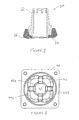
- a joystick controller has an operating shaft 10, which is mounted for pivotal movement relative to a body 12 (only part of which is shown) about a pivot centre X.
- the pivotal movement may be provided by means of a ball and socket arrangement or by other means such as gimbals mounted for pivotal movement about an axis.
- the joystick controller has a return-to-centre mechanism 11, which includes an annular bush or cone member 14 mounted so as to be able to slide up and down the operating shaft 10.
- An abutment 16 is fixed to the operating shaft 10 above the cone member 14.
- a helical compression spring 18 extends between the abutment 16 and an upward facing location surface 20 on the cone member 14.
- the body 12 includes an upper surface 22.
- the operating shaft extends through an opening 24 in the upper surface 22 such that the pivot centre X is below the opening and the return-to-centre mechanism 11 is above the opening.
- the cone member 14 has a lower surface 26, which abuts the upper surface 22 of the body 12. As can be seen in Figure 1B, when the operating shaft 10 is tilted relative to the body 12, the lower surface 26 of the cone member 14 is urged into contact with one side of the upper surface 22 of the body 12, and lifts away from the upper surface 22 at the other side. As a consequence, the cone member 14 slides up the operating shaft 10 and compresses the spring 18.
- the compression of the spring provides a resistive force that acts through the point of contact between the lower surface 26 of the cone member 14 and the upper surface 22 of the body 12.
- This resistive force is out of alignment with the pivot centre X and so provides a moment that acts against the force used (by the user's hand) to tilt the operating shaft 10.
- the moment acts to return the operating shaft to its central, or null position - the position shown in Figure 1B.
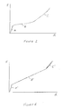
- Figure 2 is a graph showing the size of the resistive force F as a function of the angle of displacement ⁇ of the operating shaft 10.
- A the force required to commence movement of the operating shaft 10 from its central or null position. This is the force required to overcome static friction in the spring and pivot mechanisms.
- B the angle of displacement
- C the angle of displacement
- the increase in force is slight (B) for relatively small displacement angles but increases more rapidly (C) for larger angles.
- cone member 14 needs to be formed from a low-friction material so that it slides freely on the operating shaft 10.
- such materials seldom have good wear properties.
- the lower surface 26 of the cone member 14 can be subjected to large shear and compressive forces, which will tend to cause the cone material to wear. A significant amount of wear will alter the resistive force characteristics and upset the tactile feedback, especially if the wear to the lower surface 26 is greater on one side of the cone member 14 than on another side.
- Figure 3 shows a cone member 30 suitable for use in the joystick controller of the present invention.
- the cone member 30 includes an upper portion 32 of a material having a low coefficient of friction such that it slides freely on the operating shaft.
- the cone member 30 also includes a lower portion 34 fixed to the upper portion 32, and formed of a material having high resistance to shear and compressive forces.
- the lower portion 34 has much better wear resistance than the material of the upper portion 32.
- the lower portion 34 has a lower contact surface 36, of similar form to the lower contact surface 26 of Figures 1A and 1B.
- FIG 4 shows a cross-section through an upper body member 40 of a joystick controller.
- the upper body member 40 has a central gate opening 42 through which an operating shaft would extend in a similar manner to that described above with reference to Figures 1 and 2.
- the upper body member 40 also has a generally upwardly facing seat contact surface 44, which is the surface against which a cone member (such as the cone member 30 of Figure 3) is urged when the operating shaft is moved.
- the contact surface 44 has three regions: a flat inner region 44a, a mid-region 44b, which curves upwards with increasing distance from the centre, and an outer region 44c which has a steep upward slope.
- the three regions 44a, 44b, 44c are not annular in shape when viewed from above, but extend further in some directions than others (forming a "clover-leaf" shape as can be seen in Figure 5).
- the gate 42 has a square form with rounded corners.
- the rounded corners have a radius that corresponds to the radius of the operating shaft (not shown).
- This form provides the ability for the operating shaft of the joystick controller to be moved to any position within a square area.
- the square gate opening 42 allows for pivotal movement in two orthogonal directions (x and y) up to a maximum displacement in both the x and y directions simultaneously.
- the angle of displacement of the operating shaft i.e. the angle to the vertical, assuming the joystick is mounted to a horizontal surface
- the seat contact surface 44 is provided with a corresponding form that matches the square form of the gate opening 32.
- the seat contact surface is not square, but has rounded corners to account for the fact that the cone member (such as cone member 30), which contacts the seat contact surface 34 is of annular form, having a circular perimeter.
- the inner region 44a of the seat contact surface 44 provides a seat for the cone member when the operating shaft of the joystick is in the null position. However, as the operating shaft is moved away from the null position, the lower surface of the cone member that contacts the seat contact surface 44 does so in the mid- region 44b.
- the curved shape of the mid-region 44b is shaped to ensure that the resistive force increases linearly as the angle of displacement increases.
- the outer region 44c of the seat contact surface 44 presents a steeper surface against which the cone member is urged, and thereby a greater resistive force, when the joystick operating shaft is displaced close to its maximum angle of displacement. This feature provides an additional tactile feedback to the user and is termed an "over-press" facility. Only by providing a deliberate extra pressure on the operating shaft, will the user be able to move the operating shaft over the last few degrees before it reaches its maximum displacement.
Landscapes
- Physics & Mathematics (AREA)
- General Physics & Mathematics (AREA)
- Engineering & Computer Science (AREA)
- Automation & Control Theory (AREA)
- Mechanical Control Devices (AREA)
- Position Input By Displaying (AREA)
Applications Claiming Priority (1)
| Application Number | Priority Date | Filing Date | Title |
|---|---|---|---|
| GBGB0603925.9A GB0603925D0 (en) | 2006-02-28 | 2006-02-28 | Joystick controller |
Publications (1)
| Publication Number | Publication Date |
|---|---|
| EP1826652A1 true EP1826652A1 (fr) | 2007-08-29 |
Family
ID=36178874
Family Applications (1)
| Application Number | Title | Priority Date | Filing Date |
|---|---|---|---|
| EP07250756A Withdrawn EP1826652A1 (fr) | 2006-02-28 | 2007-02-22 | Commande de manette de jeu |
Country Status (3)
| Country | Link |
|---|---|
| US (1) | US20070268251A1 (fr) |
| EP (1) | EP1826652A1 (fr) |
| GB (1) | GB0603925D0 (fr) |
Families Citing this family (6)
| Publication number | Priority date | Publication date | Assignee | Title |
|---|---|---|---|---|
| JP4121730B2 (ja) * | 2001-01-19 | 2008-07-23 | 富士通コンポーネント株式会社 | ポインティングデバイス及び携帯型情報機器 |
| US8667413B2 (en) * | 2008-02-14 | 2014-03-04 | Creative Technology Ltd | Apparatus and method for information input in an electronic device with display |
| US20100302017A1 (en) * | 2009-06-01 | 2010-12-02 | Econtrols, Inc. | Tactile Feedback for Joystick Position/Speed Controls |
| US9568939B2 (en) | 2009-06-01 | 2017-02-14 | Enovation Controls, Llc | Tactile feedback for joystick position/speed controls |
| CN110189951B (zh) * | 2019-05-29 | 2024-05-07 | 德丰电创科技股份有限公司 | 一种操控杆 |
| US11921536B2 (en) * | 2022-01-26 | 2024-03-05 | Woodward, Inc. | Soft stop force gradient for control stick |
Citations (7)
| Publication number | Priority date | Publication date | Assignee | Title |
|---|---|---|---|---|
| US3115555A (en) * | 1961-01-30 | 1963-12-24 | Telemecanique Electrique | Hand lever switch |
| EP0043809A2 (fr) * | 1980-07-04 | 1982-01-13 | Hydrino Ab | Dispositif dans un levier multidirectionnel |
| FR2559305A1 (fr) * | 1984-02-08 | 1985-08-09 | Telemecanique Electrique | Manipulateur analogique |
| US5229742A (en) * | 1990-06-18 | 1993-07-20 | Kyocera Corporation | Joystick |
| GB2313175A (en) * | 1996-05-18 | 1997-11-19 | Penny & Giles Electronic Compo | A joystick controller |
| WO1999005060A1 (fr) * | 1997-07-25 | 1999-02-04 | Crown Equipment Corporation | Poignee de commande multifonction |
| DE19753867A1 (de) * | 1997-12-04 | 1999-06-10 | Linde Ag | Bedienhebel |
Family Cites Families (3)
| Publication number | Priority date | Publication date | Assignee | Title |
|---|---|---|---|---|
| SE443672B (sv) * | 1982-12-23 | 1986-03-03 | Akermans Verkstad Ab | Styrspakanordning |
| US5299742A (en) * | 1993-06-01 | 1994-04-05 | Anthony Manufacturing Corp. | Irrigation sprinkler nozzle |
| GB2341664B (en) * | 1996-05-18 | 2000-10-11 | Penny & Giles Controls Ltd | Electrical joystick controller |
-
2006
- 2006-02-28 GB GBGB0603925.9A patent/GB0603925D0/en not_active Ceased
-
2007
- 2007-02-22 EP EP07250756A patent/EP1826652A1/fr not_active Withdrawn
- 2007-02-26 US US11/711,262 patent/US20070268251A1/en not_active Abandoned
Patent Citations (7)
| Publication number | Priority date | Publication date | Assignee | Title |
|---|---|---|---|---|
| US3115555A (en) * | 1961-01-30 | 1963-12-24 | Telemecanique Electrique | Hand lever switch |
| EP0043809A2 (fr) * | 1980-07-04 | 1982-01-13 | Hydrino Ab | Dispositif dans un levier multidirectionnel |
| FR2559305A1 (fr) * | 1984-02-08 | 1985-08-09 | Telemecanique Electrique | Manipulateur analogique |
| US5229742A (en) * | 1990-06-18 | 1993-07-20 | Kyocera Corporation | Joystick |
| GB2313175A (en) * | 1996-05-18 | 1997-11-19 | Penny & Giles Electronic Compo | A joystick controller |
| WO1999005060A1 (fr) * | 1997-07-25 | 1999-02-04 | Crown Equipment Corporation | Poignee de commande multifonction |
| DE19753867A1 (de) * | 1997-12-04 | 1999-06-10 | Linde Ag | Bedienhebel |
Also Published As
| Publication number | Publication date |
|---|---|
| GB0603925D0 (en) | 2006-04-05 |
| US20070268251A1 (en) | 2007-11-22 |
Similar Documents
| Publication | Publication Date | Title |
|---|---|---|
| EP1826652A1 (fr) | Commande de manette de jeu | |
| CN211150382U (zh) | 键组件和具有该键组件的键盘 | |
| US6403898B2 (en) | Multiple switch assembly | |
| US20070164996A1 (en) | Joystick controller with centre-lock | |
| JP4553945B2 (ja) | 多方向スイッチ | |
| CN101390178B (zh) | 开关 | |
| US7781686B2 (en) | Operating element with a central pushbutton | |
| US10020137B2 (en) | Input apparatus | |
| US20080223703A1 (en) | Multifunctional operating element | |
| US10777373B2 (en) | Foot pedal for controlling a medical device | |
| US7129428B2 (en) | Joystick controller | |
| EP2126658A1 (fr) | Element de commande destine a un vehicule | |
| US11762412B2 (en) | Joystick device with haptic feedback | |
| CN108109871B (zh) | 限位开关 | |
| US20070000347A1 (en) | Kickdown mechanism for pedal assembly | |
| JP2012528423A (ja) | 角度のついたプランジャを有する電気スイッチアセンブリ | |
| US20190063592A1 (en) | Damping mechanism for a shift selector assembly and a shift selector assembly comprising the damping mechanism | |
| EP1801685B1 (fr) | Manette de commande avec des moyens de maintien en position | |
| US20240176382A1 (en) | Direction input device and controller | |
| EP4369156B1 (fr) | Dispositif d'entrée de direction et dispositif de commande | |
| JP2023525517A (ja) | 入力装置 | |
| US12164325B2 (en) | Multidirectional input device and controller | |
| US5190150A (en) | Ball bearing plunger actuator for a switch | |
| JPS6366808A (ja) | 押しボタンスイッチ | |
| EP1475816A1 (fr) | Interrupteur de commande |
Legal Events
| Date | Code | Title | Description |
|---|---|---|---|
| PUAI | Public reference made under article 153(3) epc to a published international application that has entered the european phase |
Free format text: ORIGINAL CODE: 0009012 |
|
| AK | Designated contracting states |
Kind code of ref document: A1 Designated state(s): AT BE BG CH CY CZ DE DK EE ES FI FR GB GR HU IE IS IT LI LT LU LV MC NL PL PT RO SE SI SK TR |
|
| AX | Request for extension of the european patent |
Extension state: AL BA HR MK YU |
|
| AKX | Designation fees paid | ||
| REG | Reference to a national code |
Ref country code: DE Ref legal event code: 8566 |
|
| STAA | Information on the status of an ep patent application or granted ep patent |
Free format text: STATUS: THE APPLICATION IS DEEMED TO BE WITHDRAWN |
|
| 18D | Application deemed to be withdrawn |
Effective date: 20080301 |