EP1827060A2 - Dispositif et système de refroidissement pour une torche à plasma d'arc et procédé associé - Google Patents
Dispositif et système de refroidissement pour une torche à plasma d'arc et procédé associé Download PDFInfo
- Publication number
- EP1827060A2 EP1827060A2 EP07103268A EP07103268A EP1827060A2 EP 1827060 A2 EP1827060 A2 EP 1827060A2 EP 07103268 A EP07103268 A EP 07103268A EP 07103268 A EP07103268 A EP 07103268A EP 1827060 A2 EP1827060 A2 EP 1827060A2
- Authority
- EP
- European Patent Office
- Prior art keywords
- power module
- fluid
- torch head
- cooling
- head portion
- Prior art date
- Legal status (The legal status is an assumption and is not a legal conclusion. Google has not performed a legal analysis and makes no representation as to the accuracy of the status listed.)
- Withdrawn
Links
Images


Classifications
-
- H—ELECTRICITY
- H05—ELECTRIC TECHNIQUES NOT OTHERWISE PROVIDED FOR
- H05H—PLASMA TECHNIQUE; PRODUCTION OF ACCELERATED ELECTRICALLY-CHARGED PARTICLES OR OF NEUTRONS; PRODUCTION OR ACCELERATION OF NEUTRAL MOLECULAR OR ATOMIC BEAMS
- H05H1/00—Generating plasma; Handling plasma
- H05H1/24—Generating plasma
- H05H1/26—Plasma torches
- H05H1/32—Plasma torches using an arc
-
- H—ELECTRICITY
- H05—ELECTRIC TECHNIQUES NOT OTHERWISE PROVIDED FOR
- H05H—PLASMA TECHNIQUE; PRODUCTION OF ACCELERATED ELECTRICALLY-CHARGED PARTICLES OR OF NEUTRONS; PRODUCTION OR ACCELERATION OF NEUTRAL MOLECULAR OR ATOMIC BEAMS
- H05H1/00—Generating plasma; Handling plasma
- H05H1/24—Generating plasma
- H05H1/26—Plasma torches
- H05H1/28—Cooling arrangements
-
- H—ELECTRICITY
- H05—ELECTRIC TECHNIQUES NOT OTHERWISE PROVIDED FOR
- H05H—PLASMA TECHNIQUE; PRODUCTION OF ACCELERATED ELECTRICALLY-CHARGED PARTICLES OR OF NEUTRONS; PRODUCTION OR ACCELERATION OF NEUTRAL MOLECULAR OR ATOMIC BEAMS
- H05H1/00—Generating plasma; Handling plasma
- H05H1/24—Generating plasma
- H05H1/26—Plasma torches
Definitions
- the present invention relates to a plasma arc torch and, more particularly, to a cooling device and system for a plasma arc torch and associated method.
- Such power supplies may include one or more power modules that generate the power required for torch operation.
- the power modules may be required to collectively provide from about 1-120 kilowatts (kW) or more of power for a torch.
- These power modules may be, for instance, IGBTs, SCRs or other suitable power modules.
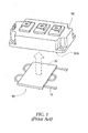
- One example of a typical power module 50 is shown in FIG. 1.
- one surface of the power module such as the bottom surface, may be configured to be flat and smooth so as to allow the surface to engage a heat sink device for removing excess heat from the power module.
- the heat sink device is a metal component provided with multiple fins to increase surface area of the heat sink device and thereby enhance convection of the heat away from the heat sink device.
- the heat sink device may be subjected to a stream of air blown across the fins to further enhance convection of the heat. In this manner, the goal is to limit the temperature of the power module during torch operation to an acceptable level.
- the heat sink device may comprise a discrete and closed liquid cooling plate as shown, for example, in FIG. 1.
- the cooling plate 10 includes a fluid circuit 15 for a liquid coolant encased within, for example, a metallic heat-conducting element 20 generally forming the overall structure of the cooling plate 10.
- the self-contained cooling plate 10 is engaged with a surface, such as the bottom surface, of the power module 50 to provide cooling therefor.
- Such a cooling plate 10 may also implement its own circulating cooling system (separate from the cooling system used to cool the torch head) including, for instance, a pump and a heat exchanger, for circulating a cooling fluid through the fluid circuit 15 to provide a medium for removing heat from the power module 50.
- the heat from the power module 50 must pass through the material of the heat conducting element 20, as well as the material of the fluid circuit 15, before reaching the liquid coolant.
- an interface material such as a gasket or thermal grease may be disposed between the heat-conducting element 20 and the power module 50 (as well as between the heat sink device and the power module in the above-described air-cooled heat sink), which may further increase the components through which the conducted heat must pass in order to reach the cooling fluid.
- these thermal conduction issues may limit the cooling efficiency of the cooling plate 10 in this application.
- the separate configurations (air-cooled heat sink or separate cooling plate) for cooling the power module(s) may tend to be inefficient or insufficient mechanisms for removing heat from the power module. Inefficient or insufficient removal of heat from the power module may cause a reduction in the power output thereof. In such cases, a larger power module, or additional power modules, may be required to provide sufficient power for operating the torch.
- the separate provisions (air-cooled heat sink or separate cooling plate) for cooling the power module(s) may, in some instances, result a bulkier or larger power supply for the torch (due to the extra components), a costlier power supply (and costlier system overall), possibly a less reliable power supply, or a more complex power supply.
- a plasma arc generation system comprising a power module operably engaged with a plasma arc torch head portion and adapted to provide an electrical current for causing an arc at the torch head portion for generating a plasma.
- a cooling device is operably engaged with the power module so as to direct a fluid thereto for cooling the power module.
- the cooling device is configured such that the fluid directly contacts the power module to receive heat therefrom generated by the power module.
- a plasma arc generation system comprising a plasma arc torch head portion adapted to receive an electrical current and configured such that the electrical current causes an arc at the torch head portion for generating a plasma.
- a power module is operably engaged with the torch head portion and is adapted to provide the electrical current thereto.
- a cooling device is operably engaged with the power module so as to direct a fluid thereto for cooling the power module. The cooling device is configured such that the fluid directly contacts the power module to receive heat therefrom generated by the power module.
- a further aspect of the present invention provides a method of cooling a plasma arc generation system.
- a fluid is directed to a power module, wherein the power module is operably engaged with a plasma arc torch head portion and is adapted to provide an electrical current thereto for causing an arc at the torch head portion for generating a plasma, such that the fluid directly contacts the power module to receive heat therefrom generated by the power module.
- the fluid is also directed to the torch head portion so as to receive heat therefrom generated by the plasma.
- the fluid is further directed one of serially between and in parallel to the power module and the torch head portion so as to provide cooling for the plasma arc generation system.
- embodiments of the present invention provide significant advantages as further detailed herein. More particularly, such embodiments provide a simpler and more efficient cooling system for the power module(s) of a torch power supply, with increased reliability and less cost, and results in a smaller or less bulky power supply.
- FIGS. 2-4 illustrate various embodiments of the cooling system 100 for cooling a power module 50 used, for example, to power a torch, generally represented by a torch head 200.
- a cooling system 100 may be applied to any torch implementing both a power module 50 and a fluid for cooling the torch head 200, wherein such a torch may be, for example, a water-cooled plasma arc torch.
- the torch head 200 shown in the Figures is merely exemplary of a representative torch having a plasma arc generation system implementing various forms of a cooling system 100 according to the present invention, and is not intended to be limiting in any manner.
- a representative torch includes a torch head 200 having a power module 50 electrically connected thereto, wherein such an electrical connection is represented by electrical or power lines 75A, 75B.
- a power module 50 and the electrical connections 75A, 75B may be necessary, for example, in a plasma arc torch, wherein the power module 50 and electrical connections 75A, 75B provide power to the torch head 200 for initiating and maintaining the plasma formed by the torch for cutting operations.
- a plasma torch and/or a plasma arc generation system or power supply therefor may also include a cooling system 100 for circulating a cooling fluid, such as, for example, water or a glycol solution, to the torch head 200 to provide cooling therefor.
- the cooling system 100 may comprise, for example, a circulating heat removal device 300 disposed remotely with respect to the torch head 200 and having a pump 400 for circulating the cooling fluid, a heat exchanger device or radiator 450 for dissipating heat received by the cooling fluid, and a tank or reservoir 350 for providing a particular capacity of the cooling fluid for the cooling system 100.
- the radiator 450 may be configured as a fluid-fluid heat exchanger or a fluid-air heat exchanger, as appropriate for the particular torch and/or plasma arc generation system.
- the cooling system 100 may also be configured to be in fluid communication with the torch head 200, as appropriate, through, for example, suitable tubing or hoses, or cooling passages defined by any or all of the components.
- each power module 50 may have been provided with a separate air-cooled finned heat sink, or separate liquid cooling device / system using a cooling plate 10 as shown in FIG. 1, in addition to the cooling system 100 for the torch head 200.
- such separate provisions for cooling the power module(s) 50 may have tended to be inefficient, thereby reducing the power output of the power module(s) 50 and/or may have caused additional power modules 50 to be required for providing sufficient power for operating the torch.
- the separate provisions for cooling the power module(s) 50 may have, in some instances, resulted in a bulkier or larger torch power supply (due to the extra components), a costlier torch power supply, possibly a less reliable torch power supply, and/or a more complex torch power supply.
- one embodiment of the present invention implements a cooling device 500 capable of being operably engaged with the power module(s) 50 of a plasma arc generation system and configured to cooperate with the circulating heat removal device 300 of the cooling system 100 used to cool the torch head 200, such that the cooling fluid circulated by the cooling system 100 is also used to cool the power module(s) 50.
- the cooling device 500 is configured to receive the cooling fluid in such a manner that the cooling fluid directly engages the power module 50 and receives the heat generated thereby.
- the cooling device 500 may be configured to cooperate with a surface of the power module 50, such as the interaction surface 50A, so as to define at least one channel 600 therebetween, wherein at least a portion of the channel 600 is define by the interaction surface 50A of the power module 50.
- the channel 600 includes a fluid inlet 750A and a fluid outlet 750B for receiving and discharging, respectively, the cooling fluid. The circulation of the cooling fluid through the cooling device 500 thus removes or dissipates the heat from the power module 50 as the cooling fluid passes through the radiator 450.
- the channel 600 defined by the cooling device 500 / power module 50 is arranged as a portion of the cooling system 100 for cooling the torch head 200. More particularly, the channel 600 may be disposed in series with the torch head 200 so that a separate cooling system for the cooling device 500 is not required. As shown in FIG. 2, the channel 600 may be disposed in series with and upstream of the torch head 200 such that the cooling fluid leaving the pump 400 first circulates through the channel 600 defined by the cooling device 500 / power module 50, before circulating to the torch head 200 and then back to the radiator 450 for dissipating the collected heat.
- Such a configuration may be advantageous in one aspect, since the power module 50 typically adds relatively less heat to the cooling fluid than the torch head 200, and thus the increase in temperature of the cooling fluid leaving the power module 50 is generally less than the temperature increase in the cooling fluid caused by the torch head 200. Accordingly, such a configuration may provide sufficient cooling of the power module 50, since the relatively cool cooling fluid first contacts the power module 50 before collecting heat from the torch head 200, but will still be capable of providing sufficient cooling for the torch head 200 due to the relatively small amount of heat collected from the power module 50.
- FIGS. 3 and 4 illustrate an embodiment wherein the flow direction of the cooling fluid is reversed as compared to the embodiment shown in FIG. 2. That is, the cooling fluid is directed by the pump 400 to the torch head 200. From the torch head 200, the cooling fluid is then serially directed to the cooling device 500 operably engaged with the power module(s) 50, whereafter, the cooling fluid leaving the power module(s) 50 is directed to the radiator 450 for dissipating the heat collected by the cooling fluid from the torch head 200 and the power module(s) 50. The cooling fluid, thus cooled, is then returned to the reservoir 350 for recirculation by the pump 400.
- Such a configuration may be advantageous, for example, where the most efficient operating temperature range of the power module 50 is above the temperature at which the cooling fluid leaves the circulating heat removal device 300. Accordingly, after the cooling fluid picks up the heat from the torch head 200, the cooling fluid may be adjusted to the desired temperature, for instance, with a supplemental radiator device (not shown) fluidly disposed between the torch head 200 and the power module 50, or by adjusting the flow rate of the cooling fluid (i.e., a faster flow collects relatively less heat), before the cooling fluid is directed to the power module 50.
- a supplemental radiator device not shown
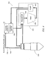
- FIG. 4 illustrates another embodiment wherein the cooling fluid is directed in parallel to the torch head 200 and the cooling device 500 operably engaged with the power module(s) 50, as compared to the embodiments showing a serial arrangement in FIGS. 2 and 3. That is, the cooling fluid is concurrently directed by the pump 400 to the torch head 200 and to the cooling device 500 operably engaged with the power module(s) 50 (the channel 600). The portions of the cooling fluid thus leaving the torch head 200 and the power module(s) 50, respectively, are then directed back to the radiator 450 for dissipating the heat collected by the cooling fluid from the torch head 200 and the power module(s) 50. That is, the cooling fluid directed to the torch head 200 does not circulate to the cooling device 500 (and vice versa) before returning to the radiator 450.
- the cooling fluid is then returned to the reservoir 350 for recirculation by the pump 400.
- both the power module 50 and the torch head 200 are exposed to a cooling fluid of the same temperature directed from the circulating heat removal device 300
- the implementation of a single circulating heat removal device 300 may also provide increased operating efficiency, may be simpler and require a fewer amount of components, and may provide a physically smaller power supply assembly.
- the cooling fluid flow through a series circulation configuration allows only one flow switch or other sensor device (not shown) to be engaged with the flow path of the cooling fluid so as to allow a clogged or plugged coolant channel to be detected anywhere in the plasma arc generation system.
- the flow switch or sensor may be configured, for example, to shut down the plasma arc generation system so as to prevent overheating.
- other sensor devices may be provided in the alternative or in addition to a flow switch or sensor in the cooling fluid flow path.
- the cooling device 500 may be provided with a thermal switch (i.e., as a failsafe) in case the cooling device 500 / circulating heat removal device 300 fail to maintain the power module 50 below a predetermined threshold temperature.
- a thermal switch i.e., as a failsafe
- references to such sensors herein are for exemplary purposes only and are not intended to be limiting in any manner.
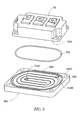
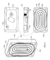
- FIGS. 5 and 6 illustrate various views of a cooling device 500 according to one embodiment of the present invention, wherein the cooling device 500 is configured to operably engage a power module 50 such that the cooling fluid circulated therethrough directly contacts or engages the power module 50 and thereby reduces, minimizes, or eliminates thermal interfaces between the power module 50 and the cooling fluid, to provide increased heat removal.
- the direct contact between the cooling fluid and the power module 50 provides increased cooling and may, in some circumstances, allow for a decreased number of power modules 50 required for the plasma arc generation system or power supply for a torch since each power module 50 may be able to handle more power if more efficiently and/or sufficiently cooled.
- the power module 50 includes an interaction surface 50A, which may be any surface thereof, smooth or not, through which heat generated by sources within the power module 50 can be directed to and conducted therethrough.
- an interaction surface 50A of a power module 50 may be a flat surface that, in some instances, may be referred to as a base or bottom plate.
- base or bottom plate is for exemplary purposes only and is not intended, in any manner, to connote an orientation, disposition, or configuration of the interaction surface 50A or the power module 50, or be otherwise restrictive in this regard in any manner. That is, the interaction surface 50A could be any or all of the side surfaces, the bottom surface, and the top surface of the power module 50.
- the cooling device 500 may be configured to engage the interaction surface 50A with a sealing member 700 disposed therebetween to provide a fluid-tight seal.
- a sealing member 700 may comprise, for example, a suitable o-ring or other gasket.
- the cooling device 500 may define a groove 700A for receiving at least a portion of the sealing member 700 for retaining the sealing member 700 in place as the cooling device 500 is engaged with the power module 50.
- the power module 50 may, in some instances, define a groove (not shown) for receiving at least a portion of the sealing member 700 in the alternative to, or in addition to, the groove 700A defined by the cooling device 500.
- a groove not shown
- many other sealing techniques between the power module 50 and the cooling device 500 may be employed, and that the configurations disclosed herein are for exemplary purposes only.
- the cooling device 500 may be secured to the power module 50 by an epoxy adhesive, or integrally formed with the power module 50.
- the cooling device 500 may comprise a block element 550 configured to define at least one channel 600 for directing the cooling fluid about the interaction surface 50A of the power module 50, where the block element 550 may be comprised of, for example, a metal such as aluminum.
- the at least one channel 600 is further configured such that, when the cooling device 500 is engaged with the power module(s), the interaction or engagement surface 50A of the respective power module 50 forms at least a portion of the at least one channel 600 such that the cooling fluid is capable of directly engaging the interaction surface 50A.
- the at least one channel 600 may alternatively be defined, for example, by the interaction surface 50A of the power module 50 (wherein the cooling device 500 may then comprise a flat plate), or by a combination of the cooling device 500 and the interaction surface 50A.
- the configurations described herein are for exemplary purpose only and are not intended to be limiting in any respect.
- the at least one channel 600 may be configured in the form of a spiral within the plane of the block element 550 and disposed radially inward of the groove 700A for receiving the o-ring 700 , and extending from a fluid inlet 750A to a fluid outlet 750B for receiving and discharging, respectively, the cooling fluid.
- the cooling fluid may be directed into "the fluid outlet 750B" and discharged from "the fluid inlet 750A" where necessary and/or desired.
Landscapes
- Physics & Mathematics (AREA)
- Engineering & Computer Science (AREA)
- Plasma & Fusion (AREA)
- Spectroscopy & Molecular Physics (AREA)
- Arc Welding Control (AREA)
- Plasma Technology (AREA)
- Arc Welding In General (AREA)
Applications Claiming Priority (1)
| Application Number | Priority Date | Filing Date | Title |
|---|---|---|---|
| US11/363,796 US7470872B2 (en) | 2006-02-28 | 2006-02-28 | Cooling device and system for a plasma arc torch and associated method |
Publications (2)
| Publication Number | Publication Date |
|---|---|
| EP1827060A2 true EP1827060A2 (fr) | 2007-08-29 |
| EP1827060A3 EP1827060A3 (fr) | 2011-05-04 |
Family
ID=38066571
Family Applications (1)
| Application Number | Title | Priority Date | Filing Date |
|---|---|---|---|
| EP07103268A Withdrawn EP1827060A3 (fr) | 2006-02-28 | 2007-02-28 | Dispositif et système de refroidissement pour une torche à plasma d'arc et procédé associé |
Country Status (5)
| Country | Link |
|---|---|
| US (1) | US7470872B2 (fr) |
| EP (1) | EP1827060A3 (fr) |
| JP (1) | JP4800987B2 (fr) |
| KR (1) | KR100888390B1 (fr) |
| CN (1) | CN101111120B (fr) |
Cited By (1)
| Publication number | Priority date | Publication date | Assignee | Title |
|---|---|---|---|---|
| CN109565921A (zh) * | 2016-08-11 | 2019-04-02 | 株式会社富士 | 等离子体产生装置及等离子体照射方法 |
Families Citing this family (8)
| Publication number | Priority date | Publication date | Assignee | Title |
|---|---|---|---|---|
| US20090241577A1 (en) * | 2008-03-26 | 2009-10-01 | Sanyo Electric Co., Ltd. | Chiller unit, refrigeration system having chiller unit and air conditioner having chiller unit |
| US8178814B2 (en) * | 2008-10-21 | 2012-05-15 | Perfect Point Edm Corp. | Hand-held electro-discharge device |
| CN205093032U (zh) * | 2012-10-18 | 2016-03-16 | 海别得公司 | 等离子电弧切割系统 |
| CA2956968A1 (fr) * | 2014-08-11 | 2016-02-18 | Best Theratronics Ltd. | Systeme et procede pour la separation d'isotope metallique par un processus de distillation thermique-sous vide combine |
| US11845149B2 (en) * | 2017-01-06 | 2023-12-19 | Lyco Manufacturing, Inc. | Power supply and method for dual process welding |
| US10897807B2 (en) * | 2018-09-21 | 2021-01-19 | The Esab Group Inc. | Power source cooling apparatus, method, and configuration |
| CN116390318B (zh) * | 2023-04-24 | 2024-06-18 | 中国科学院近代物理研究所 | 用于超高功率的ecr离子源的水冷微流道弧腔 |
| US12471260B2 (en) | 2023-05-23 | 2025-11-11 | The Esab Group, Inc. | IGBT temperature dampening systems and methods |
Family Cites Families (23)
| Publication number | Priority date | Publication date | Assignee | Title |
|---|---|---|---|---|
| JPS63154273A (ja) * | 1986-12-17 | 1988-06-27 | Mitsubishi Heavy Ind Ltd | プラズマト−チ |
| CA1310706C (fr) * | 1988-04-26 | 1992-11-24 | Toshihiko Okada | Appareil plasma a refroidissement par eau |
| JP2527746Y2 (ja) * | 1990-08-31 | 1997-03-05 | 株式会社ダイヘン | アーク加工用電源装置 |
| JPH05168238A (ja) * | 1991-12-17 | 1993-07-02 | Toshiba Corp | 水冷式半導体電力変換装置 |
| US5290995A (en) | 1991-12-20 | 1994-03-01 | Esab Welding Products, Inc. | Plasma arc cutting system having fluid metering and power control systems |
| JPH05318126A (ja) * | 1992-05-22 | 1993-12-03 | Daihen Corp | アーク溶接・切断トーチ用冷却水 |
| US5378870A (en) * | 1992-11-03 | 1995-01-03 | Krupnicki; Theodore A. | Power block for liquid-cooled power cables |
| JP2907746B2 (ja) * | 1995-01-31 | 1999-06-21 | 株式会社三社電機製作所 | 電源装置 |
| JPH1024368A (ja) * | 1996-07-09 | 1998-01-27 | Ishikawajima Harima Heavy Ind Co Ltd | 磁気攪拌溶接法およびその装置 |
| US5801442A (en) | 1996-07-22 | 1998-09-01 | Northrop Grumman Corporation | Microchannel cooling of high power semiconductor devices |
| JP2995005B2 (ja) | 1996-08-28 | 1999-12-27 | 核燃料サイクル開発機構 | 間接冷却方式プラズマジェットトーチ |
| US6400012B1 (en) | 1997-09-17 | 2002-06-04 | Advanced Energy Voorhees, Inc. | Heat sink for use in cooling an integrated circuit |
| JPH11120947A (ja) * | 1997-10-13 | 1999-04-30 | Ricoh Co Ltd | X線発生装置 |
| US6081423A (en) * | 1998-12-22 | 2000-06-27 | The Esab Group, Inc. | Power supply with obliquely impinging airflow |
| US6729383B1 (en) | 1999-12-16 | 2004-05-04 | The United States Of America As Represented By The Secretary Of The Navy | Fluid-cooled heat sink with turbulence-enhancing support pins |
| US6772040B1 (en) | 2000-04-10 | 2004-08-03 | Hypertherm, Inc. | Centralized control architecture for a plasma arc system |
| US20020117291A1 (en) | 2000-05-25 | 2002-08-29 | Kioan Cheon | Computer having cooling apparatus and heat exchanging device of the cooling apparatus |
| US6567262B2 (en) | 2001-06-01 | 2003-05-20 | Active Cool Ltd. | Liquid cooled TEC based system and method for cooling heat sensitive elements |
| JP3946018B2 (ja) | 2001-09-18 | 2007-07-18 | 株式会社日立製作所 | 液冷却式回路装置 |
| KR100604961B1 (ko) * | 2003-03-28 | 2006-07-26 | 홍영기 | 공기 플라즈마 토오치 |
| CA2474291C (fr) * | 2003-07-23 | 2010-01-12 | Illinois Tool Works Inc. | Methode et appareil pour refroidir de facon adaptative un systeme de soudage |
| US20050016978A1 (en) * | 2003-07-23 | 2005-01-27 | Stein Alan E. | Method and apparatus to adaptively cool a welding-type system |
| KR100526806B1 (ko) * | 2003-12-02 | 2005-11-08 | 기아자동차주식회사 | 자성유체를 이용한 마이크로 채널 방열 장치 |
-
2006
- 2006-02-28 US US11/363,796 patent/US7470872B2/en not_active Expired - Fee Related
-
2007
- 2007-02-26 KR KR1020070018923A patent/KR100888390B1/ko not_active Expired - Fee Related
- 2007-02-28 EP EP07103268A patent/EP1827060A3/fr not_active Withdrawn
- 2007-02-28 JP JP2007048206A patent/JP4800987B2/ja not_active Expired - Fee Related
- 2007-02-28 CN CN2007101288321A patent/CN101111120B/zh not_active Expired - Fee Related
Cited By (3)
| Publication number | Priority date | Publication date | Assignee | Title |
|---|---|---|---|---|
| CN109565921A (zh) * | 2016-08-11 | 2019-04-02 | 株式会社富士 | 等离子体产生装置及等离子体照射方法 |
| EP3500072A4 (fr) * | 2016-08-11 | 2020-03-18 | Fuji Corporation | Dispositif de génération de plasma et procédé d'irradiation de plasma |
| CN109565921B (zh) * | 2016-08-11 | 2021-05-18 | 株式会社富士 | 等离子体产生装置及等离子体照射方法 |
Also Published As
| Publication number | Publication date |
|---|---|
| CN101111120A (zh) | 2008-01-23 |
| US7470872B2 (en) | 2008-12-30 |
| EP1827060A3 (fr) | 2011-05-04 |
| US20070210039A1 (en) | 2007-09-13 |
| CN101111120B (zh) | 2012-08-08 |
| KR100888390B1 (ko) | 2009-03-13 |
| JP4800987B2 (ja) | 2011-10-26 |
| KR20070089607A (ko) | 2007-08-31 |
| JP2007229806A (ja) | 2007-09-13 |
Similar Documents
| Publication | Publication Date | Title |
|---|---|---|
| EP1827060A2 (fr) | Dispositif et système de refroidissement pour une torche à plasma d'arc et procédé associé | |
| KR102117141B1 (ko) | 열전-기반 열 관리 시스템 | |
| CN100334792C (zh) | 驱动装置 | |
| EP1538731B1 (fr) | Dispositif d'entrainement | |
| JP6157727B2 (ja) | モジュール型溶接機 | |
| CN114630558B (zh) | 一种散热系统、供电系统和充电桩 | |
| US20060243422A1 (en) | Liquid-cooled semiconductor unit for cooling high-power semiconductor elements that are enclosed in modules | |
| JP2020505900A (ja) | 半導体構成 | |
| WO2004025807A1 (fr) | Dispositif d'entrainement | |
| JP2008206345A (ja) | 電力変換装置 | |
| JP5712750B2 (ja) | 電力変換装置 | |
| CN216905720U (zh) | 一种冷却装置和电子设备 | |
| JP4075702B2 (ja) | 電力変換装置 | |
| CN103154685A (zh) | 冷却液用温度检测装置 | |
| CN114646235A (zh) | 热交换器,特别是用于电力电子设备的热交换器 | |
| CN112789957A (zh) | 带有单独的内部空间的变流器 | |
| JP6977505B2 (ja) | 電源装置 | |
| JP2007200915A (ja) | 冷却フィンおよび冷却装置 | |
| JP6177429B2 (ja) | 潜水艇の直流電圧変換器並びに燃料電池装置 | |
| JP4218664B2 (ja) | 電子部品冷却ユニット | |
| JP5158002B2 (ja) | 昇降圧コンバータ | |
| KR200235565Y1 (ko) | 고효율의 열전도성을 갖는 액체냉각방식의선형전력증폭기 유니트용 알루미늄 방열판 구조 | |
| US20240414897A1 (en) | Cooler, inverter and motor vehicle | |
| EP4726773A1 (fr) | Dispositif électronique de puissance à pompe intégrée | |
| JP6620247B2 (ja) | 車両用電力変換装置 |
Legal Events
| Date | Code | Title | Description |
|---|---|---|---|
| PUAI | Public reference made under article 153(3) epc to a published international application that has entered the european phase |
Free format text: ORIGINAL CODE: 0009012 |
|
| 17P | Request for examination filed |
Effective date: 20070228 |
|
| AK | Designated contracting states |
Kind code of ref document: A2 Designated state(s): AT BE BG CH CY CZ DE DK EE ES FI FR GB GR HU IE IS IT LI LT LU LV MC NL PL PT RO SE SI SK TR |
|
| AX | Request for extension of the european patent |
Extension state: AL BA HR MK YU |
|
| PUAL | Search report despatched |
Free format text: ORIGINAL CODE: 0009013 |
|
| AK | Designated contracting states |
Kind code of ref document: A3 Designated state(s): AT BE BG CH CY CZ DE DK EE ES FI FR GB GR HU IE IS IT LI LT LU LV MC NL PL PT RO SE SI SK TR |
|
| AX | Request for extension of the european patent |
Extension state: AL BA HR MK RS |
|
| AKX | Designation fees paid |
Designated state(s): AT BE BG CH CY CZ DE DK EE ES FI FR GB GR HU IE IS IT LI LT LU LV MC NL PL PT RO SE SI SK TR |
|
| STAA | Information on the status of an ep patent application or granted ep patent |
Free format text: STATUS: THE APPLICATION IS DEEMED TO BE WITHDRAWN |
|
| 18D | Application deemed to be withdrawn |
Effective date: 20150901 |