EP1828033B1 - Dispositif pour deriver de facon selective et dans le plan lateral des produits a partir d'un convoyeur - Google Patents
Dispositif pour deriver de facon selective et dans le plan lateral des produits a partir d'un convoyeur Download PDFInfo
- Publication number
- EP1828033B1 EP1828033B1 EP05825386A EP05825386A EP1828033B1 EP 1828033 B1 EP1828033 B1 EP 1828033B1 EP 05825386 A EP05825386 A EP 05825386A EP 05825386 A EP05825386 A EP 05825386A EP 1828033 B1 EP1828033 B1 EP 1828033B1
- Authority
- EP
- European Patent Office
- Prior art keywords
- diverter element
- diverter
- pivot axis
- conveyor
- transmission gear
- Prior art date
- Legal status (The legal status is an assumption and is not a legal conclusion. Google has not performed a legal analysis and makes no representation as to the accuracy of the status listed.)
- Expired - Lifetime
Links
Images




Classifications
-
- B—PERFORMING OPERATIONS; TRANSPORTING
- B65—CONVEYING; PACKING; STORING; HANDLING THIN OR FILAMENTARY MATERIAL
- B65G—TRANSPORT OR STORAGE DEVICES, e.g. CONVEYORS FOR LOADING OR TIPPING, SHOP CONVEYOR SYSTEMS OR PNEUMATIC TUBE CONVEYORS
- B65G47/00—Article or material-handling devices associated with conveyors; Methods employing such devices
- B65G47/74—Feeding, transfer, or discharging devices of particular kinds or types
- B65G47/76—Fixed or adjustable ploughs or transverse scrapers
- B65G47/766—Adjustable ploughs or transverse scrapers
-
- B—PERFORMING OPERATIONS; TRANSPORTING
- B65—CONVEYING; PACKING; STORING; HANDLING THIN OR FILAMENTARY MATERIAL
- B65G—TRANSPORT OR STORAGE DEVICES, e.g. CONVEYORS FOR LOADING OR TIPPING, SHOP CONVEYOR SYSTEMS OR PNEUMATIC TUBE CONVEYORS
- B65G2201/00—Indexing codes relating to handling devices, e.g. conveyors, characterised by the type of product or load being conveyed or handled
- B65G2201/02—Articles
- B65G2201/0264—Luggage
Definitions
- the present invention relates to a device for selectively diverting products sideways from a load-bearing conveying surface of a conveyor according to the preamble of claim 1.
- the guides In the active position, the guides form a blockade, as it were, for the products on the conveyor, forcing the products in the direction of the branch and preventing the products from remaining on the conveyor.
- pusher means which push the product in question sideways in the direction of the branch the moment said product passes.
- the guide When guides which are movable above the conveyor are used, it is known to provide these guides with vertically oriented endless guide belts functioning as a guide surface, which are driven in such a manner that the movement of the guide belts includes a component in the direction of movement of the conveyor.
- the guide In order to achieve that all products to be diverted, irrespective of their dimensions, are actually diverted from the conveyor in the direction of the branch, the guide preferably extends over the full width of the conveyor in the active position, so that products cannot pass the guide in the active position without being diverted in the direction of the branch.
- US patent US 6,607,065 B2 describes a device in which use is made of two guides that can pivot at ends remote from each other, about pivot axes located at two opposite longitudinal sides of the conveyor, between an active position, in which the guides are collineal and the guides jointly extend over the full width of the conveyor, and a passive position, in which the guides extend along the conveyor on opposite longitudinal sides thereof.
- the two guides are provided with vertical endless guide belts, which function as a moving guide surface for the products that are to be diverted from the conveyor.
- a drawback is the fact that because of the use of two guides and the required transmissions therebetween, the device is highly complex and, in addition, takes up space on both longitudinal sides of the conveyor as well as on the bottom side thereof. Moreover, the use of two opposite guides involves the risk of products finding their way between the ends of the guides, so that the products cannot be discharged sideways as intended and/or are damaged.
- a device as referred to in the introduction is known from US patent US 3,104,755 .
- Said document discloses a roller conveyor comprising a branch that extends transversely thereto. Products can be supplied in the direction of branch on the roller conveyor from two opposite sides of the roller conveyor.
- a device provided with two mirror-symmetrical guides is disposed, whose guide surfaces are made up of vertically oriented guide belts, which are each passed over three pulleys.
- the ends of the guides are coupled via a gear transmission, in such a manner that in a passive position the guide surfaces of the two guides are disposed in collinear relationship beside the roller conveyor, whilst in the active position of the guides the guide surfaces define a V-shape above the roller conveyor, each guide defining one leg of the V-shape, with the point of the V-shape extending above the roller conveyor and the two guides being pivoted in opposite directions about pivot axes located beside the roller conveyor.
- the device is provided with a pneumatic reciprocating cylinder, which pivots a shaft member which is co-axial with the pivot axis of one of the two guides and which is rigidly connected to the guide in question, so that not only the shaft member but also the associated guide is pivoted.
- the guide on which the pneumatic cylinder does not act directly is provided with a driving motor for driving the guide belt thereof, which drive unit is connected to the guide belt of the other guide via the gear transmission at the ends of the guides that extend above the roller conveyor in the active position, so that the guide belts of the other guide are driven as well, albeit in opposite direction.
- the object of the present invention is to provide a device as referred to in the introduction which extends only on one side of the conveyor, at least in the passive position, and which has a limited overall length on the side in question.
- a device according to claim 1 is provided.
- said first further vertical pivot axis is located on the same side of the conveyor as the vertical pivot axis, and/or the diverter element pivots In the opposite direction between the passive position and the active position when the actuating element pivots between the first position at the second position.
- the entire actuating element preferably extends between the ends of the diverter element, seen In the direction of transport.
- the actuating element is preferably at least substantially elongated and/or rectilinear in shape.
- the actuating element is preferably made up of a rigid arm for the sake of constructional simplicity.
- the actuating element is made up of an extensible arm, so that in particular said increasing or decreasing of the distance between the pivot axis and one end of the diverter element can be effected in a simple manner.
- the engagement by the actuating element on the movable part of the diverter element takes place on a side of the movable part of the diverter element that faces towards the pivot axis.
- the guide belt it is preferably an endless belt.
- the guide belt is passed at least over a third pulley which is rotatable about a vertical axis of rotation and which is movable between a starting position and an end position for keeping the length of the path along which the guide belt moves at least substantially constant during said increasing or decreasing of the distance between the pivot axis and one end of the diverter element.
- the third pulley can move reciprocatingly beside the conveying surface between the starting position and the end position.
- the third pulley need not form part of the diverter element, so that this third pulley will not affect the mass inertia effects caused by the pivoting of the diverter element between the active position and the passive position.
- the handling capacity is to a significant extent determined by the time involved in said pivoting of the diverter element from the passive position to the active position and vice versa, since said time is also indicative of the minimum spacing that needs to be maintained between two successive products on the conveyor. The quicker the diverter element can pivot to and fro, the smaller the required spacing between the products and/or the higher the conveyor velocity to be used.
- a device for selectively diverting products sideways from a load-bearing surface of a conveyor, comprising a diverter element provided with a guide belt that can be driven by drive means, which belt is passed over two pulleys at ends of the diverter element, which pulleys are rotatable about vertical axes of rotation, one of which two pulleys is rotatable with respect to a base part of the diverter element and the other of which two pulleys is rotatable with respect to a part of the diverter element that is movable with respect to the base part, pivoting means for pivoting the diverter element reciprocatingly about a vertical pivot axis extending on one side of the conveyor, between a passive position, in which the diverter element extends beside the conveying surface so as to allow products on the conveying surface to pass freely, and an active position, in which the diverter element extends at
- the device furthermore comprises mechanical transmission means for moving the third pulley between the starting position and the end position in response to the increase or decrease of the distance between the pivot axis and one end of the diverter element. In this way no separate drive means are required for moving the third pulley.
- a preferred embodiment that is constructionally advantageous because of its simplicity is characterized in that the transmission means comprise a first transmission gear, a first transmission element, a second transmission gear and a second transmission element, wherein the first transmission element is connected to the movable part of the diverter element on the one hand and co-operates with the first transmission gear on the other hand, the second transmission element is connected to the third pulley on the one hand and to the second transmission gear on the other hand, and wherein the first transmission gear and the second transmission gear are arranged for joint rotation.
- the first and/or the second transmission gear may be configured as gear wheels, for example.
- first transmission gear and the second transmission gear can be realised in an advantageous manner if the first transmission gear and the second transmission gear are collinear, in which case the first transmission gear and the second transmission gear are furthermore preferably made up of one common transmission gear.
- first transmission element and the second transmission element engage different parts of the common transmission gear.
- At least one of said first transmission gear and said second transmission gear is collinear with the pivot axis. This achieves that said at least one transmission element that is collinear with the pivot axis will not move with respect to the diverter element upon pivoting of the diverter element.
- At least one of said first transmission element and said second transmission element is of an elongated, flexible, preferably endless type.
- the movable part and the base part each comprise two pulleys.
- the length of the path along which the guide belt extends can be kept constant in a simple manner in spite of the movement of the movable parts of the diverter element with respect to the base part.
- the two pulleys of the base part and/or of the movable part are preferably positioned at fixed positions relative to each other for reasons of constructional simplicity.
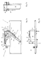
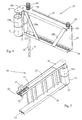
- the diverter element 6 comprises a fixed arm 10 ( figure 4 ) and an arm 11 ( figure 5 ) that is movable with respect to the fixed arm 10 in the longitudinal direction thereof.
- the fixed arm 10 comprises an elongated C-shaped section 15. To increase the stiffness of the section 15, the free ends of the V-shape are connected at space-apart locations via obliquely oriented connecting strips 29a, 29b.
- the horizontal parts thereof are provided with guide strips 18, 19. Beside the centre of the width thereof, a narrow slots 35 is provided in the upper horizontal part of the C-shape, parallel to the guide strip 18.
- a shaft member 34 extends through the two horizontal parts of the C-shape of the section 15, in such a manner that the fixed arm 10 can freely pivot about the shaft member 34, whose central axis coincides with the aforesaid pivot axis 9.
- gears 23, 24 and 25 are provided at the ends of the slots 35.
- the gears 23 and 24 are mounted on the shaft member 34 above the C-shaped section 15 in such a manner as to be freely rotatable. Consequently, the central axis of the gears 23, 24 coincides with the pivot axis 9.
- the gears 23 and 24 might also be configured as a common gear having a height corresponding to the joint height of the gears 23 and 24.
- the gear 25 is mounted on the upper horizontal part of the C-shaped section 15 in such a manner as to be freely rotatable, with the gears 23 and 25 extending at the same vertical level.
- the fixed arm 10 is provided with a pulley 12 that is rotatable about an axis of rotation 12a.
- the fixed arm 10 is furthermore provided with parts 16, 17 extending perpendicularly to the longitudinal direction of the fixed arm 10, between which parts a pulley 13 that is rotatable about an axis of rotation 13a is provided.
- the movable arm 11 comprises two U-shaped sections 26, 27, the open sides of the U-shapes of which sections 26, 27 are directed downwards and upwards, respectively.
- the sections are interconnected via a vertical connecting beams 28a, 28b, 28c, which are also U-shaped.
- the U-shaped sections 26, 27 are provided at the inner side thereof with sliding shoes 20, 21 and a sliding shoe 22, respectively (the second sliding shoe, which is associated with section 26 and which corresponds to the sliding shoe 21 associated with section 27, is not shown).
- the sliding shoes 20, 21 are arranged to cooperate with the guide strip 18, whilst the guide shoe 22 is arranged to cooperate with the guide strip 19.
- the section 27 is provided with a mounting plate 33 between the guide shoes 20, 21 and a vertical upright side of the U-shape of the section 27, which mounting plate extends through the slot 35 of the fixed arm 10 in the assembled condition of the diverter element 6, being movable therethrough upon movement of the movable arm 11 with respect to the fixed arm 10.
- the section 27 is furthermore provided at the bottom side thereof with a downwardly extending shaft hub 32. During the sliding cooperation between the fixed arm 10 and the movable arm 11, the hub 32 is positioned between the connecting strips 29a, 29b.
- the sections 26, 27 are provided with extension strips 36, 37 attached thereto, between the free ends of which the pulley 14 is mounted in such a manner as to be freely rotatable about the axis of rotation 14a.
- the diverting device 5 comprises a table 8, on which several components of the diverting device 5 are movably or immovably mounted.
- a pulley 38 is provided on the table 8, which pulley is rotatable about a vertical axis of rotation 38a and which has the same height as the pulleys 12, 13, 14.
- the pulley 38 is rotatably driven by an electric motor (not shown) at the bottom side of the table 8.
- the table 8 is provided with a slot 39 and, parallel thereto, with a guide strip 40 along which a slide 41 can move reciprocatingly.
- the slide 41 comprises a pulley 42, which is freely rotatable about a vertical axis of rotation 42a.
- the diverting device 5 furthermore comprises two gears 43, 44 that extend above the slide 41, viz. at the same vertical level as the gear 24.
- a toothed belt 45 is passed over the gears 24, 43, 44 in such a manner as to extend in the form of a triangle.
- the toothed belt 45 is fixedly connected to the slide 41 via a corner joint 46.
- a toothed belt 47 is passed over the gears 23, 25, which belt is fixedly connected to the mounting plate 33, and thus to the movable arm 11, by means of a mounting plate 48.
- the diverting device 5 furthermore comprises an actuator arm 49, which is freely rotatably connected to the hub 32 at one end.
- the arm 49 is rigidly connected to a vertical shaft member 50, which is in turn connected at the bottom side of the table 8 to a crank-drive shaft mechanism 51 (see figures 2a and 2b ), which is driven by an electric motor 52.
- the diverting device 5 furthermore comprises a vertically oriented guide belt 30, which is passed over the pulleys 12, 13, 14, 38, 42.
- the guide belt 30 is driven via the drive of the pulley 38 in the direction indicated by the arrow 53, i.e. in the direction in which the guide element 6 discharges products from the conveyor belt 4 in the active position, with a component in the direction of transport 7.
- said component is of the same magnitude as the conveying velocity of the belt conveyor 1.
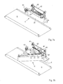
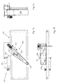
- the diverting device 5 operates as follows: starting from the passive position of the diverter element 6, in which products present on the conveyor belt 4 can pass the diverging device 5 without impediment, the electric motor 52 receives an activating signal from control means (not shown) at some point triggered by the fact that a product on the conveyor belt 4 that is to be diverted sideways from the conveyor belt 4 is approaching the diverging device 5. In response thereto, the electric motor 52 is energised, as a result of which the actuator arm 49 is pivoted via the crank-drive shaft mechanism 51 and the shaft member 50 from the position that is shown in figure 1a , for example, to the position that is shown in figure 2a .
- the diverter element 6 Because of the engagement of the actuator arm 49 on the movable arm 11 of the diverter element 6, the diverter element 6 will pivot as a whole from the passive position as shown in figure 1a to the active position as shown in figure 2a , whilst in addition the movable part 11 of the fixed arm 10 moves away from the diverter element 6 in the longitudinal direction thereof, causing the distance between the pivot axis 9 for the diverter element 6 and the pulley 14 to increase.
- the length along which the diverter element 6 extends as a result thereof suffices to cover the full width of the conveyor belt 4, which would not be possible with the length that the diverter element 6 takes up in the passive position.
- the length of the path along which the guide belt 30 extends past the five pulleys 14, 38, 42, 30, 12 remains constant, so that it is ensured that the belt 30 will continue to be driven via the pulley 38.
- the driving motor 52 causes the actuator arm 49 to pivot via the crank-drive shaft mechanism 51 from the position that is shown in figure 2a back to the position that is shown in figure 1a , with the movable arm 11 being moved back into the fixed arm 10 of the diverter element 6 on the one hand and the diverter element 6 as a whole pivoting back to the passive position that is shown in figure 1 a. Because of the transmission between the toothed belts 45 and 47 via the gears 23, 24, the slide 41 will furthermore return to the starting position again, so that the situation as shown in figure 1 a applies again.
- Figures 6a-10 relate to a second preferred embodiment of a device according to the present invention.
- Figures 6a-6c and figure 8a show the device in the passive position thereof, whilst figures 7a-7c and figure 8b show the device in the active position thereof.
- the device comprises a belt conveyor 101 and the diverging device 105.
- the belt conveyor 101 is comparable to the belt conveyor 1 and requires no further explanation.
- the diverging device 105 comprises the diverter element 106, which is pivotable about a pivot axis 109 between the passive position and the active position.
- the diverter element 106 comprises a fixed arm 110 (see figure 9 ) and an arm 111 ( figure 10 ) which is movable with respect to the fixed arm 110.
- the fixed arm 110 comprises a laterally oriented U-shaped section 115 having an upper horizontal part 161, a lower horizontal part 162 and a vertical part 163 that interconnects the two horizontal parts 161, 162.
- Pulleys 112, 113 are provided at both ends of the U-shaped section 115, which pulleys are rotatable about axes of rotation 112a, 113a, respectively.
- a shaft member 164 extends above the horizontal part 161, which shaft member is rigidly connected to the pulley 112.
- Mounted on the horizontal part 161 is an electric motor 155 comprising a transmission 166 for rotating the pulley 112 via the shaft member 164.
- Guide strips 118, 119 are mounted to the vertical part 163 on the inner side of the U-shaped section 115, which guide strips extend in slightly spaced-apart parallel relationship in the longitudinal direction of the U-shaped section 115.
- a shaft member 134 whose central axis coincides with the aforementioned pivot axis 109, extends through the horizontal parts 161, 162 of the U-shaped section 115 near the pulley 112.
- the shaft member 134 is rigidly connected to the U-shaped section 115 and extends below the lower horizontal part 162 to a significant extent, so that the journalling of the shaft member 134 for rotation of the diverter element 106 about the pivot pin 109 can take place below the horizontal part 162.
- the movable arm 111 ( figure 10 ) comprises a section 157 of substantially C-shaped cross-section, which cross sectional configuration is not entirely constant along the length of the section 167.
- the section 167 is substantially made up of an upper horizontal part 168 and a lower horizontal part 169, which are interconnected via a vertical part 170.
- the horizontal parts 168, 169 are wider on the sides of the section 157 that face towards the fixed arm 110, thus forming projecting parts 116, 117, between which the pulley 114 is freely rotatable about a vertical axis of rotation 114a.
- the vertical part 170 is provided with two recessed parts 171, 172.
- guide shoes 120, 121 are provided within the recessed parts 171, 172 for guiding cooperation with the guide strips 118, 119, respectively.
- a vertical hub 132 is rigidly attached to the upper side of the horizontal part 168.
- Recessed parts 173, 174 collinear with the recessed parts 171, 172 are provided along the part of the length of the section 167 where no recessed parts 171, 172 are present, which recessed parts 173, 174 are narrower than the recessed parts 171, 172 and which are intended to provide space for the guide strips 118, 119.
- extension strips 136, 137 are provided on the horizontal parts 168, 169, between which the pulley 142 is freely rotatable about the vertical axis of rotation 142a.
- the horizontal parts 161, 162 of the fixed arm 110 extend at the outer side of the respective horizontal parts 168, 169 of the movable arm 111.
- the diverter element 106 furthermore comprises an endless guide belt 130, which is passed over the pulleys 112, 113, 114, 142 and which is driven in the direction indicated by the arrow 153 by the action of the electric motor 165.
- the diverter element 106 furthermore comprises an actuator arm 149, which is rotatably connected at one end to the shaft hub 132 and which is rigidly connected at the opposite end to the shaft member 150, which is in turn connected at the bottom side of the table 108 to a crank-drive shaft mechanism 151 that is driven by the electric motor 152.
- the operation of the device is as follows: once a control system (not shown) has determined that a product that is approaching the diverter element on the belt conveyor 101 is to be diverted sideways therefrom, the diverter element 106 must be moved from the passive position to the active position.
- the electric motor 152 is to that end energised, with the outgoing shaft of said electric motor rotating half a revolution, causing the actuator arm 149 to pivot through about 45° about the central axis of the shaft member 150.
- the result is that on the one hand the movable arm 111 moves outwards with respect to the fixed arm 110, whilst on the other hand the diverter element 106 as a whole pivots about the pivot axis 109.
- the electric motor can rotate a next half revolution, causing the diverter element 106 to pivot back to the passive position, whilst in addition the diverter element assumes its original length again. Suitable timing makes it possible to achieve that the electric motor 152, after having rotated the first half revolution, will not stop once the diverter element 106 has reached the active position but will immediately proceed with the second half revolution, so that the diverter element 108, too, will immediately pivot back to the passive position again without stopping.
- FIGS 11-13 schematically show three embodiments of a device not forming part of the present invention. All the figures show a conveyor 201 for conveying products thereon in the direction indicated by the arrow 202. Each of the figures 11-13 shows the diverter element both in the passive position and downstream in the active position; in the active position the same numerals are used as in the passive position, with the addition of an apostrophe, however.
- the diverter element 301 comprises pulleys 302, 303, 304, 305, with the pulleys 302 and 303 forming part of a base part of the diverter element 301 and the pulleys 304 and 305 forming part of a part of the diverter element that is movable with respect to the base part.
- a guide belt 306 is passed over the pulleys 302, 303, 304, 305, which guide belt is driven via the drive of one of the pulleys, of which the pulleys 302 and 303 are most likely to be used for this purpose.
- the directly drivable, active piston-cylinder combination 307 the distance between the pulleys 302 and 305 can be changed by moving the movable arm with respect to the fixed arm of the diverter element 301.
- pivot axis 308 for the diverter element 301 coincides with the central axis of the pulley 302.
- pivoting of the diverter element 301 about the central axis of the pulley 302 does not take place by means of an active actuator arm (which would also be possible), but by means of a drive unit which acts directly on the shaft that extends through the central axis of the pulley 302, to which shaft the diverter element 301 is rigidly connected.
- the diverter element 401 that is shown in figure 12 comprises three pulleys 402, 403, 404, of which pulleys the pulleys 402, 403 form part of a fixed arm of the diverter element 401, whilst the pulley 404 forms part of an arm of the diverter element 401 that is movable with respect to the fixed arm.
- a fixed pulley 405 is provided, which is comparable to the pulley 38 that is used in the first preferred embodiment, and the pulley 406, which forms part of a slide and which can move reciprocatingly in a manner that is comparable to the manner In which the pulley 42 that is used In the first preferred embodiment reciprocates.
- a guide belt 408 is passed over the five pulleys 402, 403, 404, 405, 406. Pivoting of the diverter element 401 about the central axis of the pulley 402 takes place in a manner which is comparable to the pivoting in the embodiment that is shown in figure 11 , viz. via a driven shaft that extends concentrically with the central axis of the pulley 402.
- a difference between the embodiment of figure 12 and the first preferred embodiment of figures 1a-5 is the fact that the pivot axis 407 for the diverter element 401 coincides with the central axis of the pulley 402.
- a difference with the embodiment of figure 11 Is the piston-cylinder combination 410 which, in contrast to the piston-cylinder combination 307, is passive by nature. Extension of the piston of the piston-cylinder combination 410 takes place by means of the arm 409, which arm moves along and is connected to an end of the piston of the piston-cylinder combination 410 at one end and which can rotate about a vertical axis at another end, at the location indicated by numeral 411. Pivoting of the diverter element 401 causes the arm 401 to pivot as well, as a result of which the piston-cylinder combination 410 and thus the pulley 404 is extended.
- the fixed arm of the diverter element 501 comprises only one pulley 502, in contrast to the embodiment of figure 12 , the central axis of which pulley 502 coincides with the pivot axis for the diverter element 501.
- the pulleys 604, 605 and 506 are absolutely comparable to the pulleys 404, 405 and 406 in figure 12 .
- the piston-cylinder combination 508 is in the active position.
Landscapes
- Engineering & Computer Science (AREA)
- Mechanical Engineering (AREA)
- Branching, Merging, And Special Transfer Between Conveyors (AREA)
- Intermediate Stations On Conveyors (AREA)
Claims (21)
- Dispositif pour faire dévier de façon sélective et dans le plan latéral des produits à partir d'une surface d'acheminement porteuse de charge (4) d'un convoyeur (1 ; 101; 201), comprenant un élément de déviation (6 ; 106) pourvu d'une courroie de guidage (30 ; 130) qui peut être entraînée par un moyen d'entraînement (165), la courroie passant sur deux poulies (14, 12 ; 142, 112) à des extrémités de l'élément de déviation, les poulies étant rotatives autour d'axes de rotation verticaux, l'une des deux poulies (12 ; 112) étant rotative par rapport à une partie de base (10 ; 110) de l'élément de déviation et l'autre des deux poulies (14 ; 142) étant rotative par rapport à une partie (11 ; 111) de l'élément de déviation qui est mobile par rapport à la partie de base dans sa direction longitudinale, un moyen de pivotement (52 ; 152) pour faire pivoter l'élément de déviation en va-et-vient autour d'un axe de pivot vertical (9 ; 109) s'étendant sur un côté du convoyeur, entre une position passive dans laquelle l'élément de déviation s'étend à côté de la surface d'acheminement de façon à permettre aux produits sur la surface d'acheminement de passer librement, et une position active dans laquelle l'élément de déviation s'étend au moins partiellement au-dessus de la surface d'acheminement pour faire dévier dans le plan latéral des produits sur la surface d'acheminement à partir de ladite surface d'acheminement, et un moyen de réglage de longueur (18-22 ; 118-121) pour augmenter la distance entre l'axe de pivot et une extrémité de l'élément de déviation lors du pivotement de la position passive à la position active et pour réduire la distance entre l'axe de pivot et l'extrémité de l'élément de déviation lors du pivotement de la position active à la position passive, où la partie mobile de l'élément de déviation se déplace par rapport à la partie de base de l'élément de déviation de manière à augmenter ou réduire la distance entre l'axe de pivot et l'extrémité de l'élément de déviation, où le dispositif comprend un élément d'actionnement (49 ; 149) qui met en prise l'élément de déviation, l'élément d'actionnement pouvant être déplacé entre une première position et une seconde position par un moyen de déplacement (52 ; 152) de manière à faire pivoter l'élément de déviation entre la position passive et la position active sous l'influence du déplacement de l'élément d'actionnement entre la première position et la seconde position, et/ou à augmenter ou réduire la distance entre l'axe de pivot et l'extrémité de l'élément de déviation, où l'élément d'actionnement (49 ; 149) peut pivoter autour d'un premier axe de pivot vertical supplémentaire (50 ; 150) entre ladite première position et ladite seconde position, caractérisé en ce que ledit élément d'actionnement met en prise la partie mobile de l'élément de déviation et en ce que ledit premier axe de pivot vertical supplémentaire est situé entre les extrémités de l'élément de déviation, vu dans la direction de transport du convoyeur.
- Dispositif selon la revendication 1, caractérisé en ce que ledit premier axe de pivot vertical supplémentaire est situé du même côté du convoyeur que l'axe de pivot vertical.
- Dispositif selon la revendication 2, caractérisé en ce que l'élément de déviation (6 ; 106) pivote dans la direction opposée entre la position passive et la position active lorsque l'élément d'actionnement (49 ; 149) pivote entre la première position et la seconde position.
- Dispositif selon l'une quelconque des revendications précédentes, caractérisé en ce que l'élément d'actionnement (49 ; 149) dans son ensemble s'étend entre les extrémités de l'élément de déviation, vu dans la direction de transport.
- Dispositif selon l'une quelconque des revendications précédentes, caractérisé en ce que l'élément d'actionnement (49 ; 149) est de forme au moins sensiblement allongée.
- Dispositif selon l'une quelconque des revendications précédentes, caractérisé en ce que l'élément d'actionnement (49 ; 149) est de forme au moins sensiblement rectiligne.
- Dispositif selon l'une quelconque des revendications précédentes, caractérisé en ce que l'élément d'actionnement est constitué d'un bras rigide (49 ; 149).
- Dispositif selon l'une quelconque des revendications précédentes, caractérisé en ce que la mise en prise par l'élément d'actionnement (49 ; 149) sur la partie mobile (11 ; 111) de l'élément de déviation (6 ; 106) a lieu d'un côté de la partie mobile de l'élément de déviation tourné vers l'axe de pivot (9 ; 109).
- Dispositif selon l'une quelconque des revendications précédentes, caractérisé en ce que la courroie de guidage (30 ; 130) est une courroie sans fin.
- Dispositif selon l'une quelconque des revendications précédentes, caractérisé en ce que la courroie de guidage (30 ; 130) passe au moins sur une troisième poulie (42 ; 114) qui est rotative autour d'un axe de rotation vertical et qui est mobile entre une position de départ et une position de fin pour maintenir la longueur du trajet le long duquel se déplace la courroie de guidage sensiblement constante pendant ladite augmentation ou réduction de la distance entre l'axe de pivot et une extrémité de l'élément de déviation (6 ; 106).
- Dispositif selon la revendication 10, caractérisé en ce que la troisième poulie (42) peut se déplacer en va-et-vient à côté de la surface d'acheminement (4) entre la position de départ et la position de fin.
- Dispositif selon la revendication 10 ou 11, caractérisé en ce que le dispositif comprend en outre un moyen de transmission mécanique (40 ; 41) pour déplacer la troisième poulie (42) entre la position de départ et la position de fin en réponse à l'augmentation ou la réduction de la distance entre l'axe de pivot et une extrémité de l'élément de déviation.
- Dispositif selon la revendication 12, caractérisé en ce que le moyen de transmission comprend un premier engrenage de transmission (23), un premier élément de transmission (47), un second engrenage de transmission (24) et un second élément de transmission (45), où le premier élément de transmission est raccordé à la partie mobile (11) de l'élément de déviation d'une part et coopère avec le premier engrenage de transmission d'autre part, le second élément de transmission est raccordé à la troisième poulie (42) d'une part et au second engrenage de transmission d'autre part, et où le premier engrenage de transmission et le second engrenage de transmission sont agencés pour une rotation conjointe.
- Dispositif selon la revendication 13, caractérisé en ce que le premier engrenage de transmission (23) et le second engrenage de transmission (24) sont colinéaires.
- Dispositif selon la revendication 14, caractérisé en ce que le premier engrenage de transmission (23) et le second engrenage de transmission (24) sont constitués d'un engrenage de transmission commun.
- Dispositif selon la revendication 13, 14 ou 15, caractérisé en ce qu'au moins un dudit premier engrenage de transmission (23) et dudit second engrenage de transmission (24) est colinéaire avec l'axe de pivot (9).
- Dispositif selon l'une quelconque des revendications 13 à 16, caractérisé en ce qu'au moins l'un dudit premier élément de transmission (47) et dudit second élément de transmission (45) est de type flexible et allongé.
- Dispositif selon la revendication 17, caractérisé en ce que ledit au moins un élément de transmission flexible et allongé est un élément sans fin.
- Dispositif selon l'une quelconque des revendications précédentes, caractérisé en ce que la partie mobile (111) et la partie de base (110) comprennent chacune deux poulies (114, 142 ; 112, 113).
- Dispositif selon la revendication 19, caractérisé en ce que les deux poulies (114, 142 ; 112, 113) de la partie de base (110) et/ou de la partie mobile (111) sont positionnées à des positions fixes l'une par rapport à l'autre.
- Dispositif selon l'une quelconque des revendications précédentes, caractérisé en ce que l'élément de déviation (6 ; 106) s'étend sur toute la largeur du convoyeur dans la position active.
Applications Claiming Priority (2)
| Application Number | Priority Date | Filing Date | Title |
|---|---|---|---|
| NL1027879A NL1027879C2 (nl) | 2004-12-24 | 2004-12-24 | Inrichting voor het selectief zijwaarts van een transporteur af geleiden van producten. |
| PCT/NL2005/000875 WO2006068470A1 (fr) | 2004-12-24 | 2005-12-20 | Dispositif pour deriver de facon selective et dans le plan lateral des produits a partir d'un convoyeur |
Publications (2)
| Publication Number | Publication Date |
|---|---|
| EP1828033A1 EP1828033A1 (fr) | 2007-09-05 |
| EP1828033B1 true EP1828033B1 (fr) | 2011-05-04 |
Family
ID=34974695
Family Applications (1)
| Application Number | Title | Priority Date | Filing Date |
|---|---|---|---|
| EP05825386A Expired - Lifetime EP1828033B1 (fr) | 2004-12-24 | 2005-12-20 | Dispositif pour deriver de facon selective et dans le plan lateral des produits a partir d'un convoyeur |
Country Status (5)
| Country | Link |
|---|---|
| EP (1) | EP1828033B1 (fr) |
| AT (1) | ATE508082T1 (fr) |
| DE (1) | DE602005027895D1 (fr) |
| NL (1) | NL1027879C2 (fr) |
| WO (1) | WO2006068470A1 (fr) |
Families Citing this family (13)
| Publication number | Priority date | Publication date | Assignee | Title |
|---|---|---|---|---|
| EP2752668A3 (fr) | 2010-07-23 | 2014-10-15 | Beckman Coulter, Inc. | Système ou procédé comprenant des unités analytiques |
| JP6014123B2 (ja) | 2011-05-13 | 2016-10-25 | ベックマン コールター, インコーポレイテッド | 研究室生成物輸送要素および経路配列 |
| CN103518137B (zh) | 2011-05-13 | 2016-09-07 | 贝克曼考尔特公司 | 包括实验室产品传送元件的系统和方法 |
| CN104040357B (zh) | 2011-11-07 | 2016-11-23 | 贝克曼考尔特公司 | 等分器系统以及工作流 |
| US9446418B2 (en) | 2011-11-07 | 2016-09-20 | Beckman Coulter, Inc. | Robotic arm |
| KR20140091032A (ko) | 2011-11-07 | 2014-07-18 | 베크만 컬터, 인코포레이티드 | 검체 수송 시스템의 자기 감쇠 |
| KR20140091033A (ko) | 2011-11-07 | 2014-07-18 | 베크만 컬터, 인코포레이티드 | 검체 컨테이너 검출 |
| WO2013070755A2 (fr) | 2011-11-07 | 2013-05-16 | Beckman Coulter, Inc. | Système de centrifugeuse et flux de travail |
| ES2778054T3 (es) | 2011-11-07 | 2020-08-07 | Beckman Coulter Inc | Sistema y método para transportar recipientes de muestras |
| US8616361B1 (en) | 2012-07-26 | 2013-12-31 | Pteris Global Limited | Diverter assembly |
| EP2895868B1 (fr) | 2012-09-14 | 2018-05-30 | Beckman Coulter, Inc. | Système analytique avec transport capillaire |
| JP6419239B2 (ja) * | 2017-03-15 | 2018-11-07 | トキワ工業株式会社 | 物品分配装置 |
| CN110759074B (zh) * | 2019-11-14 | 2021-04-27 | 衡阳凯新特种材料科技有限公司 | 一种特种材料加工装置 |
Family Cites Families (2)
| Publication number | Priority date | Publication date | Assignee | Title |
|---|---|---|---|---|
| US3104755A (en) * | 1960-06-27 | 1963-09-24 | T W & C B Sheridan Co | Deflector device for conveyors and the like |
| US5988356A (en) * | 1997-09-08 | 1999-11-23 | United Parcel Service Of America, Inc. | Automated diverter capable of sorting bulky articles |
-
2004
- 2004-12-24 NL NL1027879A patent/NL1027879C2/nl not_active IP Right Cessation
-
2005
- 2005-12-20 AT AT05825386T patent/ATE508082T1/de not_active IP Right Cessation
- 2005-12-20 DE DE602005027895T patent/DE602005027895D1/de not_active Expired - Lifetime
- 2005-12-20 WO PCT/NL2005/000875 patent/WO2006068470A1/fr not_active Ceased
- 2005-12-20 EP EP05825386A patent/EP1828033B1/fr not_active Expired - Lifetime
Also Published As
| Publication number | Publication date |
|---|---|
| EP1828033A1 (fr) | 2007-09-05 |
| DE602005027895D1 (de) | 2011-06-16 |
| NL1027879C2 (nl) | 2006-06-27 |
| ATE508082T1 (de) | 2011-05-15 |
| WO2006068470A1 (fr) | 2006-06-29 |
Similar Documents
| Publication | Publication Date | Title |
|---|---|---|
| US8132661B2 (en) | Device for diverting products sideways from a conveyor | |
| EP1828033B1 (fr) | Dispositif pour deriver de facon selective et dans le plan lateral des produits a partir d'un convoyeur | |
| US8602202B2 (en) | Sorting device, in particular for pieces of luggage | |
| JP4504620B2 (ja) | 物品の流れの方向を転換するための装置 | |
| US7441645B2 (en) | Accumulation table | |
| US6446782B1 (en) | Shuttle top diverter | |
| AU2001285742A1 (en) | Shuttle top diverter | |
| EP3693301B1 (fr) | Convoyeur avec poussoirs | |
| EP0144355B1 (fr) | Chassis de transporteuse a bande | |
| US5143197A (en) | Device for turning flat objects, such as for example bundles of notes | |
| EP2025628B1 (fr) | Dispositif de tri | |
| JPH0676136B2 (ja) | 搬送装置 | |
| CN113423656A (zh) | 交叉带分拣机 | |
| EP2197770A1 (fr) | Appareil de triage | |
| JP4796374B2 (ja) | 物品搬送仕分け装置 | |
| EP1818293A1 (fr) | Transporteur | |
| EP3798161B1 (fr) | Appareil pour le transport et l'évacuation contrôlée de produits | |
| US6374992B1 (en) | Unstable article conveying device with diverter |
Legal Events
| Date | Code | Title | Description |
|---|---|---|---|
| PUAI | Public reference made under article 153(3) epc to a published international application that has entered the european phase |
Free format text: ORIGINAL CODE: 0009012 |
|
| 17P | Request for examination filed |
Effective date: 20070613 |
|
| AK | Designated contracting states |
Kind code of ref document: A1 Designated state(s): AT BE BG CH CY CZ DE DK EE ES FI FR GB GR HU IE IS IT LI LT LU LV MC NL PL PT RO SE SI SK TR |
|
| DAX | Request for extension of the european patent (deleted) | ||
| 17Q | First examination report despatched |
Effective date: 20080318 |
|
| GRAP | Despatch of communication of intention to grant a patent |
Free format text: ORIGINAL CODE: EPIDOSNIGR1 |
|
| GRAS | Grant fee paid |
Free format text: ORIGINAL CODE: EPIDOSNIGR3 |
|
| GRAA | (expected) grant |
Free format text: ORIGINAL CODE: 0009210 |
|
| AK | Designated contracting states |
Kind code of ref document: B1 Designated state(s): AT BE BG CH CY CZ DE DK EE ES FI FR GB GR HU IE IS IT LI LT LU LV MC NL PL PT RO SE SI SK TR |
|
| REG | Reference to a national code |
Ref country code: GB Ref legal event code: FG4D |
|
| RAP2 | Party data changed (patent owner data changed or rights of a patent transferred) |
Owner name: VANDERLANDE INDUSTRIES B.V. |
|
| REG | Reference to a national code |
Ref country code: CH Ref legal event code: EP |
|
| REG | Reference to a national code |
Ref country code: IE Ref legal event code: FG4D |
|
| REF | Corresponds to: |
Ref document number: 602005027895 Country of ref document: DE Date of ref document: 20110616 Kind code of ref document: P |
|
| REG | Reference to a national code |
Ref country code: DE Ref legal event code: R096 Ref document number: 602005027895 Country of ref document: DE Effective date: 20110616 |
|
| REG | Reference to a national code |
Ref country code: NL Ref legal event code: T3 |
|
| PG25 | Lapsed in a contracting state [announced via postgrant information from national office to epo] |
Ref country code: SE Free format text: LAPSE BECAUSE OF FAILURE TO SUBMIT A TRANSLATION OF THE DESCRIPTION OR TO PAY THE FEE WITHIN THE PRESCRIBED TIME-LIMIT Effective date: 20110504 Ref country code: PT Free format text: LAPSE BECAUSE OF FAILURE TO SUBMIT A TRANSLATION OF THE DESCRIPTION OR TO PAY THE FEE WITHIN THE PRESCRIBED TIME-LIMIT Effective date: 20110905 Ref country code: LT Free format text: LAPSE BECAUSE OF FAILURE TO SUBMIT A TRANSLATION OF THE DESCRIPTION OR TO PAY THE FEE WITHIN THE PRESCRIBED TIME-LIMIT Effective date: 20110504 |
|
| PG25 | Lapsed in a contracting state [announced via postgrant information from national office to epo] |
Ref country code: ES Free format text: LAPSE BECAUSE OF FAILURE TO SUBMIT A TRANSLATION OF THE DESCRIPTION OR TO PAY THE FEE WITHIN THE PRESCRIBED TIME-LIMIT Effective date: 20110815 Ref country code: LV Free format text: LAPSE BECAUSE OF FAILURE TO SUBMIT A TRANSLATION OF THE DESCRIPTION OR TO PAY THE FEE WITHIN THE PRESCRIBED TIME-LIMIT Effective date: 20110504 Ref country code: FI Free format text: LAPSE BECAUSE OF FAILURE TO SUBMIT A TRANSLATION OF THE DESCRIPTION OR TO PAY THE FEE WITHIN THE PRESCRIBED TIME-LIMIT Effective date: 20110504 Ref country code: IS Free format text: LAPSE BECAUSE OF FAILURE TO SUBMIT A TRANSLATION OF THE DESCRIPTION OR TO PAY THE FEE WITHIN THE PRESCRIBED TIME-LIMIT Effective date: 20110904 Ref country code: SI Free format text: LAPSE BECAUSE OF FAILURE TO SUBMIT A TRANSLATION OF THE DESCRIPTION OR TO PAY THE FEE WITHIN THE PRESCRIBED TIME-LIMIT Effective date: 20110504 Ref country code: GR Free format text: LAPSE BECAUSE OF FAILURE TO SUBMIT A TRANSLATION OF THE DESCRIPTION OR TO PAY THE FEE WITHIN THE PRESCRIBED TIME-LIMIT Effective date: 20110805 Ref country code: CY Free format text: LAPSE BECAUSE OF FAILURE TO SUBMIT A TRANSLATION OF THE DESCRIPTION OR TO PAY THE FEE WITHIN THE PRESCRIBED TIME-LIMIT Effective date: 20110504 Ref country code: AT Free format text: LAPSE BECAUSE OF FAILURE TO SUBMIT A TRANSLATION OF THE DESCRIPTION OR TO PAY THE FEE WITHIN THE PRESCRIBED TIME-LIMIT Effective date: 20110504 Ref country code: BE Free format text: LAPSE BECAUSE OF FAILURE TO SUBMIT A TRANSLATION OF THE DESCRIPTION OR TO PAY THE FEE WITHIN THE PRESCRIBED TIME-LIMIT Effective date: 20110504 |
|
| PG25 | Lapsed in a contracting state [announced via postgrant information from national office to epo] |
Ref country code: CZ Free format text: LAPSE BECAUSE OF FAILURE TO SUBMIT A TRANSLATION OF THE DESCRIPTION OR TO PAY THE FEE WITHIN THE PRESCRIBED TIME-LIMIT Effective date: 20110504 Ref country code: EE Free format text: LAPSE BECAUSE OF FAILURE TO SUBMIT A TRANSLATION OF THE DESCRIPTION OR TO PAY THE FEE WITHIN THE PRESCRIBED TIME-LIMIT Effective date: 20110504 |
|
| PG25 | Lapsed in a contracting state [announced via postgrant information from national office to epo] |
Ref country code: SK Free format text: LAPSE BECAUSE OF FAILURE TO SUBMIT A TRANSLATION OF THE DESCRIPTION OR TO PAY THE FEE WITHIN THE PRESCRIBED TIME-LIMIT Effective date: 20110504 Ref country code: PL Free format text: LAPSE BECAUSE OF FAILURE TO SUBMIT A TRANSLATION OF THE DESCRIPTION OR TO PAY THE FEE WITHIN THE PRESCRIBED TIME-LIMIT Effective date: 20110504 Ref country code: DK Free format text: LAPSE BECAUSE OF FAILURE TO SUBMIT A TRANSLATION OF THE DESCRIPTION OR TO PAY THE FEE WITHIN THE PRESCRIBED TIME-LIMIT Effective date: 20110504 Ref country code: RO Free format text: LAPSE BECAUSE OF FAILURE TO SUBMIT A TRANSLATION OF THE DESCRIPTION OR TO PAY THE FEE WITHIN THE PRESCRIBED TIME-LIMIT Effective date: 20110504 |
|
| PLBE | No opposition filed within time limit |
Free format text: ORIGINAL CODE: 0009261 |
|
| STAA | Information on the status of an ep patent application or granted ep patent |
Free format text: STATUS: NO OPPOSITION FILED WITHIN TIME LIMIT |
|
| 26N | No opposition filed |
Effective date: 20120207 |
|
| PG25 | Lapsed in a contracting state [announced via postgrant information from national office to epo] |
Ref country code: IT Free format text: LAPSE BECAUSE OF FAILURE TO SUBMIT A TRANSLATION OF THE DESCRIPTION OR TO PAY THE FEE WITHIN THE PRESCRIBED TIME-LIMIT Effective date: 20110504 |
|
| REG | Reference to a national code |
Ref country code: DE Ref legal event code: R097 Ref document number: 602005027895 Country of ref document: DE Effective date: 20120207 |
|
| PG25 | Lapsed in a contracting state [announced via postgrant information from national office to epo] |
Ref country code: MC Free format text: LAPSE BECAUSE OF NON-PAYMENT OF DUE FEES Effective date: 20111231 |
|
| REG | Reference to a national code |
Ref country code: CH Ref legal event code: PL |
|
| REG | Reference to a national code |
Ref country code: IE Ref legal event code: MM4A |
|
| PG25 | Lapsed in a contracting state [announced via postgrant information from national office to epo] |
Ref country code: IE Free format text: LAPSE BECAUSE OF NON-PAYMENT OF DUE FEES Effective date: 20111220 Ref country code: CH Free format text: LAPSE BECAUSE OF NON-PAYMENT OF DUE FEES Effective date: 20111231 Ref country code: LI Free format text: LAPSE BECAUSE OF NON-PAYMENT OF DUE FEES Effective date: 20111231 |
|
| PGFP | Annual fee paid to national office [announced via postgrant information from national office to epo] |
Ref country code: GB Payment date: 20121220 Year of fee payment: 8 |
|
| PGFP | Annual fee paid to national office [announced via postgrant information from national office to epo] |
Ref country code: DE Payment date: 20121220 Year of fee payment: 8 Ref country code: FR Payment date: 20130130 Year of fee payment: 8 |
|
| PG25 | Lapsed in a contracting state [announced via postgrant information from national office to epo] |
Ref country code: LU Free format text: LAPSE BECAUSE OF NON-PAYMENT OF DUE FEES Effective date: 20111220 |
|
| PGFP | Annual fee paid to national office [announced via postgrant information from national office to epo] |
Ref country code: NL Payment date: 20121220 Year of fee payment: 8 |
|
| PG25 | Lapsed in a contracting state [announced via postgrant information from national office to epo] |
Ref country code: BG Free format text: LAPSE BECAUSE OF FAILURE TO SUBMIT A TRANSLATION OF THE DESCRIPTION OR TO PAY THE FEE WITHIN THE PRESCRIBED TIME-LIMIT Effective date: 20110804 |
|
| PG25 | Lapsed in a contracting state [announced via postgrant information from national office to epo] |
Ref country code: TR Free format text: LAPSE BECAUSE OF FAILURE TO SUBMIT A TRANSLATION OF THE DESCRIPTION OR TO PAY THE FEE WITHIN THE PRESCRIBED TIME-LIMIT Effective date: 20110504 |
|
| PG25 | Lapsed in a contracting state [announced via postgrant information from national office to epo] |
Ref country code: HU Free format text: LAPSE BECAUSE OF FAILURE TO SUBMIT A TRANSLATION OF THE DESCRIPTION OR TO PAY THE FEE WITHIN THE PRESCRIBED TIME-LIMIT Effective date: 20110504 |
|
| REG | Reference to a national code |
Ref country code: DE Ref legal event code: R119 Ref document number: 602005027895 Country of ref document: DE |
|
| REG | Reference to a national code |
Ref country code: NL Ref legal event code: V1 Effective date: 20140701 |
|
| GBPC | Gb: european patent ceased through non-payment of renewal fee |
Effective date: 20131220 |
|
| REG | Reference to a national code |
Ref country code: DE Ref legal event code: R119 Ref document number: 602005027895 Country of ref document: DE Effective date: 20140701 |
|
| REG | Reference to a national code |
Ref country code: FR Ref legal event code: ST Effective date: 20140829 |
|
| PG25 | Lapsed in a contracting state [announced via postgrant information from national office to epo] |
Ref country code: DE Free format text: LAPSE BECAUSE OF NON-PAYMENT OF DUE FEES Effective date: 20140701 Ref country code: NL Free format text: LAPSE BECAUSE OF NON-PAYMENT OF DUE FEES Effective date: 20140701 |
|
| PG25 | Lapsed in a contracting state [announced via postgrant information from national office to epo] |
Ref country code: GB Free format text: LAPSE BECAUSE OF NON-PAYMENT OF DUE FEES Effective date: 20131220 Ref country code: FR Free format text: LAPSE BECAUSE OF NON-PAYMENT OF DUE FEES Effective date: 20131231 |