EP1828036B1 - Dispositif de manipulation de charges - Google Patents
Dispositif de manipulation de charges Download PDFInfo
- Publication number
- EP1828036B1 EP1828036B1 EP05811193A EP05811193A EP1828036B1 EP 1828036 B1 EP1828036 B1 EP 1828036B1 EP 05811193 A EP05811193 A EP 05811193A EP 05811193 A EP05811193 A EP 05811193A EP 1828036 B1 EP1828036 B1 EP 1828036B1
- Authority
- EP
- European Patent Office
- Prior art keywords
- load
- rotation
- support structure
- axis
- guide means
- Prior art date
- Legal status (The legal status is an assumption and is not a legal conclusion. Google has not performed a legal analysis and makes no representation as to the accuracy of the status listed.)
- Expired - Lifetime
Links
Images


Classifications
-
- B—PERFORMING OPERATIONS; TRANSPORTING
- B65—CONVEYING; PACKING; STORING; HANDLING THIN OR FILAMENTARY MATERIAL
- B65G—TRANSPORT OR STORAGE DEVICES, e.g. CONVEYORS FOR LOADING OR TIPPING, SHOP CONVEYOR SYSTEMS OR PNEUMATIC TUBE CONVEYORS
- B65G49/00—Conveying systems characterised by their application for specified purposes not otherwise provided for
- B65G49/05—Conveying systems characterised by their application for specified purposes not otherwise provided for for fragile or damageable materials or articles
- B65G49/06—Conveying systems characterised by their application for specified purposes not otherwise provided for for fragile or damageable materials or articles for fragile sheets, e.g. glass
- B65G49/067—Sheet handling, means, e.g. manipulators, devices for turning or tilting sheet glass
-
- B—PERFORMING OPERATIONS; TRANSPORTING
- B65—CONVEYING; PACKING; STORING; HANDLING THIN OR FILAMENTARY MATERIAL
- B65G—TRANSPORT OR STORAGE DEVICES, e.g. CONVEYORS FOR LOADING OR TIPPING, SHOP CONVEYOR SYSTEMS OR PNEUMATIC TUBE CONVEYORS
- B65G49/00—Conveying systems characterised by their application for specified purposes not otherwise provided for
- B65G49/05—Conveying systems characterised by their application for specified purposes not otherwise provided for for fragile or damageable materials or articles
- B65G49/06—Conveying systems characterised by their application for specified purposes not otherwise provided for for fragile or damageable materials or articles for fragile sheets, e.g. glass
- B65G49/061—Lifting, gripping, or carrying means, for one or more sheets forming independent means of transport, e.g. suction cups, transport frames
-
- B—PERFORMING OPERATIONS; TRANSPORTING
- B66—HOISTING; LIFTING; HAULING
- B66C—CRANES; LOAD-ENGAGING ELEMENTS OR DEVICES FOR CRANES, CAPSTANS, WINCHES, OR TACKLES
- B66C1/00—Load-engaging elements or devices attached to lifting or lowering gear of cranes or adapted for connection therewith for transmitting lifting forces to articles or groups of articles
- B66C1/02—Load-engaging elements or devices attached to lifting or lowering gear of cranes or adapted for connection therewith for transmitting lifting forces to articles or groups of articles by suction means
- B66C1/0256—Operating and control devices
-
- B—PERFORMING OPERATIONS; TRANSPORTING
- B66—HOISTING; LIFTING; HAULING
- B66C—CRANES; LOAD-ENGAGING ELEMENTS OR DEVICES FOR CRANES, CAPSTANS, WINCHES, OR TACKLES
- B66C1/00—Load-engaging elements or devices attached to lifting or lowering gear of cranes or adapted for connection therewith for transmitting lifting forces to articles or groups of articles
- B66C1/02—Load-engaging elements or devices attached to lifting or lowering gear of cranes or adapted for connection therewith for transmitting lifting forces to articles or groups of articles by suction means
- B66C1/0281—Rectangular or square shape
-
- B—PERFORMING OPERATIONS; TRANSPORTING
- B65—CONVEYING; PACKING; STORING; HANDLING THIN OR FILAMENTARY MATERIAL
- B65G—TRANSPORT OR STORAGE DEVICES, e.g. CONVEYORS FOR LOADING OR TIPPING, SHOP CONVEYOR SYSTEMS OR PNEUMATIC TUBE CONVEYORS
- B65G2249/00—Aspects relating to conveying systems for the manufacture of fragile sheets
- B65G2249/04—Arrangements of vacuum systems or suction cups
Definitions
- the present invention is generally applicable to the field of load lifting and carrying apparatus and particularly relates to a load handling apparatus in accordance with the preamble of claim 1.
- EP-A-1201612 , US-A-5256030 and US-A-5632595 respectively disclose apparatus comprising a main frame, a plurality of suction cups on the frame, adapted to be selectively attached to a plate, a motor-driven joint for connecting the main frame to a machine or a handler and for automatically handling each plate.
- the motor-driven joint is placed at a predetermined distance from the plane of the plate. This position, when combined with the typically large mass of handled plates and of the apparatus itself, requires high torques to be applied by motors, wherefore the latter have to be adequately sized.
- GB-A-156919 and GB-A-207177 respectively disclose plate handling apparatus, comprising a frame having one or more suction cups adapted to be attached to a plate to lift and handle it.
- Each apparatus further includes a rigid member which is connected to the main frame by means of one or more hinges and designed to be attached to a support rope or chain.
- the rigid attachment member which is hinged to the main frame, allows an operator to rotate a plate by hand along a horizontal axis once the latter has been secured to the suction cups and lifted.
- GB-A-2172199 discloses an apparatus similar to the above.
- the main frame has two circular arc-shaped guides including a pin, which is made of one piece with the rigid attachment member and has a roller to facilitate rolling within the corresponding circular arc-shaped guide.
- the connection between the main frame and the attachment member allows a combined rotational and translational motion to occur therebetween.
- the rollers roll in their respective guides, thereby causing the assembly to simultaneously perform a translational motion.
- Manual plate handling is known to be facilitated by many handling apparatus similar to those described above, which further include a handlebar rigidly connected to the main frame by means of a lever element.
- This solution has the apparent drawback that the lever element shall have a small length to prevent the handlebar from having an excessive vertical traverse. If the handlebar is too high or too low from the ground, it may be difficult to grasp by the operator.
- a small length of the lever element requires a larger force to be exerted by the operator and a smaller distance to be provided between the latter and the plate, thereby affecting safety.
- certain plate handling apparatus as described above include a device which can detect a reduction of the suction pressure in the suction cups. These devices may be also electrically, battery-operated, and require periodic battery replacement. When the battery status is low, the handling apparatus is still used but the warning device does not operate properly, thereby increasing the risks of injury.
- a drawback of this known apparatus is that the extension of the rotation angle of the load cannot be increased without excessively increasing the angular extension of the arc-shaped element.
- a primary object of this invention is to obviate the above drawbacks, by providing an apparatus for handling loads of any shape and material, such as blocks, plates and other products.
- a further object is to provide an apparatus that may easily used by an operator, even by hand.
- a particular object is to provide an apparatus that can provide high safety during use.
- Another object of the invention is to provide an apparatus that has ergonomic features and allows operators to maintain comfortable positions during use.
- Yet another particular object is to provide an apparatus that reduces overload risks, by effectively warning operators.
- This particular arrangement allows easy handling of the load, while reducing physical effort requirements in case of manual handling and power use in case of automatic handling.
- each load C may have various sizes, and may be a plate, a block or another manufactured product.
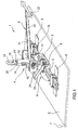
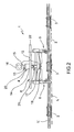
- the apparatus 2 comprises a support structure 2 having gripper means 3 for picking up and removably retaining a load C to be handled and means 4 for suspending the support structure 2 from and securing it to external transfer means (not shown).
- gripper means 3 for picking up and removably retaining a load C to be handled and means 4 for suspending the support structure 2 from and securing it to external transfer means (not shown).
- These may be, for example, an overhead crane, a hoist, a jib crane or a robot with a rope, a chain or other rigid and/or flexible attachment means, whereto the suspension means 4 may be removably connected.
- the gripper means 2 may be of various types, such as suction cups, magnets, hydraulic or pneumatic clamps.
- Guide means 5 are also provided between the suspension means 4 and the support structure 2 to allow rotation of the load about a substantially horizontal axis L, which may be fixed or movable with respect to the support structure 2. Furthermore, to promote rotation of the load C about the axis of rotation L and allow handling thereof, the apparatus 1 further comprises suitable driving means 6 adapted to apply a force to the load C.
- the driving means 6 may be designed for manual use by an operator or for automatic or semi-automatic use using a remote control.
- a peculiar aspect of the invention lies in that the guide means 5 are adapted to allow the assembly 7 formed by the load C and the support structure 2 to rotate about an axis of rotation L which is located at a minimum predetermined distance from the center of gravity G of the assembly 7. This will minimize the force to be applied to the driving means 6 to promote rotation of the load C about the center of gravity G.
- the guide means 5 may be dimensioned as a function of the particular application and/or the size of the load C.
- the minimum predetermined distance between the center of gravity G of the assembly 7 and the axis of rotation L may be comprised from 0 to 200 mm and is preferably less than about 20 mm, regardless of the angular position of the assembly 7 relative to the suspension means 4.
- the axis of rotation L may also be located inside the load C.
- the guide means 5 may further include at least one circular arc-shaped element 8, which is unitary or made of one piece with the support structure 2 and at least one roller 9 having a pin made of one piece with the suspension means 4.
- Each roller 9 and the corresponding circular arc-shaped element 8 may be so dimensioned that the roller 9 is able to roll along the circular arc-shaped element 8.
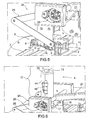
- This element may be a blind or through groove 11 formed on a corresponding plate 10, made of one piece with the support structure 2, as shown in FIG. 5 .
- the circular arc-shaped element 8 may be a relief formed on a plate unitary with the support structure, which defines an abutment surface for at least one corresponding roller 9.
- each circular arc-shaped element may be unitary or made of one piece with the suspension means 4 and each corresponding roller may have a pin made of one piece with the support structure 2.
- the guide means 5 may include at least one pair of adjacent rollers 9 disposed along the circular arc 8 and angularly offset from each other by a predetermined angle. Thanks to this feature, the distance between the axis of rotation L of the load C and the center of gravity of the assembly 7 is substantially constant through any angular position of the load C, thereby affording regular and safe handling of the load C.
- the arc-shaped element 8 may have such an angular extension as to allow the assembly 7 to rotate through a predetermined angle from 0 to substantially 360°.
- Such predetermined angle may have various values, depending on the types of applications and loads C.
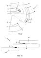
- the circular arc-shaped element 8 may extend through an angle substantially corresponding to a right angle increased by the offset angle between the rollers 9, so that the load C may be rotated by at least 90°.
- the guide means may include a plurality of telescopically coupled arc-shaped elements 8. This allows to increase the rotation angle of the assembly 7 to the maximum value of 360°, without excessively increasing the angular extension of the individual circular arc-shaped elements 8.
- the guide means 5 may include at least one four-bar linkage 8', having a pair of rockers 9'.
- Each rocker 9' may have one end hinged to the suspension means 4 and the other end hinged to the support structure 2 or to an extension 9" thereof.
- the hinge points and the lengths of rockers 9' may be selected so that the distance between the axis of rotation L and the center of gravity G of the assembly 7 meets the above minimum predetermined distance requirements.
- the support structure 2 may extend along a longitudinal axis L' substantially parallel to the axis of rotation L to provide a better grip of the load C.
- the support structure 2 may include at least a plurality of longitudinally offset guide means 5 to optimize the grip and handling of loads, even when the latter have a relatively large size.
- the suspension means 4 may include a telescopic element 12 having a substantially vertical telescopic direction during use. More in detail, the telescopic element 12 may have a stem 13, which is slideably received in a cylinder 14. The stem 13 may have an upper end 15 with a hook 16 for connection to the external handling means, whereas the cylinder 14 may have a lower end 17 attached to a frame 18 of the suspension means 4. Therefore, the frame 18 may be held by the cylinder 14 during use, and may be integral with the pins of the rollers 9 of the guide means 5, to also vertically hold the support structure 2.
- the telescopic element 12 may comprise an elastic member 19 between the stem 13 and the cylinder 14 so as to return the support structure 2 upwards. Thanks to its elastic hysteresis, the elastic member 19 allows to attenuate any impulsive or oscillatory stresses which might be transferred from the external handling means to the stem 13. Thanks to this arrangement, the attenuating action may be exerted during handling of the load C, whether it is a rotational, a translational or combined motion, and is effective both as the load C is lifted and as it is set down.
- the stem 13 may have indicator means (not shown) at the upper end 15, which project out of the upper edge 20 of the cylinder 14 when certain loads are applied to the elastic member 19.
- the indicator means may include a set of differentiated rings which are visible by an external operator as a function of the amount of the load C and to indicate any overload of the support structure 2. Thanks to this particular arrangement, the operator may be clearly and readily warned and the overall safety of the system will be increased. Furthermore, the visibility of the set of rings can solely depend on the mechanical properties of the elastic member 19, whereby no power supply or other supply is required for proper operation.
- other indicators may be used, such as a graduated scale, a color scale, symbols and pictograms.
- the driving means 6 may comprise a lever element 21 with an end handlebar 22 to be grasped by an operator.
- the lever element 21 may further have an adjustable length portion 23, allowing to adjust the distance between the operator and the support structure 2 as a function of the size of the load C, to improve the safety conditions or change the effort required by the operator.
- the adjustable portion 23 may be of the telescopic type, as shown in the annexed figures, or of the pantograph type (not shown), or of other types.
- the driving means 6 may further include a transmission mechanism 24, which is adapted to turn a rotation of the lever element 21 into a rotation of the load C with a predetermined transmission ratio, which may be of 1 or advantageously of more than 1. In the latter case, the angular travel of the lever element 21 may be reduced, thereby affording advantages in terms of safety. A reduced angular travel of the lever element 21 with respect to the horizontal limits the vertical traverse of the end handlebar 22 and increases the length of the adjustable portion 23, thereby allowing the operator to handle the load C from a longer distance and with a lower effort.
- the transmission mechanism 24 may include a linkage 25 and a gear train 26 or belt means (not shown). In certain embodiments (not shown), the driving means 6 may further include linear oil hydraulic or pneumatic actuators, to allow remote handling of the load C.
- the apparatus of the invention fulfills the proposed objects and particularly allows handling, even by hand, of loads of different size and weight in an easy, safe and convenient manner.
Landscapes
- Engineering & Computer Science (AREA)
- Mechanical Engineering (AREA)
- Physics & Mathematics (AREA)
- Geometry (AREA)
- Load-Engaging Elements For Cranes (AREA)
- Conveying And Assembling Of Building Elements In Situ (AREA)
- Water Treatment By Sorption (AREA)
- External Artificial Organs (AREA)
- Replacement Of Web Rolls (AREA)
- Manipulator (AREA)
Claims (14)
- Dispositif de manipulation de charges comprenant :- une structure de support (2) ayant des moyens preneurs (3) destinés à saisir et retenir de façon amovible une charge (C) à manipuler, ladite structure de support étant adaptée pour former, en combinaison avec la charge (C), un ensemble unitaire (7) possédant un centre de gravité (G) ;- des moyens (4) destinés à suspendre ladite structure de support (2) à des moyens de transfert extérieurs et à la fixer à ces moyens;- des moyens de guidage (5) situés entre lesdits moyens de suspension (4) et ladite structure de support (2) pour permettre la rotation de la charge (C) autour d'un axe sensiblement horizontal (L) ;- des moyens d'entraînement (6) destinés à appliquer une force à ladite charge (C) pour provoquer une rotation de celle-ci autour dudit axe (L) et à permettre à la charge (C) d'être manipulée ;- lesdits moyens de guidage (5) comprenant au moins un élément en forme d'arc de cercle (8) adapté pour faire tourner ledit ensemble (7) autour d'un axe de rotation (L), ledit axe de rotation (L) étant adapté pour être situé à une distance minime du centre de gravité (G) dudit ensemble (7), afin de réduire à un minimum la force qu'il faut appliquer auxdits moyens d'entraînement (6) pour provoquer la rotation de la charge (C) autour dudit centre de gravité (G) ;caractérisé en ce que lesdits moyens de guidage (5) comprennent une pluralité d'éléments en forme d'arc (8) accouplés télescopiquement pour atteindre un angle de rotation maximum qui est compris entre 0° et sensiblement 360°.
- Dispositif selon la revendication 1, caractérisé en ce que lesdits moyens de guidage comprennent en outre au moins une paire de rouleaux adjacents (9) disposés le long desdits éléments en forme d'arc (8) et déportés angulairement l'un par rapport à l'autre pour permettre à la charge (C) d'avoir seulement un degré de liberté en rotation.
- Dispositif selon la revendication 1, caractérisé en ce que ladite structure de support (2) s'étend le long d'un axe longitudinal (L') sensiblement parallèle audit axe de rotation (L), et il est prévu une pluralité desdits moyens de guidage (5) dans des positions décalées longitudinalement.
- Dispositif selon la revendication 1, caractérisé en ce que lesdits moyens de suspension (4) comprennent un élément télescopique (12) ayant une direction télescopique sensiblement verticale pendant l'utilisation.
- Dispositif selon la revendication 4, caractérisé en ce que ledit élément télescopique (12) comprend une tige (13) ayant une extrémité supérieure (15) munie d'un crochet (16) pour l'assemblage auxdits moyens de manipulation extérieurs, et qui est logée à coulissement dans un cylindre (14) ayant une extrémité inférieure (17) reliée auxdits moyens de guidage (5).
- Dispositif selon la revendication 5, caractérisé en ce que ledit élément télescopique (12) comprend un élément élastique (19) interposé entre ladite tige (13) et ledit cylindre (14) pour rappeler ladite structure de support (2) vers le haut.
- Dispositif selon la revendication 6, caractérisé en ce que ladite tige (13) possède des moyens indicateurs situés à l'extrémité supérieure (13) qui débordent en dehors du bord supérieur (20) dudit cylindre (14) lorsque certaines charges sont appliquées à l'élément élastique (19).
- Dispositif selon la revendication 7, caractérisé en ce que lesdits moyens indicateurs comprennent un jeu d'anneaux différenciés qui peuvent être vus par un opérateur extérieur en fonction de la valeur de la charge (C) qui est appliquée, et pour indiquer une éventuelle surcharge de la structure de support (2).
- Dispositif selon la revendication 1, caractérisé en ce que lesdits moyens d'entraînement (6) comprennent un élément formant levier (21) possédant un guidon terminal (22) destiné à être saisi par un opérateur.
- Dispositif selon la revendication 9, caractérisé en ce que ledit élément formant levier (21) possède une portion de longueur réglable (23) qui permet de régler la distance entre l'opérateur et la structure de support (2) en fonction de la dimension de la charge (C) afin d'améliorer les conditions de sécurité.
- Dispositif selon la revendication 10, caractérisé en ce que ladite portion réglable (23) est du type télescopique.
- Dispositif selon la revendication 10, caractérisé en ce que ladite portion réglable (23) est du type à pantographe.
- Dispositif selon la revendication 1, caractérisé en ce que lesdits moyens d'entraînement (6) comprennent un mécanisme de transmission (24) qui est adapté pour transformer une rotation dudit élément formant levier (21) en une rotation de la charge (C) avec un rapport de transmission prédéterminé.
- Dispositif selon la revendication 13, caractérisé en ce que ledit rapport de transmission est de 1 ou de plus de 1, pour réduire la trajectoire angulaire de l'élément formant levier (21).
Applications Claiming Priority (2)
| Application Number | Priority Date | Filing Date | Title |
|---|---|---|---|
| IT000277A ITVI20040277A1 (it) | 2004-12-03 | 2004-12-03 | Apparato per la manipolazione di carichi |
| PCT/IB2005/003404 WO2006059192A2 (fr) | 2004-12-03 | 2005-11-15 | Dispositif de manipulation de charges |
Publications (2)
| Publication Number | Publication Date |
|---|---|
| EP1828036A2 EP1828036A2 (fr) | 2007-09-05 |
| EP1828036B1 true EP1828036B1 (fr) | 2008-05-14 |
Family
ID=36565403
Family Applications (1)
| Application Number | Title | Priority Date | Filing Date |
|---|---|---|---|
| EP05811193A Expired - Lifetime EP1828036B1 (fr) | 2004-12-03 | 2005-11-15 | Dispositif de manipulation de charges |
Country Status (5)
| Country | Link |
|---|---|
| EP (1) | EP1828036B1 (fr) |
| AT (1) | ATE395282T1 (fr) |
| DE (1) | DE602005006844D1 (fr) |
| IT (1) | ITVI20040277A1 (fr) |
| WO (1) | WO2006059192A2 (fr) |
Families Citing this family (5)
| Publication number | Priority date | Publication date | Assignee | Title |
|---|---|---|---|---|
| ES2311362B1 (es) * | 2006-08-08 | 2009-12-02 | Fosgestal S.L. | Dispositivo para transportar y voltear cargas. |
| DE102013200146A1 (de) * | 2013-01-08 | 2014-07-10 | Robert Bosch Gmbh | Vorrichtung zum Entnehmen von plattenförmigen Elementen, insbesondere vonPappenzuschnitt |
| IT201700093692A1 (it) * | 2017-08-14 | 2019-02-14 | Metal Sud Di Merico Flavia Lucia | Attrezzo per il sollevamento e l'orientamento di oggetti. |
| CN113247755B (zh) * | 2021-06-07 | 2021-12-14 | 河南工学院 | 一种用于薄板吊运的起吊装置及包括其的起重机 |
| DE102021131288B4 (de) | 2021-11-29 | 2024-03-21 | DAL Real Estate Management GmbH | Greifanordnung zum Anheben und Versetzen von Hebegut |
Family Cites Families (6)
| Publication number | Priority date | Publication date | Assignee | Title |
|---|---|---|---|---|
| US3104016A (en) * | 1957-12-16 | 1963-09-17 | Alliance Machine Co | Coil handling crane |
| FR2645788B1 (fr) * | 1989-04-13 | 1995-07-28 | Sit Innovations Tech | Engin de telemanipulation prevu pour etre suspendu a une unite de levage |
| US5094495A (en) * | 1990-01-10 | 1992-03-10 | Littell Edmund R | Mechanism for lifting and orienting an object |
| DE4203151A1 (de) * | 1992-02-05 | 1993-08-12 | Iwe Spulentechnik Gmbh | Wendegeschirr zum wenden und heben von spulen und spulenaehnlichen koerpern |
| DE9313464U1 (de) * | 1993-08-31 | 1993-10-28 | Siemens AG, 80333 München | Hebezange für Gegenstände mit umfaßbarer Außenkontur |
| US5895198A (en) * | 1998-08-13 | 1999-04-20 | Lofstrom; Roger J. | Coil unloading rig |
-
2004
- 2004-12-03 IT IT000277A patent/ITVI20040277A1/it unknown
-
2005
- 2005-11-15 EP EP05811193A patent/EP1828036B1/fr not_active Expired - Lifetime
- 2005-11-15 WO PCT/IB2005/003404 patent/WO2006059192A2/fr not_active Ceased
- 2005-11-15 AT AT05811193T patent/ATE395282T1/de not_active IP Right Cessation
- 2005-11-15 DE DE602005006844T patent/DE602005006844D1/de not_active Expired - Fee Related
Also Published As
| Publication number | Publication date |
|---|---|
| WO2006059192A2 (fr) | 2006-06-08 |
| EP1828036A2 (fr) | 2007-09-05 |
| WO2006059192A3 (fr) | 2006-09-21 |
| DE602005006844D1 (de) | 2008-06-26 |
| ATE395282T1 (de) | 2008-05-15 |
| ITVI20040277A1 (it) | 2005-03-03 |
Similar Documents
| Publication | Publication Date | Title |
|---|---|---|
| KR20120115108A (ko) | 중력보상된 하중 바디를 자동적으로 움직이기 위한 방법 및 핸들링 시스템 | |
| US9676598B1 (en) | Gravity activated lifting claw | |
| CN114905543A (zh) | 用于机器人辅助设备的平衡机构 | |
| EP1828036A2 (fr) | Dispositif de manipulation de charges | |
| NL2005077C2 (en) | Self clamping lifting clamp. | |
| EP3002247A1 (fr) | Engin de manutention | |
| CN209988695U (zh) | 车辆钣金件的抓取机构和车辆钣金件的搬运设备 | |
| KR102809863B1 (ko) | 턴오버용 지그 | |
| CN210704823U (zh) | 一种机械手双杆式调节轴结构 | |
| CN110253607A (zh) | 一种可调节握力强度的机械手 | |
| CN211366697U (zh) | 吊具及升降机构 | |
| CN110980540B (zh) | 一种小型的短距离运输起重机 | |
| CN208394335U (zh) | 一种重型板材的上料装夹工具 | |
| CN108916584A (zh) | 一种相机多角度调节环绕机构 | |
| CN214298916U (zh) | 物料吊装治具及吊装装置 | |
| CN114074843A (zh) | 一种用于大重量物料上料的机械手装置 | |
| EP0890543A3 (fr) | Appareil de manutention de ISO containers par le côté | |
| CN210438280U (zh) | 新型石材夹具 | |
| CN114261878A (zh) | 一种起重机械用具有自动调整机构的吊钩组件 | |
| WO2011035405A1 (fr) | Dispositif de maintien universel | |
| EP2042465B1 (fr) | Dispositif de levage | |
| KR20140098623A (ko) | 리프트 장치 | |
| CN114538275A (zh) | 卷轴线缆搬运装置 | |
| CN216736394U (zh) | 传动轴搬运装置 | |
| JP6208578B2 (ja) | クレーン装置 |
Legal Events
| Date | Code | Title | Description |
|---|---|---|---|
| PUAI | Public reference made under article 153(3) epc to a published international application that has entered the european phase |
Free format text: ORIGINAL CODE: 0009012 |
|
| 17P | Request for examination filed |
Effective date: 20070629 |
|
| AK | Designated contracting states |
Kind code of ref document: A2 Designated state(s): AT BE BG CH CY CZ DE DK EE ES FI FR GB GR HU IE IS IT LI LT LU LV MC NL PL PT RO SE SI SK TR |
|
| GRAP | Despatch of communication of intention to grant a patent |
Free format text: ORIGINAL CODE: EPIDOSNIGR1 |
|
| DAX | Request for extension of the european patent (deleted) | ||
| GRAS | Grant fee paid |
Free format text: ORIGINAL CODE: EPIDOSNIGR3 |
|
| GRAA | (expected) grant |
Free format text: ORIGINAL CODE: 0009210 |
|
| AK | Designated contracting states |
Kind code of ref document: B1 Designated state(s): AT BE BG CH CY CZ DE DK EE ES FI FR GB GR HU IE IS IT LI LT LU LV MC NL PL PT RO SE SI SK TR |
|
| REG | Reference to a national code |
Ref country code: GB Ref legal event code: FG4D |
|
| REG | Reference to a national code |
Ref country code: CH Ref legal event code: EP |
|
| REG | Reference to a national code |
Ref country code: IE Ref legal event code: FG4D Free format text: LANGUAGE OF EP DOCUMENT: FRENCH |
|
| REF | Corresponds to: |
Ref document number: 602005006844 Country of ref document: DE Date of ref document: 20080626 Kind code of ref document: P |
|
| PG25 | Lapsed in a contracting state [announced via postgrant information from national office to epo] |
Ref country code: SI Free format text: LAPSE BECAUSE OF FAILURE TO SUBMIT A TRANSLATION OF THE DESCRIPTION OR TO PAY THE FEE WITHIN THE PRESCRIBED TIME-LIMIT Effective date: 20080514 |
|
| PG25 | Lapsed in a contracting state [announced via postgrant information from national office to epo] |
Ref country code: ES Free format text: LAPSE BECAUSE OF FAILURE TO SUBMIT A TRANSLATION OF THE DESCRIPTION OR TO PAY THE FEE WITHIN THE PRESCRIBED TIME-LIMIT Effective date: 20080825 Ref country code: FI Free format text: LAPSE BECAUSE OF FAILURE TO SUBMIT A TRANSLATION OF THE DESCRIPTION OR TO PAY THE FEE WITHIN THE PRESCRIBED TIME-LIMIT Effective date: 20080514 |
|
| NLV1 | Nl: lapsed or annulled due to failure to fulfill the requirements of art. 29p and 29m of the patents act | ||
| PG25 | Lapsed in a contracting state [announced via postgrant information from national office to epo] |
Ref country code: AT Free format text: LAPSE BECAUSE OF FAILURE TO SUBMIT A TRANSLATION OF THE DESCRIPTION OR TO PAY THE FEE WITHIN THE PRESCRIBED TIME-LIMIT Effective date: 20080514 Ref country code: NL Free format text: LAPSE BECAUSE OF FAILURE TO SUBMIT A TRANSLATION OF THE DESCRIPTION OR TO PAY THE FEE WITHIN THE PRESCRIBED TIME-LIMIT Effective date: 20080514 Ref country code: PL Free format text: LAPSE BECAUSE OF FAILURE TO SUBMIT A TRANSLATION OF THE DESCRIPTION OR TO PAY THE FEE WITHIN THE PRESCRIBED TIME-LIMIT Effective date: 20080514 Ref country code: LV Free format text: LAPSE BECAUSE OF FAILURE TO SUBMIT A TRANSLATION OF THE DESCRIPTION OR TO PAY THE FEE WITHIN THE PRESCRIBED TIME-LIMIT Effective date: 20080514 |
|
| PG25 | Lapsed in a contracting state [announced via postgrant information from national office to epo] |
Ref country code: IS Free format text: LAPSE BECAUSE OF FAILURE TO SUBMIT A TRANSLATION OF THE DESCRIPTION OR TO PAY THE FEE WITHIN THE PRESCRIBED TIME-LIMIT Effective date: 20080914 |
|
| PG25 | Lapsed in a contracting state [announced via postgrant information from national office to epo] |
Ref country code: DK Free format text: LAPSE BECAUSE OF FAILURE TO SUBMIT A TRANSLATION OF THE DESCRIPTION OR TO PAY THE FEE WITHIN THE PRESCRIBED TIME-LIMIT Effective date: 20080514 Ref country code: CZ Free format text: LAPSE BECAUSE OF FAILURE TO SUBMIT A TRANSLATION OF THE DESCRIPTION OR TO PAY THE FEE WITHIN THE PRESCRIBED TIME-LIMIT Effective date: 20080514 Ref country code: LT Free format text: LAPSE BECAUSE OF FAILURE TO SUBMIT A TRANSLATION OF THE DESCRIPTION OR TO PAY THE FEE WITHIN THE PRESCRIBED TIME-LIMIT Effective date: 20080514 Ref country code: SE Free format text: LAPSE BECAUSE OF FAILURE TO SUBMIT A TRANSLATION OF THE DESCRIPTION OR TO PAY THE FEE WITHIN THE PRESCRIBED TIME-LIMIT Effective date: 20080814 |
|
| PG25 | Lapsed in a contracting state [announced via postgrant information from national office to epo] |
Ref country code: PT Free format text: LAPSE BECAUSE OF FAILURE TO SUBMIT A TRANSLATION OF THE DESCRIPTION OR TO PAY THE FEE WITHIN THE PRESCRIBED TIME-LIMIT Effective date: 20081014 Ref country code: BE Free format text: LAPSE BECAUSE OF FAILURE TO SUBMIT A TRANSLATION OF THE DESCRIPTION OR TO PAY THE FEE WITHIN THE PRESCRIBED TIME-LIMIT Effective date: 20080514 Ref country code: RO Free format text: LAPSE BECAUSE OF FAILURE TO SUBMIT A TRANSLATION OF THE DESCRIPTION OR TO PAY THE FEE WITHIN THE PRESCRIBED TIME-LIMIT Effective date: 20080514 Ref country code: SK Free format text: LAPSE BECAUSE OF FAILURE TO SUBMIT A TRANSLATION OF THE DESCRIPTION OR TO PAY THE FEE WITHIN THE PRESCRIBED TIME-LIMIT Effective date: 20080514 |
|
| PLBE | No opposition filed within time limit |
Free format text: ORIGINAL CODE: 0009261 |
|
| STAA | Information on the status of an ep patent application or granted ep patent |
Free format text: STATUS: NO OPPOSITION FILED WITHIN TIME LIMIT |
|
| 26N | No opposition filed |
Effective date: 20090217 |
|
| PG25 | Lapsed in a contracting state [announced via postgrant information from national office to epo] |
Ref country code: BG Free format text: LAPSE BECAUSE OF FAILURE TO SUBMIT A TRANSLATION OF THE DESCRIPTION OR TO PAY THE FEE WITHIN THE PRESCRIBED TIME-LIMIT Effective date: 20080814 Ref country code: EE Free format text: LAPSE BECAUSE OF FAILURE TO SUBMIT A TRANSLATION OF THE DESCRIPTION OR TO PAY THE FEE WITHIN THE PRESCRIBED TIME-LIMIT Effective date: 20080514 |
|
| PG25 | Lapsed in a contracting state [announced via postgrant information from national office to epo] |
Ref country code: MC Free format text: LAPSE BECAUSE OF NON-PAYMENT OF DUE FEES Effective date: 20081130 |
|
| REG | Reference to a national code |
Ref country code: IE Ref legal event code: MM4A |
|
| PG25 | Lapsed in a contracting state [announced via postgrant information from national office to epo] |
Ref country code: IT Free format text: LAPSE BECAUSE OF FAILURE TO SUBMIT A TRANSLATION OF THE DESCRIPTION OR TO PAY THE FEE WITHIN THE PRESCRIBED TIME-LIMIT Effective date: 20080514 |
|
| REG | Reference to a national code |
Ref country code: FR Ref legal event code: ST Effective date: 20090731 |
|
| PG25 | Lapsed in a contracting state [announced via postgrant information from national office to epo] |
Ref country code: DE Free format text: LAPSE BECAUSE OF NON-PAYMENT OF DUE FEES Effective date: 20090603 Ref country code: IE Free format text: LAPSE BECAUSE OF NON-PAYMENT OF DUE FEES Effective date: 20081115 |
|
| REG | Reference to a national code |
Ref country code: CH Ref legal event code: PL |
|
| GBPC | Gb: european patent ceased through non-payment of renewal fee |
Effective date: 20091115 |
|
| PG25 | Lapsed in a contracting state [announced via postgrant information from national office to epo] |
Ref country code: HU Free format text: LAPSE BECAUSE OF FAILURE TO SUBMIT A TRANSLATION OF THE DESCRIPTION OR TO PAY THE FEE WITHIN THE PRESCRIBED TIME-LIMIT Effective date: 20081115 Ref country code: LU Free format text: LAPSE BECAUSE OF NON-PAYMENT OF DUE FEES Effective date: 20081115 Ref country code: CY Free format text: LAPSE BECAUSE OF FAILURE TO SUBMIT A TRANSLATION OF THE DESCRIPTION OR TO PAY THE FEE WITHIN THE PRESCRIBED TIME-LIMIT Effective date: 20080514 |
|
| PG25 | Lapsed in a contracting state [announced via postgrant information from national office to epo] |
Ref country code: TR Free format text: LAPSE BECAUSE OF FAILURE TO SUBMIT A TRANSLATION OF THE DESCRIPTION OR TO PAY THE FEE WITHIN THE PRESCRIBED TIME-LIMIT Effective date: 20080514 |
|
| PG25 | Lapsed in a contracting state [announced via postgrant information from national office to epo] |
Ref country code: GR Free format text: LAPSE BECAUSE OF FAILURE TO SUBMIT A TRANSLATION OF THE DESCRIPTION OR TO PAY THE FEE WITHIN THE PRESCRIBED TIME-LIMIT Effective date: 20080815 Ref country code: LI Free format text: LAPSE BECAUSE OF NON-PAYMENT OF DUE FEES Effective date: 20091130 Ref country code: CH Free format text: LAPSE BECAUSE OF NON-PAYMENT OF DUE FEES Effective date: 20091130 |
|
| PG25 | Lapsed in a contracting state [announced via postgrant information from national office to epo] |
Ref country code: GB Free format text: LAPSE BECAUSE OF NON-PAYMENT OF DUE FEES Effective date: 20091115 |
|
| PG25 | Lapsed in a contracting state [announced via postgrant information from national office to epo] |
Ref country code: FR Free format text: LAPSE BECAUSE OF NON-PAYMENT OF DUE FEES Effective date: 20081130 |