EP1828080B1 - Verfahren zur herstellung von butadien aus n-butan - Google Patents
Verfahren zur herstellung von butadien aus n-butan Download PDFInfo
- Publication number
- EP1828080B1 EP1828080B1 EP05849467A EP05849467A EP1828080B1 EP 1828080 B1 EP1828080 B1 EP 1828080B1 EP 05849467 A EP05849467 A EP 05849467A EP 05849467 A EP05849467 A EP 05849467A EP 1828080 B1 EP1828080 B1 EP 1828080B1
- Authority
- EP
- European Patent Office
- Prior art keywords
- stream
- butane
- gas
- hydrogen
- butadiene
- Prior art date
- Legal status (The legal status is an assumption and is not a legal conclusion. Google has not performed a legal analysis and makes no representation as to the accuracy of the status listed.)
- Expired - Lifetime
Links
Images

Classifications
-
- C—CHEMISTRY; METALLURGY
- C07—ORGANIC CHEMISTRY
- C07C—ACYCLIC OR CARBOCYCLIC COMPOUNDS
- C07C11/00—Aliphatic unsaturated hydrocarbons
- C07C11/12—Alkadienes
- C07C11/16—Alkadienes with four carbon atoms
- C07C11/167—1, 3-Butadiene
-
- C—CHEMISTRY; METALLURGY
- C07—ORGANIC CHEMISTRY
- C07C—ACYCLIC OR CARBOCYCLIC COMPOUNDS
- C07C5/00—Preparation of hydrocarbons from hydrocarbons containing the same number of carbon atoms
- C07C5/32—Preparation of hydrocarbons from hydrocarbons containing the same number of carbon atoms by dehydrogenation with formation of free hydrogen
- C07C5/327—Formation of non-aromatic carbon-to-carbon double bonds only
- C07C5/333—Catalytic processes
-
- C—CHEMISTRY; METALLURGY
- C07—ORGANIC CHEMISTRY
- C07C—ACYCLIC OR CARBOCYCLIC COMPOUNDS
- C07C5/00—Preparation of hydrocarbons from hydrocarbons containing the same number of carbon atoms
- C07C5/42—Preparation of hydrocarbons from hydrocarbons containing the same number of carbon atoms by dehydrogenation with a hydrogen acceptor
- C07C5/48—Preparation of hydrocarbons from hydrocarbons containing the same number of carbon atoms by dehydrogenation with a hydrogen acceptor with oxygen as an acceptor
Definitions
- the invention relates to a process for the preparation of butadiene from n-butane.
- Butadiene is an important basic chemical and is used for example for the production of synthetic rubbers (butadiene homopolymers, styrene-butadiene rubber or nitrile rubber) or for the production of thermoplastic terpolymers (acrylonitrile-butadiene-styrene copolymers). Butadiene is further converted to sulfolane, chloroprene and 1,4-hexamethylenediamine (over 1,4-dichlorobutene and adiponitrile). By dimerization of butadiene, vinylcyclohexene can also be produced, which can be dehydrogenated to styrene.
- Butadiene can be prepared by thermal cracking (steam cracking) of saturated hydrocarbons, usually starting from naphtha as the raw material. Steam cracking of naphtha produces a hydrocarbon mixture of methane, ethane, ethene, acetylene, propane, propene, propyne, allenes, butenes, butadiene, butynes, methylalls, C 5 and higher hydrocarbons.
- WO-A-2004/007408 discloses a process for producing butadiene from n-butane.
- the object of the invention is to provide a process for the preparation of butadiene from n-butane, incurred in the smallest possible extent coupling products.
- the inventive method is characterized by a particularly effective use of raw materials. Thus, losses of the raw material n-butane are minimized by recycling unreacted n-butane into the dehydrogenation.
- the coupling of non-oxidative catalytic dehydrogenation and oxidative dehydrogenation achieves a high butadiene yield.
- the process is characterized by high selectivity as compared to the production of butadiene by cracking. There are no by-products. It eliminates the costly separation of butadiene from the product gas mixture of the cracking process.
- a feed gas stream a containing n-butane is provided.
- n-butane-rich gas mixtures such as liquefied petroleum gas (LPG) are assumed to be the raw material.
- LPG contains essentially saturated C 2 -C 5 hydrocarbons. It also contains methane and traces of C 6 + hydrocarbons.
- the composition of LPG can vary widely.
- the LPG used contains at least 10% by weight of butane.
- a refined C 4 stream from crackers or refineries may be used.
- the separation of propane and optionally methane, ethane and C 5 + hydrocarbons takes place for example in one or more conventional rectification columns.
- a first column low boilers methane, ethane, propane
- a second column high boilers C 5 + hydrocarbons
- a stream containing butanes is obtained, from which isobutane is separated, for example, in a customary rectification column.
- the remaining stream containing n-butane is used as feed gas stream for the subsequent butane dehydrogenation.
- the separated isobutane stream may be subjected to isomerization.
- the isobutane-containing stream is fed into an isomerization reactor.
- the isomerization from isobutane to n-butane can be as in GB-A 2 018 815 be described described.
- An n-butane / isobutane mixture is obtained, which is fed into the n-butane / isobutane separation column.
- the separated isobutane stream can also be fed to a further use, for example, be used for the production of methacrylic acid, polyisobutene or methyl tert-butyl ether.
- the n-butane-containing feed gas stream a generally contains at least 60% by weight of n-butane, preferably at least 90% by weight of n-butane. In addition, it may contain C 1 -C 6 hydrocarbons as minor constituents.
- n-butane-containing feed gas stream is fed to a dehydrogenation zone and subjected to non-oxidative catalytic dehydrogenation.
- n-butane is partially dehydrogenated in a dehydrogenation reactor on a dehydrogenating catalyst to 1-butene and 2-butene, wherein butadiene is formed.
- hydrogen and small amounts of low boilers (methane, ethane, ethene, propane and propene) are obtained.
- CO 2 , water and nitrogen may also be present in the product gas mixture of the non-oxidative catalytic n-butane dehydrogenation.
- unreacted n-butane is present in the product gas mixture.
- the non-oxidative catalytic n-butane dehydrogenation can be carried out with or without oxygen-containing gas as a co-feed.
- it is carried out as an autothermal non-oxidative catalytic dehydrogenation with feed of oxygen as a co-feed.
- the heat required is generated directly in the reactor system by combustion of hydrogen and / or hydrocarbons in the presence of oxygen.
- a hydrogen-containing co-feed may additionally be admixed.
- Oxygen can be fed in as pure oxygen or as an oxygen-containing gas, for example as air.
- oxygen can be fed in as an oxygen-rich gas, generally with an oxygen content of at least 75% by volume, preferably at least 90% by volume.
- a suitable oxygen-containing gas is technically pure oxygen with an oxygen content of about 99 vol .-%.
- a feature of the non-oxidative mode of operation over an oxidative mode of operation is that no free hydrogen is formed during the oxidative dehydrogenation.
- the non-oxidative catalytic n-butane dehydrogenation can in principle be carried out in all reactor types and procedures known from the prior art.
- a comparatively comprehensive description of dehydrogenation processes suitable according to the invention also contains "Catalytica® ® Studies Division, Oxidative Dehydrogenation and Alternative Dehydrogenation Processes" (Study Number 4192 OD, 1993, 430 Ferguson Drive, Mountain View, California, 94043-5272, USA).
- a suitable reactor form is the fixed bed tube or tube bundle reactor. These include the catalyst (dehydrogenation catalyst and, when working with oxygen as a co-feed, optionally special oxidation catalyst) as a fixed bed in a reaction tube or in a bundle of reaction tubes.
- the reaction tubes are usually heated indirectly by burning a gas, for example a hydrocarbon such as methane, in the space surrounding the reaction tubes. It is advantageous to apply this indirect form of heating only to the first about 20 to 30% of the length of the fixed bed and to heat the remaining bed length by the released in the context of indirect heating radiant heat to the required reaction temperature.
- Typical reaction tube internal diameters are about 10 to 15 cm.
- a typical Dehydrierrohrbündelreaktor comprises about 300 to 1000 reaction tubes.
- the temperature inside the reaction tube usually moves in the range of 300 to 1200 ° C, preferably in the range of 500 to 1000 ° C.
- the working pressure is usually between 0.5 and 8 bar, often between 1 and 2 bar when using a low water vapor dilution (analogous to the Linde process for propane dehydrogenation), but also between 3 and 8 bar when using a high steam dilution (analogous to so-called “steam active reforming process” (STAR process) for the dehydrogenation of propane or butane by Phillips Petroleum Co., see US 4,902,849 . US 4,996,387 and US 5,389,342 ).
- Typical catalyst loads (GHSV) are 500 to 2000 h -1 , based on the hydrocarbon used.
- the catalyst geometry can be, for example, spherical or cylindrical (hollow or full).
- the non-oxidative catalytic n-butane dehydrogenation can also, as in Chem. Eng. Sci. 1992b, 47 (9-11) 2313 described heterogeneously catalyzed be carried out in a fluidized bed.
- two fluidized beds are operated side by side, one of which is usually in the state of regeneration.
- the working pressure is typically 1 to 2 bar, the dehydrogenation temperature usually 550 to 600 ° C.
- the heat required for the dehydrogenation is introduced into the reaction system in that the dehydrogenation catalyst is preheated to the reaction temperature.
- an oxygen-containing co-feed can be dispensed with the preheater, and the heat required directly in the reactor system by combustion of hydrogen and / or hydrocarbons in the presence of oxygen are generated.
- a hydrogen-containing co-feed may additionally be admixed.
- the non-oxidative catalytic n-butane dehydrogenation can be carried out with or without oxygen-containing gas as a co-feed in a tray reactor. Preferably, it is carried out with oxygen-containing gas as a co-feed.
- the number of catalyst beds may be 1 to 20, advantageously 1 to 6, preferably 1 to 4 and in particular 1 to 3.
- the catalyst beds are preferably flowed through radially or axially from the reaction gas.
- such a tray reactor is operated with a fixed catalyst bed.
- the fixed catalyst beds are arranged in a shaft furnace reactor axially or in the annular gaps of concentrically arranged cylindrical gratings.
- a shaft furnace reactor corresponds to a horde.
- the implementation of the dehydrogenation in a single shaft furnace reactor corresponds to a preferred embodiment, wherein it is possible to work with an oxygen-containing co-feed.
- the dehydrogenation is carried out in a tray reactor with 3 catalyst beds.
- the reaction gas mixture in the tray reactor is subjected to intermediate heating on its way from one catalyst bed to the next catalyst bed, e.g. by passing over heated with hot gases heat exchanger surfaces or by passing through heated with hot fuel gases pipes.
- the non-oxidative catalytic n-butane dehydrogenation is carried out autothermally.
- oxygen is added to the reaction gas mixture of the n-butane dehydrogenation in at least one reaction zone in addition to that contained in the reaction gas mixture Hydrogen and / or hydrocarbon is at least partially combusted, whereby at least a portion of the required Dehydriershire in the at least one reaction zone is generated directly in the reaction gas mixture.
- the amount of the oxygen-containing gas added to the reaction gas mixture is selected such that the amount of heat required for the dehydrogenation of the n-butane is produced by the combustion of hydrogen present in the reaction gas mixture and optionally of hydrocarbons present in the reaction gas mixture and / or of carbon present in the form of coke is produced.
- the total amount of oxygen fed, based on the total amount of butane is 0.001 to 0.5 mol / mol, preferably 0.005 to 0.2 mol / mol, particularly preferably 0.05 to 0.2 mol / mol.
- Oxygen can be used either as pure oxygen or as an oxygen-containing gas mixed with inert gases, for example in the form of air.
- the oxygen-containing gas contains at least 70% by volume, more preferably at least 95% by volume of oxygen, in order to minimize the inert gas content in the product gas stream of the autothermal dehydrogenation.
- the inert gases and the resulting combustion gases also have a diluting effect and thus promote heterogeneously catalyzed dehydrogenation.
- the hydrogen burned to generate heat is the hydrogen formed during the catalytic n-butane dehydrogenation and optionally additionally hydrogen added to the reaction gas mixture as the hydrogen-containing gas.
- sufficient hydrogen should be present so that the molar ratio H 2 / O 2 in the reaction gas mixture immediately after the introduction of oxygen is 1 to 10, preferably 2 to 5 mol / mol. This applies to multi-stage reactors for each intermediate feed of oxygen-containing and possibly hydrogen-containing gas.
- the hydrogen combustion takes place catalytically.
- the dehydrogenation catalyst used generally also catalyzes the combustion of the hydrocarbons and of hydrogen with oxygen, so that in principle no special oxidation catalyst different from this one is required.
- the reaction is carried out in the presence of one or more oxidation catalysts which selectively catalyze the combustion of hydrogen with oxygen in the presence of hydrocarbons.
- the combustion of these hydrocarbons with oxygen to CO 2 and water is therefore only to a minor extent.
- the dehydrogenation catalyst and the oxidation catalyst are present in different reaction zones.
- the oxidation catalyst may be present in only one, in several or in all reaction zones.
- the catalyst which selectively catalyzes the oxidation of hydrogen is disposed at the sites where higher oxygen partial pressures prevail than at other locations of the reactor, particularly near the oxygen-containing gas feed point.
- the feeding of oxygen-containing gas and / or hydrogen-containing gas can take place at one or more points of the reactor.
- an intermediate feed of oxygen-containing gas and optionally of hydrogen-containing gas takes place before each tray of a tray reactor.
- the feed of oxygen-containing gas and optionally of hydrogen-containing gas takes place before each horde except the first Horde.
- behind each feed point is a layer of a specific oxidation catalyst, followed by a layer of the dehydrogenation catalyst.
- no special oxidation catalyst is present.
- the dehydrogenation temperature is generally 400 to 1100 ° C
- the pressure in the last catalyst bed of the tray reactor generally 0.2 to 5 bar, preferably 1 to 3 bar.
- the load (GHSV) is generally 500 to 2000 h -1 , in high load mode also up to 100 000 h -1 , preferably 4000 to 16 000 h -1 .
- a preferred catalyst which selectively catalyzes the combustion of hydrogen contains oxides and / or phosphates selected from the group consisting of the oxides and / or phosphates of germanium, tin, lead, arsenic, antimony or bismuth.
- Another preferred catalyst which catalyzes the combustion of hydrogen contains a noble metal of VIII. And / or I. Maury.
- the dehydrogenation catalysts used generally have a carrier and an active composition.
- the carrier is usually made of a heat-resistant oxide or mixed oxide.
- the dehydrogenation catalysts contain a metal oxide selected from the group consisting of zirconium dioxide, zinc oxide, alumina, silica, titania, magnesia, lanthana, ceria and mixtures thereof as a carrier.
- the mixtures may be physical mixtures or chemical mixed phases such as magnesium or zinc-aluminum oxide mixed oxides act.
- Preferred supports are zirconia and / or silica, particularly preferred are mixtures of zirconia and silica.
- the active composition of the dehydrogenation catalysts generally contain one or more elements of VIII. Subgroup, preferably platinum and / or palladium, more preferably platinum.
- the dehydrogenation catalysts may comprise one or more elements of main group I and / or II, preferably potassium and / or cesium.
- the dehydrogenation catalysts may contain one or more elements of III. Subgroup including the lanthanides and actinides, preferably lanthanum and / or cerium.
- the dehydrogenation catalysts may contain one or more elements of III. and / or IV.
- Main group preferably one or more elements from the group consisting of boron, gallium, silicon, germanium, tin and lead, particularly preferably tin.
- the dehydrogenation catalyst contains at least one element of the VIII. Subgroup, at least one element of the I. and / or II. Main group, at least one element of III. and / or IV. Main group and at least one element of III. Subgroup including the lanthanides and actinides.
- all dehydrogenation catalysts can be used, which in the WO 99/46039 . US 4,788,371 . EP-A 705,136 . WO 99/29420 . US 5,220,091 . US 5,430,220 . US 5,877,369 . EP 0 117 146 . DE-A 199 37 106 . DE-A 199 37 105 and DE-A 199 37 107 be revealed.
- Particularly preferred catalysts for the above-described variants of the autothermal n-butane dehydrogenation are the catalysts according to Examples 1, 2, 3 and 4 of DE-A 199 37 107 ,
- the n-butane dehydrogenation is preferably carried out in the presence of steam.
- the added water vapor serves as a heat carrier and supports the gasification of organic deposits on the catalysts, whereby the coking of the catalysts counteracted and the service life of the catalysts is increased.
- the organic deposits are converted into carbon monoxide, carbon dioxide and possibly water.
- the dehydrogenation catalyst can be regenerated in a manner known per se.
- steam can be added to the reaction gas mixture or, from time to time, an oxygen-containing gas can be passed over the catalyst bed at elevated temperature and the deposited carbon burned off.
- an oxygen-containing gas can be passed over the catalyst bed at elevated temperature and the deposited carbon burned off.
- the catalyst is reduced after regeneration with a hydrogen-containing gas.
- n-butane dehydrogenation In the non-oxidative catalytic n-butane dehydrogenation, a gas mixture is obtained, which in addition to butadiene 1-butene, 2-butene and unreacted n-butane contains minor constituents. Common secondary constituents are hydrogen, water vapor, nitrogen, CO and CO 2 , methane, ethane, ethene, propane and propene.
- the composition of the gaseous mixture leaving the first dehydrogenation zone can vary widely depending on the mode of dehydrogenation.
- the product gas mixture When carrying out the preferred autothermal dehydrogenation with the introduction of oxygen and additional hydrogen, the product gas mixture has a comparatively high content of water vapor and carbon oxides.
- the product gas mixture of the non-oxidative dehydrogenation When operating without oxygen feed, the product gas mixture of the non-oxidative dehydrogenation has a comparatively high content of hydrogen.
- the product gas stream of the n-butane nonoxidative autothermal dehydrogenation typically contains 0.1 to 15% by volume of butadiene, 1 to 20% by volume of 1-butene, 1 to 40% by volume of 2-butene (cis / trans 2-butene), 20 to 70% by volume of n-butane, 1 to 70% by volume of steam, 0 to 10% by volume of low-boiling hydrocarbons (methane, ethane, ethene, propane and propene), 0.1 to 40% by volume of hydrogen, 0 to 70% by volume of nitrogen and 0 to 10% by volume of carbon dioxide.
- the product gas stream b leaving the first dehydrogenation zone can be separated into two partial streams, wherein only one of the two partial streams is subjected to the further process parts C to H and the second partial stream is returned to the first dehydrogenation zone.
- a corresponding procedure is in DE-A 102 11 275 described.
- the non-oxidative catalytic dehydrogenation according to the invention is followed by an oxidative dehydrogenation (oxydehydrogenation) as process part C.
- oxidative dehydrogenation oxydehydrogenation
- 1-butene and 2-butene are dehydrogenated to 1,3-butadiene, with 1-butene generally reacting almost completely.
- n-butenes ratio a gas mixture which has a molar oxygen: n-butenes ratio of at least 0.5. Preference is given to working at an oxygen: n-butenes ratio of 0.55 to 50.
- the product gas mixture originating from the non-oxidative catalytic dehydrogenation is generally mixed with pure oxygen or an oxygen-containing gas.
- the oxygen-containing gas may be air or contain predominantly oxygen, generally at least 70% by volume, preferably at least 95% by volume, in order to minimize the inert gas content in the product gas stream of the oxydehydrogenation.
- Preferred is technically pure oxygen. This usually contains at least 99% by volume of oxygen.
- the catalysts which are particularly suitable for the oxydehydrogenation are generally based on a Mo-Bi-O-containing multimetal oxide system, which as a rule also contains iron.
- the catalyst system contains further additional components from the 1st to 15th group of the Periodic Table, such as potassium, magnesium, zirconium, chromium, nickel, cobalt, cadmium, tin, lead, germanium, lanthanum, manganese, tungsten, phosphorus, Cerium, aluminum or silicon.
- a Mo-Bi-Fe-O-containing multimetal oxide system is used, with a Mo-Bi-Fe-Cr-O or Mo-Bi-Fe-Zr-O-containing multimetal oxide system being particularly preferred
- Preferred systems are described, for example, in US 4,547,615 (Mo 12 BiFe 0.1 Ni 8 ZrCr 3 K 0.2 O x and Mo 12 BiFe 0.1 Ni 8 AlCr 3 K 0.2 O x ), US 4,424,141 (Mo 12 BiFe 3 CO 0.4 Ni 2.5 P 0.5 K 0.1 O x + SiO 2 DE-A 25 30 959 (Mo 12 BiFe 3 Co 4.5 Ni 2.5 Cr 0.5 K 0.1 O x , Mo 13.75 BiFe 3 Co 4.5 N1 2.5 Ge 0.5 K 0.8 O x , Mo 12 BiFe 3 Co 4.5 Ni 2.5 Mn 0.5 K 0.1 O x and Mo 12 BiFe
- the oxydehydrogenation catalyst is generally used as a shaped article having an average size of over 2 mm. Due to the pressure loss to be observed during the practice of the method smaller moldings are generally unsuitable. Examples of suitable shaped bodies are tablets, cylinders, hollow cylinders, rings, balls, strands, carriage wheels or extrudates. Special forms, such as "Trilobes” and “Tristars” (see EP-A-0 593 646 ) or molded body with at least one notch on the outside (see US 5,168,090 ) are also possible.
- the catalyst used can be used as a so-called full catalyst.
- the entire shaped catalyst body consists of the active material, including any auxiliaries, such as graphite or pore former, and other components.
- any auxiliaries such as graphite or pore former, and other components.
- Mo-Bi-Fe-O-containing catalyst preferably used for the oxydehydrogenation of the n-butenes to butadiene as a full catalyst.
- the active materials of the catalysts on a support such as an inorganic, oxidic Shaped body to apply.
- Such catalysts are usually referred to as shell catalysts.
- the oxydehydrogenation is generally carried out at a temperature of 220 to 490 ° C, and preferably 250 to 450 ° C. It chooses a reactor input pressure sufficient to overcome the existing in the system and the subsequent work-up flow resistance.
- This reactor inlet pressure is usually 0.005 to 1 MPa gauge, preferably 0.01 to 0.5 MPa gauge. Naturally, the gas pressure applied in the inlet area of the reactor largely drops over the entire catalyst bed.
- the product gas stream c leaving the oxidative dehydrogenation contains, in addition to butadiene and unreacted n-butane, hydrogen, carbon dioxide and water vapor. As minor constituents, it may also contain oxygen, nitrogen, methane, ethane, ethene, propane and propene and oxygen-containing hydrocarbons, so-called oxygenates. In general, it contains virtually no 1-butene and only small amounts of 2-butene.
- the product gas stream leaving the oxidative dehydrogenation comprises c 1 to 40% by volume of butadiene, 1 to 80% by volume of n-butane, 0 to 5% by volume of 2-butene, 0 to 1% by volume 1 Butene, 5 to 70% by volume of steam, 0 to 10% by volume of low-boiling hydrocarbons (methane, ethane, ethene, propane and propene), 0.1 to 15% by volume of hydrogen, 0 to 40% by volume Nitrogen, 0 to 10 vol .-% carbon dioxide and 0 to 10 vol .-% oxygenates on.
- Oxygenates may be, for example, furan, acetic acid, maleic anhydride, maleic acid, propionic acid, acetaldehyde, acrolein, formaldehyde, formic acid and butyraldehyde.
- acetylene, propyne and 1,2-butadiene may be present in traces.
- the product gas stream c may still contain small amounts of oxygen. If the product gas stream c contains more than just minor traces of oxygen, a process stage for removing residual oxygen from the product gas stream c is generally carried out.
- the residual oxygen can have a disturbing effect insofar as it can act as an initiator for polymerization reactions in downstream process steps. This danger is particularly present in the distillative removal of butadiene (step E)) and can there lead to deposits of polymers (formation of so-called "popcorn") in the extractive distillation column.
- the oxygen removal is performed immediately after the oxidative dehydrogenation.
- a catalytic combustion stage is carried out in which oxygen is reacted with the hydrogen contained in the gas stream c in the presence of a catalyst. As a result, a reduction in the oxygen content is achieved down to a few traces.
- Platinum and tin are advantageously used in a weight ratio of 1: 4 to 1: 0.2, preferably in a ratio of 1: 2 to 1: 0.5, in particular in a ratio of approximately 1: 1.
- the catalyst contains 0.05 to 0.09 wt .-% platinum and 0.05 to 0.09 wt .-% tin based on the total weight of the catalyst.
- the alumina catalyst contains only platinum and tin.
- the catalyst support of ⁇ -alumina advantageously has a BET surface area of 0.5 to 15 m 2 / g, preferably 2 to 14 m 2 / g, in particular 7 to 11 m 2 / g.
- the carrier used is preferably a shaped body. Preferred geometries are, for example, tablets, ring tablets, spheres, cylinders, star strands or gear-shaped strands with diameters of 1 to 10 mm, preferably 2 to 6 mm. Particularly preferred are balls or cylinders, in particular cylinders.
- Alternative methods for removing residual oxygen from the product gas stream c include contacting the product gas stream with a mixture of metal oxides containing copper in oxidation state 0 in a reduced form.
- a mixture of metal oxides containing copper in oxidation state 0 in a reduced form generally still contains aluminum oxides and zinc oxides, wherein the copper content is usually up to 10 wt .-%. In this way, almost complete separation of residual oxygen is possible.
- you can other methods of removing traces of oxygen are used. Examples are the separation by means of molecular sieves or using membranes.
- the gas stream c is compressed in at least one first compression stage and then cooled, whereby at least one condensate stream d1 containing water condenses out and a gas stream d2 containing n-butane, butadiene, hydrogen, carbon dioxide and water vapor remains.
- the gas stream c is cooled to a temperature in the range of 15 to 60 ° C before the first compression stage. Cooling takes place by direct or indirect heat exchange. In the case of direct heat exchange, recirculated condensate is brought into contact with the gas stream c. Suitable contact devices are wash columns, quench columns, venturi scrubbers. Optionally, NaNO 2 is added to the quench recycle stream to remove traces of oxygen. Optionally, the quench circulating amount of stabilizer is added against the formation of popcorn, polymers or butadiene peroxides.
- the compression can be done in one or more stages. Overall, it is compressed from a pressure in the range of 1.0 to 4.0 bar to a pressure in the range of 3.5 to 8.0 bar. After each compression stage is followed by a cooling step, in which the gas stream is cooled to a temperature in the range of 15 to 60 ° C.
- the condensate stream d1 can thus also comprise a plurality of streams in the case of multistage compression.
- the gas stream d2 is generally essentially of C 4 hydrocarbons (essentially n-butane and butadiene), hydrogen, carbon dioxide and water vapor. In addition, the stream d2 may still contain low boilers and inert gases (nitrogen) as further secondary components.
- the wastewater stream d1 is generally at least 80 wt .-%, preferably at least 90 wt .-% of water and also contains low levels of low boilers, C 4 hydrocarbons, oxygenates and carbon dioxide.
- Suitable compressors are, for example, turbo, rotary piston and reciprocating compressors.
- the compressors can be driven, for example, with an electric motor, an expander or a gas or steam turbine.
- Typical compression ratios (outlet pressure: inlet pressure) per compressor stage are between 1.5 and 3.0, depending on the design.
- the cooling of the compressed gas takes place with heat exchangers, which can be designed, for example, as a tube bundle, spiral or plate heat exchanger.
- heat exchangers which can be designed, for example, as a tube bundle, spiral or plate heat exchanger.
- coolant cooling water or heat transfer oils are used in the heat exchangers.
- air cooling is preferably used using blowers.
- the gas stream d2 is separated by extractive distillation into a product stream e1 consisting essentially of butadiene and a stream e2 containing n-butane, hydrogen, carbon dioxide and water vapor.
- the extractive distillation can be carried out, for example, as described in Petroleum and Coal - Natural Gas - Petrochemical Volume 34 (8), pages 343 - 346 or Ullmanns Enzyklopadie der Technischen Chemie, Volume 9, 4th edition 1975, pages 1 to 18.
- the gas stream d2 is brought into contact with an extraction agent, preferably an N-methylpyrrolidone (NMP) / water mixture, in an extraction zone.
- NMP N-methylpyrrolidone
- the extraction zone is generally carried out in the form of a wash column which contains trays, fillers or packings as internals. This generally has 30 to 70 theoretical plates, so that a sufficiently good release effect is achieved.
- the wash column has a backwash zone in the column head. This backwash zone serves to recover the extractant contained in the gas phase by means of liquid hydrocarbon reflux, to which the top fraction is condensed beforehand. Typical temperatures at the top of the column are between 30 and 60 ° C.
- the mass ratio extractant to C 4 product gas stream d2 in the feed of the extraction zone is generally from 10: 1 to 20: 1.
- Suitable extractants are butyrolactone, nitriles such as acetonitrile, propionitrile, methoxypropionitrile, ketones such as acetone, furfural, N-alkyl-substituted lower aliphatic acid amides such as dimethylformamide, diethylformamide, dimethylacetamide, diethylacetamide, N-formylmorpholine, N-alkyl-substituted cyclic acid amides (lactams) such as N-alkylpyrrolidones , in particular N-methylpyrrolidone (NMP).
- NMP N-methylpyrrolidone
- alkyl-substituted lower aliphatic acid amides or N-alkyl substituted cyclic acid amides are used.
- Particularly advantageous are dimethylformamide, acetonitrile, furfural and in particular NMP.
- mixtures of these extractants with each other for.
- mixtures of these extractants with cosolvents and / or tert-butyl ether e.g. As methyl tert-butyl ether, ethyl tert-butyl ether, propyl tert-butyl ether, n- or iso-butyl tert-butyl ether can be used.
- Particularly suitable is NMP, preferably in aqueous solution, preferably with 0 to 20 wt .-% water, particularly preferably with 7 to 10 wt .-% water, in particular with 8.3 wt .-% water.
- the extractive distillation column In the extractive distillation column is a gaseous, n-butane, water vapor, hydrogen and carbon dioxide-containing stream e2, which is generally withdrawn via the top of the column, and as side draw stream, a mixture of extractant and butadiene won. From this mixture butadiene can be subsequently obtained as a pure product.
- the bottom withdrawing stream is the extractant, which still contains butadiene and optionally secondary components (impurities).
- the bottom draw stream is recycled, optionally after carrying out further purification steps, back into the extractive distillation.
- the stream e2 may contain, as further constituents, butenes, low boilers and inert gases (nitrogen).
- the extractive distillation, isolation of the pure butadiene and purification of the extractant can be carried out as follows: the side draw stream of the extractive distillation column of extractant and butadiene, which also contains impurities (acetylene, propyne, 1,2-butadiene), is fed into a wash column, which is charged with fresh extractant. Crude butadiene, which contains, for example, 98% by weight of butadiene, is withdrawn from the column top of the wash column. The bottom draw stream is enriched with acetylene and is recycled to the extractive distillation.
- the crude butadiene may contain as impurities propyne and 1,2-butadiene.
- the crude butadiene is fed to a first purifying distillation column and a butadiene stream enriched with propyne is separated off at the top.
- the bottom draw stream which is essentially propyne-free but still contains traces of 1,2-butadiene, is fed to a second pure distillation column in which a substantially 1,2-butadiene-free pure butadiene stream having a purity of, for example, at least 99.6 wt .-% as top draw or side draw stream in the enrichment section of the column and a 1,2-butadiene-enriched bottom draw stream can be obtained.
- the extraction solution is transferred to a desorption zone with reduced pressure and / or elevated temperature relative to the extraction zone, desorbing from the extraction solution butadiene and any traces of acetylene present.
- the desorption zone can be designed, for example, in the form of a wash column which has 5 to 15, preferably 8 to 10 theoretical stages and a backwash zone with, for example, 4 theoretical stages. This backwash zone is used to recover the extractant contained in the gas phase by means of liquid hydrocarbon reflux, to which the top fraction is condensed beforehand.
- internals packings, trays or packing are provided.
- the pressure at the top of the column is for example 1.5 bar.
- the temperature in the bottom of the column is for example 130 to 150 ° C.
- a substantially acetylene-free extractant is obtained, which is recycled to the extractive distillation column.
- the desired product stream e1 as obtained, for example, as the top draw stream of the second pure distillation column, can contain up to 100% by volume of butadiene.
- the extraction solution is transferred to a desorption zone with reduced pressure and / or elevated temperature relative to the extraction zone, the butadiene being desorbed from the extraction solution.
- the desorption zone can be designed, for example, in the form of a wash column which has 5 to 15, preferably 8 to 10 theoretical stages and a backwash zone with, for example, 4 theoretical stages. This backwash zone is used to recover the extractant contained in the gas phase by means of liquid hydrocarbon reflux, to which the top fraction is condensed beforehand. As internals packings, trays or packing are provided.
- the pressure at the top of the column is for example 1.5 bar.
- the temperature in the bottom of the column is for example 130 to 150 ° C.
- the gas stream e2 is compressed in at least one further compression stage and then cooled, at least one condensate stream f1 containing n-butane and water and a gas stream f2 containing n-butane, hydrogen and carbon dioxide being obtained,
- the compression can again be done in one or more stages. In general, a total pressure of from 3.5 to 8 bar is compressed to a pressure in the range of 12 to 40 bar. After each compression stage is followed by a cooling step, in which the gas stream is cooled to a temperature in the range of 15 to 60 ° C.
- a cooling step in which the gas stream is cooled to a temperature in the range of 15 to 60 ° C.
- the Condensate flow f1 can thus also comprise a plurality of streams in the case of multistage compression.
- the compression is carried out in two stages, wherein in a first compression stage to a pressure of 8 to 15 bar and in a second compression stage to a pressure of 12 to 40 bar is compressed. After each compression stage, a cooling stage (intermediate cooling) takes place, in each case a condensate stream is obtained. These are fed together or separately to the phase separation.
- the gas stream f2 generally contains n-butane, carbon dioxide and hydrogen as essential components. In addition, it may still contain butenes, low boilers and inert gases (nitrogen) as additional secondary components. Even steam can still be present in small quantities.
- the condensate stream f1 is generally at least 40 wt .-%, preferably at least 60 wt .-% of C 4 hydrocarbons (essentially n-butane, next possibly also stillene) and also contains water and in general still carbon dioxide, furthermore, he can still contain low-boiling and oxygenates.
- a condensate stream g1 containing n-butane and an exhaust gas stream g2 containing carbon dioxide and hydrogen are obtained.
- the condensation can be carried out in several stages, for example in two stages or else as a rectification with 5 to 15 theoretical stages. In this case, a plurality of condensate flows g1 can be obtained.
- the condensate stream g1 can be condensed out, for example, in surface condensers.
- the gas flow f2 comes into contact with tubes through which a cooling medium flows.
- a cooling medium for example, water, air and cooling brine into consideration.
- Injection condensers in which the coolant, preferably water, directly into the gas stream, which contains the components to be condensed, injected, are possible.
- the gas stream f2 is cooled to a temperature in the range of -30 to +20 ° C.
- the condensate stream g1 predominantly contains C 4 -hydrocarbons (essentially n-butane and optionally butenes), generally at least 50% by weight, preferably at least 70% by weight, and in addition also generally contains carbon dioxide. He may also contain low boilers and small amounts of water.
- water is separated from the at least one condensate stream f1 and optionally the condensate stream g1 by phase separation, at least one recycle stream h1 containing n-butane and at least one wastewater stream h2 being obtained, and the at least one recycle stream h1 is introduced into the first dehydrogenation zone recycled.
- the condensate streams f1 and optionally g1 are supplied separately or combined to one or more phase separation apparatuses.
- the condensate stream g1 is subjected to a phase separation, if it still has a significant water content, otherwise it can be recycled directly into the first dehydrogenation zone.
- One or more separate C 4 hydrocarbon streams h1 are obtained.
- the hydrocarbon stream (s) h1 contain predominantly C 4 hydrocarbons (essentially n-butane, optionally also butenes), generally at least 70% by weight, preferably at least 80% by weight, and may additionally contain carbon dioxide, low boilers and Contain traces of water.
- the waste water stream h2 contains predominantly water, generally at least 65 wt .-%, and in addition also generally contains carbon dioxide.
- hydrocarbons (low boilers and C 4 hydrocarbons) may be included.
- the one or more separated by phase separation hydrocarbon streams h1 and optionally the stream g1 are partially or completely recycled to the first dehydrogenation zone.
- the exhaust stream g2 contains generally predominantly carbon dioxide and optionally inert gases, besides hydrogen, to a small extent C 4 hydrocarbons and optionally low boilers.
- phase separation is preferably carried out in the earth's gravity field in a horizontal or stationary phase separator.
- the phase separator may contain sedimentation aids (eg fillers or plates) or coalescing filters (eg of fiber material).
- the hydrogen contained in the exhaust gas stream g2 may be passed, optionally after cooling, for example in an indirect heat exchanger, via a membrane, which is usually designed as a tube, which is permeable only to molecular hydrogen.
- a membrane which is usually designed as a tube, which is permeable only to molecular hydrogen.
- the thus separated molecular hydrogen can, if necessary, at least partially used in the dehydrogenation or else be supplied to another utilization, for example, be used for generating electrical energy in fuel cells.
- An n-butane containing feed gas stream (4) obtained by combining a fresh gas stream (1) and a recycle stream (15) is fed to the first autothermally operated n-butane non-oxidative catalytic dehydrogenation (BDH) stage (18) ,
- BDH non-oxidative catalytic dehydrogenation
- hydrogen is selectively burned.
- combustion air is supplied as stream (2).
- water vapor (3) is added.
- a dehydrogenation gas mixture (5) is obtained which, after leaving the autothermal dehydrogenation stage (18), is cooled and fed to the second oxidative n-butane dehydrogenation stage (ODH) (19).
- the second dehydrogenation stage (19) is further supplied with an oxygen stream (6).
- the conversion ratios and selectivities shown in Table 1 were assumed based on experimental results.
- the condensate (12) falls at a pressure of 12 bar and a temperature of 55 ° C
- the condensate (14a) falls at a pressure of 30.1 bar and a temperature of 55 ° C at.
- the condensate streams (12), (14a), (17a1) and (17a2) obtained during the compression / condensation contain predominantly n-butane and, in addition, carbon dioxide, water, butenes and low boilers.
- the uncondensed exhaust gas (17) is rich in hydrogen and is either a combustion or recycling (pressure swing absorption, membrane separation of hydrogen) supplied.
- the condensate streams are fed to a phase separator and separated into an aqueous phase (waste water stream 16) and an organic phase (15).
Landscapes
- Chemical & Material Sciences (AREA)
- Organic Chemistry (AREA)
- Chemical Kinetics & Catalysis (AREA)
- Organic Low-Molecular-Weight Compounds And Preparation Thereof (AREA)
- Low-Molecular Organic Synthesis Reactions Using Catalysts (AREA)
Description
- Die Erfindung betrifft ein Verfahren zur Herstellung von Butadien aus n-Butan.
- Butadien ist eine bedeutende Grundchemikalie und wird beispielsweise zur Herstellung von Synthesekautschuken (Butadien-Homopolymere, Styrol-Butadien-Kautschuk oder Nitril-Kautschuk) oder zur Herstellung von thermoplastischen Terpolymeren (AcrylnitrilButadien-Styrol-Copolymere) eingesetzt. Butadien wird ferner zu Sulfolan, Chloropren und 1,4-Hexamethylendiamin (über 1,4-Dichlorbuten und Adipinsäuredinitril) umgesetzt. Durch Dimerisierung von Butadien kann ferner Vinylcyclohexen erzeugt werden, welches zu Styrol dehydriert werden kann.
- Butadien kann durch thermische Spaltung (Steam-Cracken) gesättigter Kohlenwasserstoffe hergestellt werden, wobei üblicherweise von Naphtha als Rohstoff ausgegangen wird. Beim Steam-Cracken von Naphtha fällt ein Kohlenwasserstoff-Gemisch aus Methan, Ethan, Ethen, Acetylen, Propan, Propen, Propin, Allen, Butenen, Butadien, Butinen, Methylallen, C5- und höheren Kohlenwasserstoffen an.
- Nachteilig an der Erzeugung von Butadien im Crackprozess ist, dass zwangsläufig größere Mengen an unerwünschten Koppelprodukten anfallen.
WO-A-2004/007408 offenbart ein Verfahren zur Herstellung von Butadien aus n-Butan. - Aufgabe der Erfindung ist es, ein Verfahren zur Herstellung von Butadien aus n-Butan bereitzustellen, bei dem in möglichst geringem Umfang Koppelprodukte anfallen.
- Gelöst wird die Aufgabe durch ein Verfahren zur Herstellung von Butadien aus n-Butan mit den Schritten:
- A) Bereitstellung eines n-Butan enthaltenden Einsatzgasstroms a;
- B) Einspeisung des n-Butan enthaltenden Einsatzgasstroms a in mindestens eine erste Dehydrierzone und nicht-oxidative, katalytische Dehydrierung von n-Butan, wobei ein Gasstrom b enthaltend n-Butan, 1-Buten, 2-Buten, Butadien, Wasserstoff, gegebenenfalls Kohlendioxid und gegebenenfalls Wasserdampf erhalten wird;
- C) Einspeisung des Gasstroms b und eines sauerstoffhaltigen Gases in mindestens eine zweite Dehydrierzone und oxidative Dehydrierung von 1-Buten und 2-Buten, wobei ein Gasstrom c enthaltend n-Butan, Butadien, Wasserstoff, Kohlendioxid und Wasserdampf erhalten wird,
- D) Kompression in mindestens einer ersten Kompressionsstufe und Abkühlung des Gasstroms c, wobei mindestens ein Kondensatstrom d1 enthaltend Wasser und ein Gasstrom d2 enthaltend n-Butan, Butadien, Wasserstoff, Kohlendioxid und Wasserdampf erhalten wird,
- E) Auftrennung des Gasstroms d2 durch Extraktivdestillation in einen im Wesentlichen aus Butadien bestehenden Produktstrom e1 und einen n-Butan, Wasserstoff, Kohlendioxid und Wasserdampf enthaltenden Strom e2,
- F) Kompression in mindestens einer weiteren Kompressionsstufe und Abkühlung des Gasstroms e2, wobei mindestens ein Kondensatstrom f1 enthaltend n-Butan und Wasser und ein Gasstrom f2 enthaltend n-Butan, Wasserstoff und Kohlendioxid erhalten werden,
- G) Abkühlung des Gasstroms f2, wobei ein Kondensatstrom g1 enthaltend n-Butan und ein Abgasstrom g2 enthaltend Kohlendioxid und Wasserstoff erhalten werden,
- H) Abtrennung von Wasser aus dem mindestens einen Kondensatstrom f1 und gegebenenfalls dem Kondensatstrom g1 durch Phasentrennung, wobei mindestens ein Rückführstrom h1 enthaltend n-Butan und mindestens ein Abwasserstrom h2 erhalten werden, und Rückführung des mindestens einen Rückführstroms h1 in die erste Dehydrierzone.
- Das erfindungsgemäße Verfahren zeichnet sich durch eine besonders effektive Ausnutzung der Rohstoffe aus. So werden Verluste des Rohstoffs n-Butan durch Rückführung von nicht umgesetztem n-Butan in die Dehydrierung minimiert. Durch die Koppelung von nicht-oxidativer katalytischer Dehydrierung und oxidativer Dehydrierung wird eine hohe Butadien-Ausbeute erzielt. Das Verfahren ist im Vergleich zur Erzeugung von Butadien durch Cracken durch eine hohe Selektivität gekennzeichnet. Es fallen keine Koppelprodukte an. Es entfällt die aufwendige Abtrennung von Butadien aus dem Produktgasgemisch des Crackprozesses.
- In einem ersten Verfahrensteil A wird ein n-Butan enthaltender Einsatzgasstrom a bereitgestellt. Üblicherweise wird dabei von an n-Butan reichen Gasgemischen wie liquefied petroleum gas (LPG) als Rohstoff ausgegangen. LPG enthält im Wesentlichen gesättigte C2-C5-Kohlenwasserstoffe. Daneben enthält es auch Methan und Spuren von C6 +-Kohlenwasserstoffen. Die Zusammensetzung von LPG kann stark schwanken. Vorteilhafter Weise enthält das eingesetzte LPG mindestens 10 Gew.-% Butane.
- Alternativ kann ein veredelter C4-Strom aus Crackern oder Raffinerien eingesetzt werden.
- In einer Variante des erfindungsgemäßen Verfahrens umfasst die Bereitstellung des n-Butan enthaltenden Dehydrier-Einsatzgasstromes die Schritte
- (A1) Bereitstellung eines liquefied petroleum gas (LPG)-Stroms,
- (A2) Abtrennung von Propan und gegebenenfalls Methan, Ethan und C5 +-Kohlenwasserstoffen (hauptsächlich Pentane, daneben Hexane, Heptane, Benzol, Toluol) aus dem LPG-Strom, wobei ein Butane (n-Butan und Isobutan) enthaltender Strom erhalten wird,
- (A3) Abtrennung von Isobutan aus dem Butane enthaltenden Strom, wobei der n-Butan enthaltende Einsatzgasstrom erhalten wird, und gegebenenfalls Isomerisierung des abgetrennten Isobutans zu einem n-Butan/Isobutan-Gemisch und Rückführung des n-Butan/Isobutan-Gemischs in die Isobutan-Abtrennung.
- Die Abtrennung von Propan und gegebenenfalls Methan, Ethan und C5 +-Kohlenwasserstoffen erfolgt beispielsweise in einer oder mehreren üblichen Rektifizierkolonnen. Beispielsweise können in einer ersten Kolonne Leichtsieder (Methan, Ethan, Propan) über Kopf und in einer zweiten Kolonne Schwersieder (C5 +-Kohlenwasserstoffe) am Kolonnensumpf abgetrennt werden. Es wird ein Butane (n-Butan und Isobutan) enthaltender Strom erhalten, aus dem Isobutan beispielsweise in einer üblichen Rektifizierkolonne abgetrennt wird. Der verbleibende, n-Butan enthaltende Strom wird als Einsatzgasstrom für die nachfolgende Butan-Dehydrierung eingesetzt.
- Der abgetrennte Isobutan-Strom kann einer Isomerisierung unterworfen. Dazu wird der Isobutan enthaltende Strom in einen Isomerisierungsreaktor eingespeist. Die Isomerisierung von Isobutan zu n-Butan kann wie in
GB-A 2 018 815 - Der abgetrennte Isobutan-Strom kann auch einer weiteren Verwendung zugeführt werden, beispielsweise zur Herstellung von Methacrylsäure, Polyisobuten oder Methyl-tert.-butylether eingesetzt werden.
- Der n-Butan enthaltende Einsatzgasstrom a enthält im Allgemeinen mindestens 60 Gew.-% n-Butan, vorzugsweise mindestens 90 Gew.-% n-Butan. Daneben kann er als Nebenbestandteile noch C1-C6-Kohlenwasserstoffe enthalten.
- In einem Verfahrensteil B wird der n-Butan enthaltende Einsatzgasstrom in eine Dehydrierzone eingespeist und einer nicht-oxidativen katalytischen Dehydrierung unterworfen. Dabei wird n-Butan in einem Dehydrierreaktor an einem dehydrieraktiven Katalysator teilweise zu 1-Buten und 2-Buten dehydriert, wobei auch Butadien gebildet wird. Daneben fallen Wasserstoff und in geringen Mengen Leichtsieder (Methan, Ethan, Ethen, Propan und Propen) an. Je nach Fahrweise der Dehydrierung können außerdem CO2, Wasser und Stickstoff im Produktgasgemisch der nicht-oxidativen katalytischen n-Butan-Dehydrierung enthalten sein. Daneben liegt im Produktgasgemisch nicht umgesetztes n-Butan vor.
- Die nicht-oxidative katalytische n-Butan-Dehydrierung kann mit oder ohne sauerstoffhaltigem Gas als Co-Feed durchgeführt werden. Vorzugsweise wird sie als autotherme nicht-oxidative katalytische Dehydrierung unter Einspeisung von Sauerstoff als Co-Feed durchgeführt. Bei der autothermen Fahrweise wird die benötigte Wärme direkt im Reaktorsystem durch Verbrennung von Wasserstoff und/oder Kohlenwasserstoffen in Gegenwart von Sauerstoff erzeugt. Gegebenenfalls kann zusätzlich ein Wasserstoff enthaltender Co-Feed zugemischt werden. Sauerstoff kann als Rein-Sauerstoff oder als sauerstoffhaltiges Gas eingespeist werden, beispielsweise als Luft. Um den Inertgasanteil zu begrenzen, kann Sauerstoff als sauerstoffreiches Gas, im Allgemeinen mit einem Sauerstoffgehalt von mindestens 75 Vol.-%, vorzugsweise mindestens 90 Vol.-% eingespeist werden. Ein geeignetes sauerstoffhaltiges Gas ist technisch reiner Sauerstoff mit einem Sauerstoffgehalt von ca. 99 Vol.-%. Durch die Verwendung von einem sauerstoffhaltigen Co-Feed mit hohem Sauerstoffgehalt werden nur geringe Mengen an Inertgasen (Stickstoff) in den Gesamtprozess eingeschleust. Dies wirkt sich vorteilhaft bei der anschließenden Aufarbeitung aus, da die Verluste an C4-Kohlenwasserstoffe, welche mit den Inertgasen ausgetragen werden, geringer sind.
- Ein Merkmal der nicht-oxidativen Fahrweise gegenüber einer oxidativen Fahrweise ist, dass bei der oxidativen Dehydrierung kein freier Wasserstoff gebildet wird.
- Die nicht-oxidative katalytische n-Butan-Dehydrierung kann grundsätzlich in allen aus dem Stand der Technik bekannten Reaktortypen und Fahrweisen durchgeführt werden. Eine vergleichsweise ausführliche Beschreibung von erfindungsgemäß geeigneten Dehydrierverfahren enthält auch "Catalytica® Studies Division, Oxidative Dehydrogenation and Alternative Dehydrogenation Processes" (Study Number 4192 OD, 1993, 430 Ferguson Drive, Mountain View, California, 94043-5272, USA).
- Eine geeignete Reaktorform ist der Festbettrohr- oder Rohrbündelreaktor. Bei diesen befindet sich der Katalysator (Dehydrierungskatalysator und, bei Arbeiten mit Sauerstoff als Co-Feed, gegebenenfalls spezieller Oxidationskatalysator) als Festbett in einem Reaktionsrohr oder in einem Bündel von Reaktionsrohren. Die Reaktionsrohre werden üblicherweise dadurch indirekt beheizt, dass in dem die Reaktionsrohre umgebenden Raum ein Gas, z.B. ein Kohlenwasserstoff wie Methan, verbrannt wird. Günstig ist es dabei, diese indirekte Form der Aufheizung lediglich auf den ersten ca. 20 bis 30% der Länge der Festbettschüttung anzuwenden und die verbleibende Schüttungslänge durch die im Rahmen der indirekten Aufheizung freigesetzte Strahlungswärme auf die erforderliche Reaktionstemperatur aufzuheizen. Übliche Reaktionsrohr-Innendurchmesser betragen etwa 10 bis 15 cm. Ein typischer Dehydrierrohrbündelreaktor umfasst ca. 300 bis 1000 Reaktionsrohre. Die Temperatur im Reaktionsrohrinneren bewegt sich üblicherweise im Bereich von 300 bis 1200°C, vorzugsweise im Bereich von 500 bis 1000°C. Der Arbeitsdruck liegt üblicherweise zwischen 0,5 und 8 bar, häufig zwischen 1 und 2 bar bei Verwendung einer geringen Wasserdampfverdünnung (analog dem Linde-Verfahren zur Propan-Dehydrierung), aber auch zwischen 3 und 8 bar bei Verwendung einer hohen Wasserdampfverdünnung (analog dem sogenannten "steam active reforming process" (STAR-Prozess) zur Dehydrierung von Propan oder Butan von Phillips Petroleum Co., siehe
US 4,902,849 ,US 4,996,387 undUS 5,389,342 ). Typische Katalysatorbelastungen (GHSV) liegen bei 500 bis 2000 h-1, bezogen auf eingesetzten Kohlenwasserstoff. Die Katalysatorgeometrie kann beispielsweise kugelförmig oder zylindrisch (hohl oder voll) sein. - Die nicht-oxidative katalytische n-Butan-Dehydrierung kann auch, wie in Chem. Eng. Sci. 1992 b, 47 (9-11) 2313 beschrieben, heterogen katalysiert im Wirbelbett durchgeführt werden. Zweckmäßigerweise werden dabei zwei Wirbelbetten nebeneinander betrieben, von denen sich eines in der Regel im Zustand der Regenerierung befindet. Der Arbeitsdruck beträgt typischerweise 1 bis 2 bar, die Dehydriertemperatur in der Regel 550 bis 600°C. Die für die Dehydrierung erforderliche Wärme wird dabei in das Reaktionssystem eingebracht, indem der Dehydrierkatalysator auf die Reaktionstemperatur vorerhitzt wird. Durch die Zumischung eines Sauerstoff enthaltenden Co-Feeds kann auf die Vorerhitzer verzichtet werden, und die benötigte Wärme direkt im Reaktorsystem durch Verbrennung von Wasserstoff und/oder Kohlenwasserstoffen in Gegenwart von Sauerstoff erzeugt werden. Gegebenenfalls kann zusätzlich ein Wasserstoff enthaltender Co-Feed zugemischt werden.
- Die nicht-oxidative katalytische n-Butan-Dehydrierung kann mit oder ohne sauerstoffhaltigem Gas als Co-Feed in einem Hordenreaktor durchgeführt werden. Vorzugsweise wird sie mit sauerstoffhaltigem Gas als Co-Feed durchgeführt. Dieser enthält ein oder mehrere aufeinanderfolgende Katalysatorbetten. Die Anzahl der Katalysatorbetten kann 1 bis 20, zweckmäßigerweise 1 bis 6, bevorzugt 1 bis 4 und insbesondere 1 bis 3 betragen. Die Katalysatorbetten werden vorzugsweise radial oder axial vom Reaktionsgas durchströmt. Im Allgemeinen wird ein solcher Hordenreaktor mit einem Katalysatorfestbett betrieben. Im einfachsten Fall sind die Katalysatorfestbetten in einem Schachtofenreaktor axial oder in den Ringspalten von konzentrisch angeordneten zylindrischen Gitterrosten angeordnet. Ein Schachtofenreaktor entspricht einer Horde. Die Durchführung der Dehydrierung in einem einzelnen Schachtofenreaktor entspricht einer bevorzugten Ausführungsform, wobei mit sauerstoffhaltigem Co-Feed gearbeitet werden kann. In einer weiteren bevorzugten Ausführungsform wird die Dehydrierung in einem Hordenreaktor mit 3 Katalysatorbetten durchgeführt. Bei einer Fahrweise ohne sauerstoffhaltigem Gas als Co-Feed wird das Reaktionsgasgemisch im Hordenreaktor auf seinem Weg von einem Katalysatorbett zum nächsten Katalysatorbett einer Zwischenerhitzung unterworfen, z.B. durch Überleiten über mit heißen Gasen erhitzte Wärmeaustauscherflächen oder durch Durchleiten durch mit heißen Brenngasen beheizte Rohre.
- In einer bevorzugten Ausführungsform des erfindungsgemäßen Verfahrens wird die nicht-oxidative katalytische n-Butan-Dehydrierung autotherm durchgeführt. Dazu wird dem Reaktionsgasgemisch der n-Butan-Dehydrierung in mindestens einer Reaktionszone zusätzlich Sauerstoff zugemischt und der in dem Reaktionsgasgemisch enthaltene Wasserstoff und/oder Kohlenwasserstoff zumindest teilweise verbrannt, wodurch zumindest ein Teil der benötigten Dehydrierwärme in der mindestens einen Reaktionszone direkt in dem Reaktionsgasgemisch erzeugt wird.
- Im allgemeinen wird die Menge des dem Reaktionsgasgemisch zugesetzten sauerstoffhaltigen Gases so gewählt, dass durch die Verbrennung von im Reaktionsgasgemisch vorhandenen Wasserstoff und gegebenenfalls von im Reaktionsgasgemisch vorliegenden Kohlenwasserstoffen und/oder von in Form von Koks vorliegendem Kohlenstoff die für die Dehydrierung des n-Butans benötigte Wärmemenge erzeugt wird. Im Allgemeinen beträgt die insgesamt zugeführte Sauerstoffmenge, bezogen auf die Gesamtmenge des Butans, 0,001 bis 0,5 mol/mol, bevorzugt 0,005 bis 0,2 mol/mol, besonders bevorzugt 0,05 bis 0,2 mol/mol. Sauerstoff kann entweder als reiner Sauerstoff oder als sauerstoffhaltiges Gas im Gemisch mit Inertgasen, beispielsweise in Form von Luft, eingesetzt werden. Vorzugsweise enthält das sauerstoffhaltige Gas mindestens 70 Vol.-%, besonders bevorzugt mindestens 95 Vol.-% Sauerstoff, um den Inertgasanteil im Produktgasstrom der autothermen Dehydrierung zu minimieren. Die Inertgase und die resultierenden Verbrennungsgase wirken aber zusätzlich verdünnend und fördern damit die heterogen katalysierte Dehydrierung.
- Der zur Wärmeerzeugung verbrannte Wasserstoff ist der bei der katalytischen n-Butan-Dehydrierung gebildete Wasserstoff sowie gegebenenfalls dem Reaktionsgasgemisch als wasserstoffhaltiges Gas zusätzlich zugesetzter Wasserstoff. Vorzugsweise sollte soviel Wasserstoff zugegen sein, dass das Molverhältnis H2/O2 im Reaktionsgasgemisch unmittelbar nach der Einspeisung von Sauerstoff 1 bis 10, bevorzugt 2 bis 5 mol/mol beträgt. Dies gilt bei mehrstufigen Reaktoren für jede Zwischeneinspeisung von sauerstoffhaltigem und gegebenenfalls wasserstoffhaltigem Gas.
- Die Wasserstoffverbrennung erfolgt katalytisch. Der eingesetzte Dehydrierungskatalysator katalysiert im Allgemeinen auch die Verbrennung der Kohlenwasserstoffe und von Wasserstoff mit Sauerstoff, so dass grundsätzlich kein von diesem verschiedener spezieller Oxidationskatalysator erforderlich ist. In einer Ausführungsform wird in Gegenwart eines oder mehrerer Oxidationskatalysatoren gearbeitet, die selektiv die Verbrennung von Wasserstoff mit Sauerstoff in Gegenwart von Kohlenwasserstoffen katalysieren. Die Verbrennung dieser Kohlenwasserstoffe mit Sauerstoff zu CO2 und Wasser läuft dadurch nur in untergeordnetem Maße ab. Vorzugsweise liegen der Dehydrierungskatalysator und der Oxidationskatalysator in verschiedenen Reaktionszonen vor.
- Bei mehrstufiger Reaktionsführung kann der Oxidationskatalysator in nur einer, in mehreren oder in allen Reaktionszonen vorliegen.
- Bevorzugt ist der Katalysator, der selektiv die Oxidation von Wasserstoff katalysiert, an den Stellen angeordnet, an denen höhere Sauerstoffpartialdrucke herrschen als an anderen Stellen des Reaktors, insbesondere in der Nähe der Einspeisungsstelle für das sauerstoffhaltige Gas. Die Einspeisung von sauerstoffhaltigem Gas und/oder wasserstoffhaltigem Gas kann an einer oder mehreren Stelle des Reaktors erfolgen.
- In einer Ausführungsform des erfindungsgemäßen Verfahrens erfolgt eine Zwischeneinspeisung von sauerstoffhaltigem Gas und gegebenenfalls von wasserstoffhaltigem Gas vor jeder Horde eines Hordenreaktors. In einer weiteren Ausführungsform des erfindungsgemäßen Verfahrens erfolgt die Einspeisung von sauerstoffhaltigem Gas und gegebenenfalls von wasserstoffhaltigem Gas vor jeder Horde außer der ersten Horde. In einer Ausführungsform ist hinter jeder Einspeisungsstelle eine Schicht aus einem speziellen Oxidationskatalysator vorhanden, gefolgt von einer Schicht aus dem Dehydrierungskatalysator. In einer weiteren Ausführungsform ist kein spezieller Oxidationskatalysator vorhanden. Die Dehydriertemperatur beträgt im allgemeinen 400 bis 1100 °C, der Druck im letzten Katalysatorbett des Hordenreaktors im Allgemeinen 0,2 bis 5 bar, bevorzugt 1 bis 3 bar. Die Belastung (GHSV) beträgt im allgemeinen 500 bis 2000 h-1, bei Hochlastfahrweise auch bis zu 100 000 h-1, bevorzugt 4000 bis 16 000 h-1.
- Ein bevorzugter Katalysator, der selektiv die Verbrennung von Wasserstoff katalysiert, enthält Oxide und/oder Phosphate, ausgewählt aus der Gruppe bestehend aus den Oxiden und/oder Phosphaten von Germanium, Zinn, Blei, Arsen, Antimon oder Bismut. Ein weiterer bevorzugter Katalysator, der die Verbrennung von Wasserstoff katalysiert, enthält ein Edelmetall der VIII. und/oder I. Nebengruppe.
- Die eingesetzten Dehydrierungskatalysatoren weisen im Allgemeinen einen Träger und eine Aktivmasse auf. Der Träger besteht dabei in der Regel aus einem wärmebeständigen Oxid oder Mischoxid. Bevorzugt enthalten die Dehydrierungskatalysatoren ein Metalloxid, das ausgewählt ist aus der Gruppe bestehend aus Zirkondioxid, Zinkoxid, Aluminiumoxid, Siliciumdioxid, Titandioxid, Magnesiumoxid, Lanthanoxid, Ceroxid und deren Gemischen, als Träger. Bei den Gemischen kann es sich um physikalische Mischungen oder auch um chemische Mischphasen wie Magnesium- oder Zinkaluminiumoxid-Mischoxide handeln. Bevorzugte Träger sind Zirkondioxid und/oder Siliziumdioxid, besonders bevorzugt sind Gemische aus Zirkondioxid und Siliziumdioxid.
- Die Aktivmasse der Dehydrierungskatalysatoren enthalten im allgemeinen ein oder mehrere Elemente der VIII. Nebengruppe, bevorzugt Platin und/oder Palladium, besonders bevorzugt Platin. Darüber hinaus können die Dehydrierungskatalysatoren ein oder mehrere Elemente der I. und/oder II. Hauptgruppe aufweisen, bevorzugt Kalium und/oder Cäsium. Weiterhin können die Dehydrierungskatalysatoren ein oder mehrere Elemente der III. Nebengruppe einschließlich der Lanthaniden und Actiniden enthalten, bevorzugt Lanthan und/oder Cer. Schließlich können die Dehydrierungskatalysatoren ein oder mehrere Elemente der III. und/oder IV. Hauptgruppe aufweisen, bevorzugt ein oder mehrere Elemente aus der Gruppe bestehend aus Bor, Gallium, Silizium, Germanium, Zinn und Blei, besonders bevorzugt Zinn.
- In einer bevorzugten Ausführungsform enthält der Dehydrierungskatalysator mindestens ein Element der VIII. Nebengruppe, mindestens ein Element der I. und/oder II. Hauptgruppe, mindestens ein Element der III. und/oder IV. Hauptgruppe und mindestens ein Element der III. Nebengruppe einschließlich der Lanthaniden und Actiniden.
- Beispielsweise können erfindungsgemäß alle Dehydrierkatalysatoren eingesetzt werden, die in den
WO 99/46039 US 4,788,371 ,EP-A 705 136 WO 99/29420 US 5,220,091 ,US 5,430,220 ,US 5,877,369 ,EP 0 117 146 ,DE-A 199 37 106 ,DE-A 199 37 105 undDE-A 199 37 107 offenbart werden. Besonders bevorzugte Katalysatoren für die vorstehend beschriebenen Varianten der autothermen n-Butan-Dehydrierung sind die Katalysatoren gemäß den Beispielen 1, 2, 3 und 4 derDE-A 199 37 107 . - Die n-Butan-Dehydrierung wird bevorzugt in Gegenwart von Wasserdampf durchgeführt. Der zugesetzte Wasserdampf dient als Wärmeträger und unterstützt die Vergasung von organischen Ablagerungen auf den Katalysatoren, wodurch der Verkokung der Katalysatoren entgegengewirkt und die Standzeit der Katalysatoren erhöht wird. Dabei werden die organischen Ablagerungen in Kohlenmonoxid, Kohlendioxid und gegebenenfalls Wasser umgewandelt.
- Der Dehydrierungskatalysator kann in an sich bekannter Weise regeneriert werden. So kann dem Reaktionsgasgemisch Wasserdampf zugesetzt werden oder von Zeit zu Zeit ein Sauerstoff enthaltendes Gas bei erhöhter Temperatur über die Katalysatorschüttung geleitet werden und der abgeschiedene Kohlenstoff abgebrannt werden. Durch die Verdünnung mit Wasserdampf wird das Gleichgewicht zu den Produkten der Dehydrierung verschoben. Gegebenenfalls wird der Katalysator nach der Regenerierung mit einem wasserstoffhaltigen Gas reduziert.
- Bei der nicht-oxidativen katalytischen n-Butan-Dehydrierung wird ein Gasgemisch erhalten, das neben Butadien 1-Buten, 2-Buten und nicht umgesetztem n-Butan Nebenbestandteile enthält. Übliche Nebenbestandteile sind Wasserstoff, Wasserdampf, Stickstoff, CO und CO2, Methan, Ethan, Ethen, Propan und Propen. Die Zusammensetzung des die erste Dehydrierzone verlassenden Gasgemischs kann abhängig von der Fahrweise der Dehydrierung stark variieren. So weist bei Durchführung der bevorzugten autothermen Dehydrierung unter Einspeisung von Sauerstoff und zusätzlichem Wasserstoff das Produktgasgemisch einen vergleichsweise hohen Gehalt an Wasserdampf und Kohlenstoffoxiden auf. Bei Fahrweisen ohne Einspeisung von Sauerstoff weist das Produktgasgemisch der nicht-oxidativen Dehydrierung einen vergleichsweise hohen Gehalt an Wasserstoff auf.
- Der Produktgasstrom der nicht-oxidativen autothermen n-Butan-Dehydrierung enthält typischerweise 0,1 bis 15 Vol.-% Butadien, 1 bis 20 Vol.-% 1-Buten, 1 bis 40 Vol.-% 2-Buten (cis/trans-2-Buten), 20 bis 70 Vol.-% n-Butan, 1 bis 70 Vol.-% Wasserdampf, 0 bis 10 Vol.-% leichtsiedende Kohlenwasserstoffe (Methan, Ethan, Ethen, Propan und Propen), 0,1 bis 40 Vol.-% Wasserstoff, 0 bis 70 Vol.-% Stickstoff und 0 bis 10 Vol.-% Kohlendioxid.
- Der die erste Dehydrierzone verlassende Produktgasstrom b kann in zwei Teilströme aufgetrennt werden, wobei nur einer der beiden Teilströme den weiteren Verfahrensteilen C bis H unterworfen wird und der zweite Teilstrom in die erste Dehydrierzone zurückgeführt wird. Eine entsprechende Verfahrensweise ist in
DE-A 102 11 275 beschrieben. Es kann jedoch auch der gesamte Produktgasstrom b der nicht-oxidativen katalytischen n-Butan-Dehydrierung den weiteren Verfahrensteilen C bis H unterworfen werden. - Der nicht-oxidativen katalytischen Dehydrierung wird erfindungsgemäß eine oxidative Dehydrierung (Oxidehydrierung) als Verfahrensteil C nachgeschaltet. Dabei werden im Wesentlichen 1-Buten und 2-Buten zu 1,3-Butadien dehydriert, wobei 1-Buten im Allgemeinen nahezu vollständig abreagiert.
- Diese kann grundsätzlich in allen aus dem Stand der Technik bekannten Reaktortypen und Fahrweisen durchgeführt werden, wie beispielsweise im Wirbelbett, im Hordenofen im Festbettrohr- oder -rohrbündelreaktor oder im Plattenwärmetauscherreaktor. Zur Durchführung der oxidativen Dehydrierung wird ein Gasgemisch benötigt, welches ein molares Sauerstoff : n-Butene-Verhältnis von mindestens 0,5 aufweist. Bevorzugt wird bei einem Sauerstoff : n-Butene-Verhältnis von 0,55 bis 50 gearbeitet. Zur Einstellung dieses Wertes wird in der Regel das aus der nicht-oxidativen katalytischen Dehydrierung stammende Produktgasgemisch mit reinem Sauerstoff oder einem sauerstoffhaltigen Gas vermischt. Das sauerstoffhaltige Gas kann wie im Falle der ersten (autothermen) Dehydrierstufe B) Luft sein oder überwiegend Sauerstoff enthalten, im Allgemeinen mindestens 70 Vol.-%, bevorzugt mindestens 95 Vol.-%, um den Inertgasanteil im Produktgasstrom der Oxidehydrierung zu minimieren. Bevorzugt ist technisch reiner Sauerstoff. Dieser enthält üblicher Weise mindestens 99 Vol.-% Sauerstoff. Das erhaltene sauerstoffhaltige Gasgemisch wird dann der Oxidehydrierung zugeführt.
- Die für die Oxidehydrierung besonders geeigneten Katalysatoren basieren im Allgemeinen auf einem Mo-Bi-O-haltigen Multimetalloxidsystem, das in der Regel zusätzlich Eisen enthält. Im Allgemeinen enthält das Katalysatorsystem noch weitere zusätzliche Komponenten aus der 1. bis 15. Gruppe des Periodensystems, wie beispielsweise Kalium, Magnesium, Zirkon, Chrom, Nickel, Cobalt, Cadmium, Zinn, Blei, Germanium, Lanthan, Mangan, Wolfram, Phosphor, Cer, Aluminium oder Silizium.
- Geeignete Katalysatoren und deren Herstellung sind beispielsweise beschrieben in
US 4,423,281 (Mo12BiNi8Pb0,5Cr3K0,2Ox und Mol12BibNi7Al3Cr0,5K0,5Ox),US 4,336,409 (Mo12BiNi6Cd2Cr3P0,5Ox),DE-A 26 00 128 (Mo12BiNi0,5Cr3P0,5Mg7,5K0,1Ox + SiO2) undDE-A 24 40 329 (Mo12BiCo4,5N12,5Cr3P0,5K0,1Ox). - Die Stöchiometrie der Aktivmasse einer Vielzahl der für die Oxidehydrierung geeigneten Multimetalloxidkatalysatoren lässt sich unter die allgemeine Formel (I)
Mo12BiaFebCocNidCreX1 fKgOx (I),
in der die Variablen nachfolgende Bedeutung aufweisen: - X1 = W, Sn, Mn, La, Ce, Ge, Ti, Zr, Hf, Nb, P, Si, Sb, Al, Cd und/oder Mg;
- a = 0,5 bis 5, vorzugsweise 0,5 bis 2;
- b = 0 bis 5, vorzugsweise 2 bis 4;
- c = 0 bis 10, vorzugsweise 3 bis 10;
- d = 0 bis 10;
- e = 0 bis 10, vorzugsweise 0,1 bis 4;
- f = 0 bis 5, vorzugsweise 0,1 bis 2;
- g = 0 bis 2, vorzugsweise 0,01 bis 1; und
- x = eine Zahl, die durch die Wertigkeit und Häufigkeit der von Sauerstoff verschiedenen Elemente in (I) bestimmt wird;
- Bevorzugt setzt man beim erfindungsgemäßen Verfahren für die Oxidehydrierung ein Mo-Bi-Fe-O-haltiges Multimetalloxidsystem ein, wobei ein Mo-Bi-Fe-Cr-O- oder Mo-Bi-Fe-Zr-O-haltiges Multimetalloxidsystem besonders bevorzugt ist. Bevorzugte Systeme sind beispielsweise beschrieben in
US 4,547,615 (Mo12BiFe0,1Ni8ZrCr3K0,2Ox und Mo12BiFe0,1Ni8AlCr3K0,2Ox),US 4,424,141 (Mo12BiFe3CO0,4Ni2,5P0,5K0,1Ox + SiO2DE-A 25 30 959 (Mo12BiFe3Co4,5Ni2,5Cr0,5K0,1Ox, Mo13,75BiFe3Co4,5N12,5Ge0,5K0,8Ox, Mo12BiFe3Co4,5Ni2,5Mn0,5K0,1Ox und Mo12BiFe3Co4,5N12,5La0,5K0,1Ox),US 3,911,039 (Mo12BiFe3Co4,5Ni2,5Sn0,5K0,1Ox),DE-A 25 30 959 undDE-A 24 47 825 (Mo12BiFe3Co4,5Ni2,5W0,5K0,1Ox), Herstellung und Charakterisierung der genannten Katalysatoren sind ausführlich in den zitierten Schriften beschrieben. - Der Katalysator zur Oxidehydrierung wird im Allgemeinen als Formkörper mit einer mittleren Größe von über 2 mm eingesetzt. Aufgrund des zu beachtenden Druckverlustes während der Ausübung des Verfahrens sind kleinere Formkörper in der Regel ungeeignet. Als geeignete Formkörper seien beispielsweise genannt Tabletten, Zylinder, Hohlzylinder, Ringe, Kugeln, Stränge, Wagenräder oder Extrudate. Besondere Formen, wie beispielsweise "Trilobes" und "Tristars" (siehe
EP-A-0 593 646 ) oder Formkörper mit mindestens einer Einkerbung an der Außenseite (sieheUS 5,168,090 ) sind ebenfalls möglich. - Im Allgemeinen kann der verwendete Katalysator als so genannter Vollkatalysator eingesetzt werden. In diesem Fall besteht der gesamte Katalysatorformkörper aus der Aktivmasse, inklusive eventueller Hilfsmittel, wie etwa Graphit oder Porenbildner, sowie weiterer Komponenten. Insbesondere hat es sich als günstig erwiesen, den für die Oxidehydrierung der n-Butene zu Butadien bevorzugt eingesetzten Mo-Bi-Fe-O-haltigen Katalysator als Vollkatalysator einzusetzen. Des Weiteren ist es möglich, die Aktivmassen der Katalysatoren auf einen Träger, beispielsweise einen anorganischen, oxidischen Formkörper, aufzubringen. Derartige Katalysatoren werden in der Regel als Schalenkatalysatoren bezeichnet.
- Die Oxidehydrierung wird im Allgemeinen bei einer Temperatur von 220 bis 490 °C und bevorzugt von 250 bis 450 °C durchgeführt. Man wählt einen Reaktoreingangsdruck, der ausreicht, die in der Anlage und der nachfolgenden Aufarbeitung vorhandenen Strömungswiderstände zu überwinden. Dieser Reaktoreingangsdruck liegt in der Regel bei 0,005 bis 1 MPa Überdruck, bevorzugt 0,01 bis 0,5 MPa Überdruck. Naturgemäß fällt der im Eingangsbereich des Reaktors angewendete Gasdruck weitgehend über die gesamte Schüttung aus Katalysator ab.
- Durch die Kopplung der nicht-oxidativen katalytischen, bevorzugt autothermen Dehydrierung mit der oxidativen Dehydrierung der gebildeten n-Butene wird eine sehr viel höhere Ausbeute an Butadien, bezogen auf eingesetztes n-Butan, erhalten. Ferner kann die nicht-oxidative Dehydrierung schonender betrieben werden. Vergleichbare Butadien-Ausbeuten wären mit einer ausschließlich nicht-oxidativen Dehydrierung nur zum Preis deutlich niedrigerer Selektivitäten zu erreichen. Mit einer ausschließlich oxidativen Dehydrierung werden nur geringe n-Butan-Umsätze erzielt.
- Der die oxidative Dehydrierung verlassende Produktgasstrom c enthält neben Butadien und nicht umgesetztem n-Butan noch Wasserstoff, Kohlendioxid und Wasserdampf. Als Nebenbestandteile kann er noch Sauerstoff, Stickstoff, Methan, Ethan, Ethen, Propan und Propen sowie sauerstoffhaltige Kohlenwasserstoffe, sogenannte Oxygenate, enthalten. Im Allgemeinen enthält er praktisch kein 1-Buten mehr und nur noch geringe Anteile an 2-Buten.
- Im Allgemeinen weist der die oxidative Dehydrierung verlassende Produktgasstrom c 1 bis 40 Vol.-% Butadien, 1 bis 80 Vol.-% n-Butan, 0 bis 5 Vol.-% 2-Buten, 0 bis 1 Vol.-% 1-Buten, 5 bis 70 Vol.-% Wasserdampf, 0 bis 10 Vol.-% leichtsiedende Kohlenwasserstoffe (Methan, Ethan, Ethen, Propan und Propen), 0,1 bis 15 Vol.-% Wasserstoff, 0 bis 40 Vol.-% Stickstoff, 0 bis 10 Vol.-% Kohlendioxid und 0 bis 10 Vol.-% Oxygenate auf. Oxygenate können beispielsweise Furan, Essigsäure, Maleinsäureanhydrid, Maleinsäure, Propionsäure, Acetaldehyd, Acrolein, Formaldehyd, Ameisensäure und Butyraldehyd sein. Daneben können in Spuren Acetylen, Propin und 1,2-Butadien enthalten sein.
- Der Produktgasstrom c kann noch geringe Mengen Sauerstoff enthalten. Enthält der Produktgasstrom c mehr als nur geringfügige Spuren Sauerstoff, so wird im Allgemeinen eine Verfahrensstufe zur Entfernung von Rest-Sauerstoff aus dem Produktgasstrom c durchgeführt. Der Rest-Sauerstoff kann sich insoweit als störend auswirken, als er in nachgelagerten Verfahrensschritten als Initiator für Polymerisationsreaktionen wirken kann. Diese Gefahr ist insbesondere bei der destillativen Abtrennung von Butadien (Schritt E)) gegeben und kann dort zu Ablagerungen von Polymeren (Bildung von so genanntem "Popcorn") in der Extraktivdestillationskolonne führen. Vorzugsweise wird die Sauerstoff-Entfernung unmittelbar nach der oxidativen Dehydrierung durchgeführt. Im Allgemeinen wird hierzu eine katalytische Verbrennungsstufe durchgeführt, in der Sauerstoff mit dem in dem Gasstrom c enthaltenen Wasserstoff in Gegenwart eines Katalysators umgesetzt wird. Hierdurch wird eine Verringerung des Sauerstoffgehalts bis auf geringe Spuren erreicht.
- Ein geeigneter Katalysator für die Oxidation von Wasserstoff enthält, geträgert auf α-Aluminiumoxid, 0,01 bis 0,1 Gew.-% Platin und 0,01 bis 0,1 Gew.-% Zinn bezogen auf das Gesamtgewicht des Katalysators. Platin und Zinn werden vorteilhaft in einem Gewichtsverhältnis von 1:4 bis 1:0,2 eingesetzt, bevorzugt in einem Verhältnis von 1:2 bis 1:0,5, insbesondere in einem Verhältnis von annährend 1:1. Vorteilhaft enthält der Katalysator 0,05 bis 0,09 Gew.-% Platin und 0,05 bis 0,09 Gew.-% Zinn bezogen auf das Gesamtgewicht des Katalysators. Neben Platin und Zinn können gegebenenfalls Alkali-und/oder Erdalkalimetallverbindungen in Mengen kleiner 2 Gew.-%, insbesondere kleiner 0,5 Gew.-% verwendet werden. Besonders bevorzugt enthält der Aluminiumoxid-Katalysator ausschließlich Platin und Zinn. Der Katalysatorträger aus α-Aluminiumoxid weist vorteilhaft eine BET-Oberfläche von 0,5 bis 15 m2/g auf, bevorzugt 2 bis 14 m2/g, insbesondere 7 bis 11 m2/g. Als Träger wird bevorzugt ein Formkörper eingesetzt. Bevorzugte Geometrien sind beispielsweise Tabletten, Ringtabletten, Kugeln, Zylinder, Sternstränge oder zahnradförmige Stränge mit Durchmessern von 1 bis 10 mm, bevorzugt 2 bis 6 mm. Besonders bevorzugt sind Kugeln oder Zylinder, insbesondere Zylinder.
- Alternativverfahren zur Entfernung von Rest-Sauerstoff aus dem Produktgasstrom c umfassen das Inkontaktbringen des Produktgasstroms mit einem Gemisch aus Metalloxiden, welches in reduzierter Form Kupfer in der Oxidationsstufe 0 enthält. Daneben enthält ein derartiges Gemisch im Allgemeinen noch Aluminiumoxide und Zinkoxide, wobei der Kupfergehalt üblicher Weise bis zu 10 Gew.-% beträgt. Auf diese Weise ist eine nahezu vollständige Abtrennung von Rest-Sauerstoff möglich. Daneben können weitere Methoden der Entfernung von Sauerstoffspuren zur Anwendung kommen. Beispiele sind die Abtrennung mittels Molsieben oder unter Einsatz von Membranen.
- In einer Verfahrensstufe D) wird der Gasstrom c in mindestens einer ersten Kompressionsstufe komprimiert und anschließend abgekühlt, wobei mindestens ein Kondensatstrom d1 enthaltend Wasser auskondensiert und ein Gasstrom d2 enthaltend n-Butan, Butadien, Wasserstoff, Kohlendioxid und Wasserdampf verbleibt.
- Vorzugsweise wird der Gasstrom c vor der ersten Kompressionsstufe auf eine Temperatur im Bereich von 15 bis 60°C abgekühlt. Die Abkühlung erfolgt durch direkten oder indirekten Wärmetausch. Bei direktem Wärmetausch wird rückgeführtes Kondensat mit dem Gasstrom c in Kontakt gebracht. Geeignete Kontaktapparate sind Waschkolonnen, Quenchkolonnen, Venturiwäscher. Gegebenenfalls wird dem Quenchumlaufstrom NaNO2 zugegeben, um Spuren von Sauerstoff zu entfernen. Gegebenenfalls wird der Quenchumlaufmenge Stabilisator gegen die Bildung von Popcorn, Polymeren oder Butadienperoxide zugegeben.
- Die Kompression kann ein- oder mehrstufig erfolgen. Insgesamt wird von einem Druck im Bereich von 1,0 bis 4,0 bar auf einen Druck im Bereich von 3,5 bis 8,0 bar komprimiert. Nach jeder Kompressionsstufe folgt eine Abkühlstufe, in der der Gasstrom auf eine Temperatur im Bereich von 15 bis 60 °C abgekühlt wird. Der Kondensatstrom d1 kann somit bei mehrstufiger Kompression auch mehrere Ströme umfassen.
- Der Gasstrom d2 besteht im Allgemeinen im Wesentlichen aus C4-Kohlenwasserstoffen (im Wesentlichen n-Butan und Butadien), Wasserstoff, Kohlendioxid und Wasserdampf. Daneben kann der Strom d2 noch Leichtsieder und Inertgase (Stickstoff) als weitere Nebenkomponenten enthalten. Der Abwasserstrom d1 besteht im Allgemeinen zu mindestens 80 Gew.-%, vorzugsweise zu mindestens 90 Gew.-% aus Wasser und enthält daneben in geringem Umfang Leichtsieder, C4-Kohlenwasserstoffe, Oxygenate und Kohlendioxid.
- Geeignete Verdichter sind beispielsweise Turbo-, Drehkolben- und Hubkolbenverdichter. Die Verdichter können beispielsweise mit einem Elektromotor, einem Expander oder einer Gas- oder Dampfturbine angetrieben werden. Typische Verdichtungsverhältnisse (Austrittsdruck : Eintrittsdruck) pro Verdichterstufe liegen je nach Bauart zwischen 1,5 und 3,0.
- Die Abkühlung des verdichteten Gases erfolgt mit Wärmetauschern, die beispielsweise als Rohrbündel-, Spiral- oder Plattenwärmetauscher ausgeführt sein können. Als Kühlmittel kommen in den Wärmetauschern dabei Kühlwasser oder Wärmeträgeröle zum Einsatz. Daneben wird bevorzugt Luftkühlung unter Einsatz von Gebläsen eingesetzt.
- In einer Verfahrensstufe E) wird der Gasstrom d2 durch Extraktivdestillation in einen im Wesentlichen aus Butadien bestehenden Produktstrom e1 und einen n-Butan, Wasserstoff, Kohlendioxid und Wasserdampf enthaltenden Strom e2 aufgetrennt.
- Die Extraktivdestillation kann beispielsweise wie in Erdöl und Kohle - Erdgas - Petrochemie Band 34 (8), Seiten 343 - 346 oder Ullmanns Enzyklopädie der Technischen Chemie, Band 9, 4. Auflage 1975, Seiten 1 bis 18 beschrieben durchgeführt werden.
- Hierzu wird der Gasstrom d2 mit einem Extraktionsmittel, vorzugsweise ein N-Methylpyrrolidon (NMP)/Wasser-Gemisch, in einer Extraktionszone in Kontakt gebracht. Die Extraktionszone ist im Allgemeinen in Form einer Waschkolonne ausgeführt, welche Böden, Füllkörper oder Packungen als Einbauten enthält. Diese weist im Allgemeinen 30 bis 70 theoretische Böden auf, damit eine hinreichend gute Trennwirkung erzielt wird. Vorzugsweise weist die Waschkolonne im Kolonnenkopf eine Rückwaschzone auf. Diese Rückwaschzone dient zur Rückgewinnung des in der Gasphase enthaltenen Extraktionsmittels mittels flüssigem Kohlenwasserstoffrücklauf, wozu die Kopffraktion zuvor kondensiert wird. Typische Temperaturen am Kopf der Kolonne liegen zwischen 30 und 60 °C. Das Massenverhältnis Extraktionsmittel zu C4-Produktgasstrom d2 im Zulauf der Extraktionszone beträgt im allgemeinen 10 : 1 bis 20 : 1.
- Geeignete Extraktionsmittel sind Butyrolacton, Nitrile wie Acetonitril, Propionitril, Methoxypropionitril, Ketone wie Aceton, Furfural, N-alkylsubstituierte niedere aliphatische Säureamide wie Dimethylformamid, Diethylformamid, Dimethylacetamid, Diethylacetamid, N-Formylmorpholin, N-alkylsubstituierte cyclische Säureamide (Lactame) wie N-Alkylpyrrolidone, insbesondere N-Methylpyrrolidon (NMP). Im Allgemeinen werden alkylsubstituierte niedere aliphatische Säureamide oder N-alkylsubstituierte cyclische Säureamide verwendet. Besonders vorteilhaft sind Dimethylformamid, Acetonitril, Furfural und insbesondere NMP.
- Es können jedoch auch Mischungen dieser Extraktionsmittel untereinander, z. B. von NMP und Acetonitril, Mischungen dieser Extraktionsmittel mit Co-Lösungsmitteln und/oder tert.-Butylether, z. B. Methyl-tert.-butylether, Ethyl-tert.-butylether, Propyl-tert.-butylether, n- oder iso-Butyl-tert.-butylether eingesetzt werden. Besonders geeignet ist NMP, bevorzugt in wässriger Lösung, vorzugsweise mit 0 bis 20 Gew.-% Wasser, besonders bevorzugt mit 7 bis 10 Gew.-% Wasser, insbesondere mit 8,3 Gew.-% Wasser.
- In der Extraktivdestillationskolonne wird ein gasförmiger, n-Butan, Wasserdampf, Wasserstoff und Kohlendioxid enthaltender Strom e2, der im Allgemeinen über den Kolonnenkopf abgezogen wird, und als Seitenabzugsstrom ein Gemisch aus Extraktionsmittel und Butadien, gewonnen. Aus diesem Gemisch kann Butadien nachfolgend als Reinprodukt gewonnen werden. Als Sumpfabzugsstrom wird das Extraktionsmittel, welches noch Butadien und gegebenenfalls Nebenkomponenten (Verunreinigungen) enthält, gewonnen. Der Sumpfabzugsstrom wird, gegebenenfalls nach Durchführung weiterer Aufreinigungsschritten, wieder in die Extraktivdestillation zurückgeführt.
- Der Strom e2 kann als weitere Bestandteile noch Butene, Leichtsieder und Inertgase (Stickstoff) enthalten.
- Beispielsweise kann die Extraktivdestillation, Isolierung des Rein-Butadiens und Aufreinigung des Extraktionsmittels wie folgt durchgeführt werden: Der Seitenabzugsstrom der Extraktivdestillationskolonne aus Extraktionsmittel und Butadien, der noch Verunreinigungen enthält (Acetylen, Propin, 1,2-Butadien), wird in eine Waschkolonne eingespeist, welche mit frischem Extraktionsmittel beschickt wird. Am Kolonnenkopf der Waschkolonne wird Roh-Butadien, welches beispielsweise 98 Gew.-% Butadien enthält, abgezogen. Der Sumpfabzugsstrom ist mit Acetylen angereichert und wird in die Extraktivdestillation zurückgeführt. Das Roh-Butadien kann als Verunreinigungen Propin und 1,2-Butadien enthalten. Zur Entfernung dieser Verunreinigungen wird das Roh-Butadien einer ersten Reindestillationskolonne zugeführt und über Kopf ein mit Propin angereicherter Butadienstrom abgetrennt. Der Sumpfabzugsstrom, der im Wesentlichen Propin-frei ist, aber noch Spuren von 1,2-Butadien enthält, wird in eine zweite Reindestillationskolonne eingespeist, in der ein im Wesentlichen 1,2-Butadien-freier Rein-Butadienstrom mit einer Reinheit von beispielsweise mindestens 99,6 Gew.-% als Kopfabzugsstrom oder Seitenabzugsstrom im Verstärkungsteil der Kolonne und ein mit 1,2-Butadien angereicherter Sumpfabzugsstrom erhalten werden.
- Zur Aufreinigung des Extraktionsmittels wird ein Teil des Extraktionsmittels als Sumpfabzugsstrom aus der Extraktivdestillationskolonne ausgeschleust und wie folgt regeneriert: Die Extraktionslösung wird in eine Desorptionszone mit gegenüber der Extraktionszone vermindertem Druck und/oder erhöhter Temperatur überführt, wobei aus der Extraktionslösung Butadien und vorhandene Acetylen-Spuren desorbiert werden. Die Desorptionszone kann beispielsweise in Form einer Waschkolonne ausgeführt sein, die 5 bis 15, bevorzugt 8 bis 10 theoretische Stufen und eine Rückwaschzone mit beispielsweise 4 theoretischen Stufen aufweist. Diese Rückwaschzone dient zur Rückgewinnung des in der Gasphase enthaltenen Extraktionsmittels mittels flüssigem Kohlenwasserstoffrücklaufes, wozu die Kopffraktion zuvor kondensiert wird. Als Einbauten sind Packungen, Böden oder Füllkörper vorgesehen. Der Druck am Kolonnenkopf beträgt beispielsweise 1,5 bar. Die Temperatur im Kolonnensumpf liegt beispielsweise bei 130 bis 150 °C. Am Kolonnensumpf wird ein im Wesentlichen Acetylen-freies Extraktionsmittel erhalten, welches in die Extraktivdestillationskolonne zurückgeführt wird.
- Der Wertproduktstrom e1, wie er beispielsweise als Kopfabzugsstrom der zweiten Reindestillationskolonne erhalten wird, kann bis zu 100 Vol.-% Butadien enthalten.
- Die Extraktionslösung wird in eine Desorptionszone mit gegenüber der Extraktionszone vermindertem Druck und/oder erhöhter Temperatur überführt, wobei aus der Extraktionslösung das Butadien desorbiert wird. Die Desorptionszone kann beispielsweise in Form einer Waschkolonne ausgeführt sein, die 5 bis 15, bevorzugt 8 bis 10 theoretische Stufen und eine Rückwaschzone mit beispielsweise 4 theoretischen Stufen aufweist. Diese Rückwaschzone dient zur Rückgewinnung des in der Gasphase enthaltenen Extraktionsmittels mittels flüssigem Kohlenwasserstoffrücklaufes, wozu die Kopffraktion zuvor kondensiert wird. Als Einbauten sind Packungen, Böden oder Füllkörper vorgesehen. Der Druck am Kolonnenkopf beträgt beispielsweise 1,5 bar. Die Temperatur im Kolonnensumpf liegt beispielsweise bei 130 bis 150 °C.
- In einer Verfahrensstufe F) wird in mindestens einer weiteren Kompressionsstufe der Gasstrom e2 komprimiert und anschließend abgekühlt, wobei mindestens ein Kondensatstrom f1 enthaltend n-Butan und Wasser und ein Gasstrom f2 enthaltend n-Butan, Wasserstoff und Kohlendioxid erhalten werden,
- Die Kompression kann wiederum ein- oder mehrstufig erfolgen. Im Allgemeinen wird insgesamt von einem Druck im Bereich von 3,5 bis 8 bar auf einen Druck im Bereich von 12 bis 40 bar komprimiert. Nach jeder Kompressionsstufe folgt eine Abkühlstufe, in der der Gasstrom auf eine Temperatur im Bereich von 15 bis 60 °C abgekühlt wird. Der Kondensatstrom f1 kann somit bei mehrstufiger Kompression auch mehrere Ströme umfassen.
- Vorzugsweise wird die Kompression in zwei Stufen durchgeführt, wobei in einer ersten Kompressionsstufe auf einen Druck von 8 bis 15 bar und in einer zweiten Kompressionsstufe auf einen Druck von 12 bis 40 bar verdichtet wird. Nach jeder Kompressionsstufe erfolgt eine Abkühlstufe (Zwischenkühlung), wobei jeweils ein Kondensatstrom erhalten wird. Diese werden zusammen oder getrennt der Phasentrennung zugeführt.
- Der Gasstrom f2 enthält im Allgemeinen als wesentliche Komponenten n-Butan, Kohlendioxid und Wasserstoff. Daneben kann er noch Butene, Leichtsieder und Inertgase (Stickstoff) als weitere Nebenkomponenten enthalten. Auch Wasserdampf kann noch in geringen Mengen enthalten sein. Der Kondensatstrom f1 besteht im Allgemeinen zu mindestens 40 Gew.-%, vorzugsweise zu mindestens 60 Gew.-% aus C4-Kohlenwasserstoffen (im Wesentlichen n-Butan, daneben gegebenenfalls noch Butene) und enthält daneben noch Wasser und im Allgemeinen noch Kohlendioxid, weiterhin kann er noch Leichtsieder und Oxygenate enthalten.
- In einer Verfahrensstufe G) wird der Gasstrom f2 abgekühlt, wobei ein Kondensatstrom g1 enthaltend n-Butan und ein Abgasstrom g2 enthaltend Kohlendioxid und Wasserstoff erhalten werden. Die Kondensation kann mehrstufig, beispielsweise zweistufig oder auch als Rektifikation mit 5 bis 15 theoretischen Stufen, durchgeführt werden. Dabei können mehrere Kondensatströme g1 erhalten werden.
- Vor Durchführung der Kondensationsstufe G) können geringe Mengen Wasserdampf durch Absorption an ein Molsieb aus dem Gasstrom f2 entfernt werden. Dieses ist bei Kondensationstemperaturen von ≤ 0°C erforderlich, um das Ausfrieren von Wasser zu verhindern.
- Der Kondensatstrom g1 kann beispielsweise in Oberflächenkondensatoren auskondensiert werden. In diesen kommt der Gasstrom f2 mit Rohren, welche von einem Kühlmedium durchströmt werden, in Kontakt. Als Kühlmittel kommen beispielsweise Wasser, Luft und Kühlsole in Betracht. Auch Einspritzkondensatoren, bei denen das Kühlmittel, vorzugsweise Wasser, direkt in den Gasstrom, der die aus zu kondensierenden Komponenten enthält, eingespritzt wird, sind möglich.
- Im Allgemeinen wird der Gastrom f2 auf eine Temperatur im Bereich von -30 bis +20 °C abgekühlt. Der Kondensatstrom g1 enthält überwiegend C4-Kohlenwasserstoffe (im Wesentlichen n-Butan und gegebenenfalls Butene), im Allgemeinen zu mindestens 50 Gew.-%, vorzugsweise zu mindestens 70 Gew.-%, und enthält daneben im Allgemeinen noch Kohlendioxid. Daneben kann er noch Leichtsieder sowie geringe Mengen Wasser enthalten.
- In einem Verfahrensschritt H) wird aus dem mindestens einen Kondensatstrom f1 und gegebenenfalls dem Kondensatstrom g1 durch Phasentrennung Wasser abgetrennt, wobei mindestens ein Rückführstrom h1 enthaltend n-Butan und mindestens ein Abwasserstrom h2 erhalten werden, und wird der mindestens eine Rückführstrom h1 in die erste Dehydrierzone zurückgeführt.
- Hierzu werden die Kondensatströme f1 und gegebenenfalls g1 getrennt oder vereinigt einem bzw. mehreren Phasentrennapparaten zugeführt. Der Kondensatstrom g1 wird einer Phasentrennung unterzogen, falls er noch einen nennenswerten Wassergehalt aufweist, ansonsten kann er direkt in die erste Dehydrierzone zurückgeführt werden. Es werden ein vereinigter oder mehrere getrennte C4-Kohlenwasserstoffströme h1 erhalten. Der oder die Kohlenwasserstoffströme h1 enthalten überwiegend C4-Kohlenwasserstoffe (im Wesentlichen n-Butan, daneben gegebenenfalls Butene), im Allgemeinen zu mindestens 70 Gew.-%, vorzugsweise zu mindestens 80 Gew.-%, und können daneben noch Kohlendioxid, Leichtsieder und Spuren von Wasser enthalten. Der Abwasserstrom h2 enthält überwiegend Wasser, im Allgemeinen zu mindestens 65 Gew.-%, und enthält daneben im Allgemeinen noch Kohlendioxid. Daneben können noch Kohlenwasserstoffe (Leichtsieder und C4-Kohlenwasserstoffe) enthalten sein.
- Der oder die durch Phasentrennung abgetrennten Kohlenwasserstoffströme h1 und gegebenenfalls der Strom g1 werden teilweise oder vollständig in die erste Dehydrierzone zurückgeführt.
- Der Abgasstrom g2 enthält im Allgemeinen überwiegend Kohlendioxid und gegebenenfalls Inertgase, daneben Wasserstoff, in geringem Umfang C4-Kohlenwasserstoffe sowie gegebenenfalls Leichtsieder.
- Die Phasentrennung erfolgt vorzugsweise im Erdschwerefeld in einem liegenden oder stehenden Phasenscheider. Der Phasenscheider kann Sedimentationshilfen (z. B. Füllkörper oder Platten) oder Koaleszierfilter (z. B. aus Fasermaterial) enthalten.
- Zur Abtrennung des im Abgasstrom g2 enthaltenen Wasserstoffs kann dieser, gegebenenfalls nach erfolgter Kühlung, beispielsweise in einem indirekten Wärmetauscher, über eine in der Regel als Rohr ausgebildete Membran geleitet werden, die lediglich für molekularen Wasserstoff durchlässig ist. Der so abgetrennte molekulare Wasserstoff kann bei Bedarf zumindest teilweise in der Dehydrierung eingesetzt oder aber einer sonstigen Verwertung zugeführt werden, beispielsweise zur Erzeugung elektrischer Energie in Brennstoffzellen eingesetzt werden.
- Ein n-Butan enthaltender Einsatzgasstrom (4), welcher durch Vereinigung eines Frischgasstroms (1) und eines Rückführstroms (15) erhalten wird, wird der ersten, autotherm betriebenen, nicht-oxidativen katalytischen n-Butan-Dehydrierungsstufe (BDH) (18) zugeführt. Zur Bereitstellung der für die endotherme Dehydrierung notwendigen Wärme wird selektiv Wasserstoff verbrannt. Dazu wird Verbrennungsluft als Strom (2) zugeführt. Um einer Verkokung des Katalysators entgegenzuwirken und die Standzeit des Katalysators zu verlängern wird außerdem Wasserdampf (3) zugegeben. Es wird ein Dehydriergasgemisch (5) erhalten, das nach Austritt aus der autothermen Dehydrierstufe (18) abgekühlt und der zweiten, oxidativen n-Butan-Dehydrierstufe (ODH) (19) zugeführt wird. Der zweiten Dehydrierstufe (19) wird ferner ein Sauerstoffstrom (6) zugeführt. Für BDH und ODH wurden basierend auf experimentellen Ergebnissen die in Tabelle 1 wiedergegebenen Umsatzgrade bzw. Selektivitäten angenommen.
Tabelle 1 Reaktionsstufe Umsatz [%] Selektivität [%] Autotherme Dehydrierung (BDH) 49,5
(n-Butan)97,9
(zu Butenen/Butadien)Oxidative Dehydrierung
(ODH)100,0 (1-Buten)
92,7(2-Buten)95,0
(zu Butadien) - Aus dem Austrittsgas der Oxidehydrierung (7), welches unter einem Druck von 2,2 bar steht, wird der Restsauerstoff durch katalytische Verbrennung von Wasserstoff entfernt, wobei ein praktisch sauerstofffreier Gasstrom (7a) resultiert. Dazu wird der Gasstrom (7) in einem Reaktor (20) mit einem Katalysator in Kontakt gebracht. Anschlie-βend wird der Gasstrom (7a) abgekühlt und in einem Verdichter (21) auf einen Druck von 5,1 bar verdichtet und auf eine Temperatur von 55 °C abgekühlt, wobei ein Abwasserstrom 8 anfällt. Das verdichtete Gas (9) wird abgekühlt und einer Extraktionskolonne (22) zugeführt, wo die Abtrennung des Butadiens (10) unter Verwendung von NMP als Lösungsmittel erfolgt. Das Austrittsgas der Butadien-Extraktionsstufe (22), welches unter einem Druck von 5 bar steht, und im Wesentlichen aus n-Butan, Kohlendioxid und Wasserstoff besteht und daneben noch Leichtsieder und Wasserdampf enthält, wird in zwei Verdichtern (23) und (24) mit Zwischenkühlung zweistufig auf einen Druck von 30,1 bar verdichtet und das verdichtete Gas (14) in einem Kondensator (25) zweistufig auf eine Temperatur von 5 °C abgekühlt. Das Kondensat (12) fällt bei einem Druck von 12 bar und einer Temperatur von 55 °C, das Kondensat (14a) fällt bei einem Druck von 30,1 bar und einer Temperatur von 55 °C an. Die bei der Verdichtung / Kondensation anfallenden Kondensatströme (12), (14a), (17a1) und (17a2) enthalten überwiegend n-Butan und daneben noch Kohlendioxid, Wasser, Butene und Leichtsieder. Das nicht kondensierte Abgas (17) ist wasserstoffreich und wird entweder einer Verbrennung oder einer stofflichen Verwertung (Druckwechselabsorption, Membranabtrennung des Wasserstoffs) zugeführt. Die Kondensatströme werden einem Phasenabscheider zugeführt und in eine wässrige Phase (Abwasserstrom 16) und eine organische Phase (15) getrennt.
- Die Ergebnisse der Simulationsrechnung sind in Tabelle 2 wiedergegeben. Die Zusammensetzung der Stoffströme (1) bis (17a2) ist in Gewichtsanteilen angegeben.
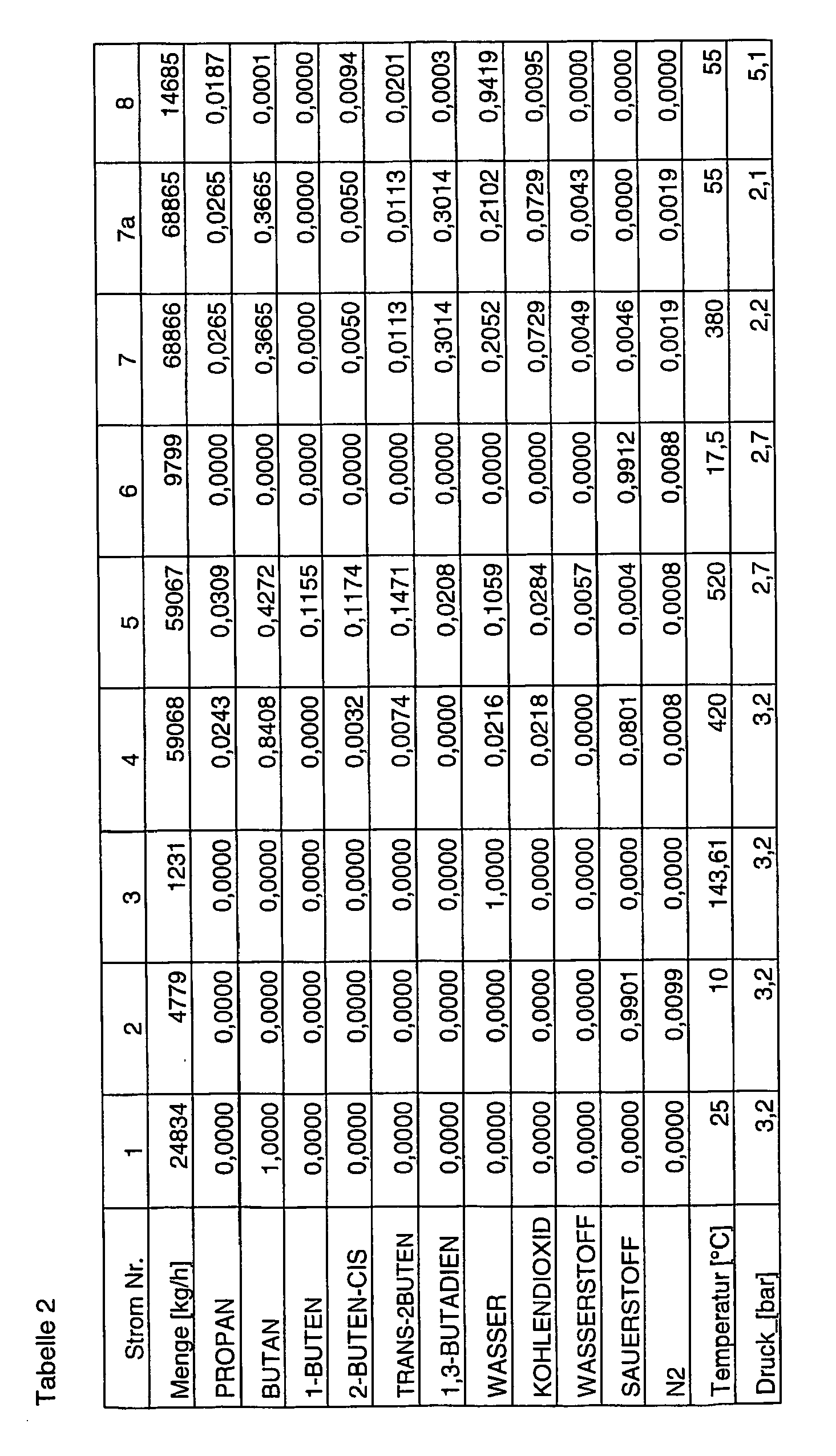


Claims (6)
- Verfahren zur Herstellung von Butadien aus n-Butan mit den SchrittenA) Bereitstellung eines n-Butan enthaltenden Einsatzgasstroms a;B) Einspeisung des n-Butan enthaltenden Einsatzgasstroms a in mindestens eine erste Dehydrierzone und nicht-oxidative, katalytische Dehydrierung von n-Butan, wobei ein Gasstrom b enthaltend n-Butan, 1-Buten, 2-Buten, Butadien, Wasserstoff, gegebenenfalls Kohlendioxid und gegebenenfalls Wasserdampf erhalten wird;C) Einspeisung des Gasstroms b und eines sauerstoffhaltigen Gases in mindestens eine zweite Dehydrierzone und oxidative Dehydrierung von 1-Buten und 2-Buten, wobei ein Gasstrom c enthaltend n-Butan, Butadien, Wasserstoff, Kohlendioxid und Wasserdampf erhalten wird,D) Kompression in mindestens einer ersten Kompressionsstufe und Abkühlung des Gasstroms c, wobei mindestens ein Kondensatstrom d1 enthaltend Wasser und ein Gasstrom d2 enthaltend n-Butan, Butadien, Wasserstoff, Kohlendioxid und Wasserdampf erhalten wird,E) Auftrennung des Gasstroms d2 durch Extraktivdestillation in einen im Wesentlichen aus Butadien bestehenden Produktstrom e1 und einen n-Butan, Wasserstoff, Kohlendioxid und Wasserdampf enthaltenden Strom e2,F) Kompression in mindestens einer weiteren Kompressionsstufe und Abkühlung des Gasstroms e2, wobei mindestens ein Kondensatstrom f1 enthaltend n-Butan und Wasser und ein Gasstrom f2 enthaltend n-Butan, Wasserstoff und Kohlendioxid erhalten werden,G) Abkühlung des Gasstroms f2, wobei ein Kondensatstrom g1 enthaltend n-Butan und ein Abgasstrom g2 enthaltend Kohlendioxid und Wasserstoff erhalten werden,H) Abtrennung von Wasser aus dem mindestens einen Kondensatstrom f1 und gegebenenfalls dem Kondensatstrom g1 durch Phasentrennung, wobei mindestens ein Rückführstrom h1 enthaltend n-Butan und mindestens ein Abwasserstrom h2 erhalten werden, und Rückführung des mindestens einen Rückführstroms h1 in die erste Dehydrierzone.
- Verfahren nach Anspruch 1, dadurch gekennzeichnet, dass die nicht-oxidative, katalytische Dehydrierung von n-Butan autotherm unter Einspeisung eines sauerstoffhaltigen Gases durchgeführt wird.
- Verfahren nach Anspruch 2, dadurch gekennzeichnet, dass als sauerstoffhaltiges Gas Luft eingespeist wird.
- Verfahren nach Anspruch 2, dadurch gekennzeichnet, dass als sauerstoffhaltiges Gas technisch reiner Sauerstoff eingespeist wird.
- Verfahren nach einer der Ansprüche 1 bis 4, dadurch gekennzeichnet, dass der n-Butan enthaltende Einsatzstrom a aus liquefied petroleum gas (LPG) gewonnen wird.
- Verfahren nach einem der Ansprüche 1 bis 5, dadurch gekennzeichnet, dass nach der Stufe C) der im Produktgas der oxidativen Dehydrierung verbliebene Sauerstoff entfernt wird, indem er katalytisch mit Wasserstoff umgesetzt wird.
Applications Claiming Priority (2)
| Application Number | Priority Date | Filing Date | Title |
|---|---|---|---|
| DE102004059356A DE102004059356A1 (de) | 2004-12-09 | 2004-12-09 | Verfahren zur Herstellung von Butadien aus n-Butan |
| PCT/EP2005/013105 WO2006061202A1 (de) | 2004-12-09 | 2005-12-07 | Verfahren zur herstellung von butadien aus n-butan |
Publications (2)
| Publication Number | Publication Date |
|---|---|
| EP1828080A1 EP1828080A1 (de) | 2007-09-05 |
| EP1828080B1 true EP1828080B1 (de) | 2011-02-23 |
Family
ID=36190767
Family Applications (1)
| Application Number | Title | Priority Date | Filing Date |
|---|---|---|---|
| EP05849467A Expired - Lifetime EP1828080B1 (de) | 2004-12-09 | 2005-12-07 | Verfahren zur herstellung von butadien aus n-butan |
Country Status (11)
| Country | Link |
|---|---|
| US (1) | US7435860B2 (de) |
| EP (1) | EP1828080B1 (de) |
| KR (1) | KR101265347B1 (de) |
| CN (1) | CN101076506B (de) |
| AT (1) | ATE499336T1 (de) |
| BR (1) | BRPI0518872A2 (de) |
| DE (2) | DE102004059356A1 (de) |
| EA (1) | EA012851B1 (de) |
| MY (1) | MY140931A (de) |
| TW (1) | TW200630332A (de) |
| WO (1) | WO2006061202A1 (de) |
Families Citing this family (25)
| Publication number | Priority date | Publication date | Assignee | Title |
|---|---|---|---|---|
| US7964765B2 (en) * | 2008-06-14 | 2011-06-21 | Lummus Technology Inc. | Styrene monomer process based on oxidative dehydrogenation of ethylbenzene using CO2 as a soft oxidant |
| US8258357B2 (en) * | 2009-03-25 | 2012-09-04 | Lummus Technology Inc. | Production of propylene from butane |
| US8420879B2 (en) | 2011-03-03 | 2013-04-16 | Basf Se | Process for workup of a stream comprising butene and/or butadiene |
| CN103502188B (zh) | 2011-03-03 | 2016-03-16 | 巴斯夫欧洲公司 | 包含丁烯和/或丁二烯的料流的后处理方法 |
| EP2711350B1 (de) * | 2011-05-19 | 2017-09-13 | Asahi Kasei Kabushiki Kaisha | Verfahren zur herstellung von 1,3-butadien |
| ITMI20112404A1 (it) * | 2011-12-28 | 2013-06-29 | Polimeri Europa Spa | Procedimento per la produzione di 1,3- butadiene |
| US9193647B2 (en) | 2012-01-30 | 2015-11-24 | Basf Se | Process for preparing butadiene and/or butenes from n-butane |
| JP6138161B2 (ja) * | 2012-01-30 | 2017-05-31 | ビーエーエスエフ ソシエタス・ヨーロピアBasf Se | n−ブタンからのブタジエンおよび/またはブテン類の製造方法 |
| IN2015DN00208A (de) | 2012-07-03 | 2015-06-12 | Basf Se | |
| US9352306B2 (en) | 2012-07-03 | 2016-05-31 | Basf Se | Catalyst and process for removing oxygen from hydrocarbon streams |
| EP2897927B1 (de) | 2012-09-20 | 2016-06-22 | Basf Se | Verfahren zur herstellung von butadien mit entfernung von sauerstoff aus c4-kohlenwasserstoffströmen |
| US9399606B2 (en) | 2012-12-06 | 2016-07-26 | Basf Se | Catalyst and process for the oxidative dehydrogenation of N-butenes to butadiene |
| US10144681B2 (en) | 2013-01-15 | 2018-12-04 | Basf Se | Process for the oxidative dehydrogenation of N-butenes to butadiene |
| KR20150105456A (ko) * | 2013-01-15 | 2015-09-16 | 바스프 에스이 | 산화성 탈수소화를 통해 n-부텐으로부터 1,3-부타디엔을 제조하는 방법 |
| EP2945923B1 (de) * | 2013-01-15 | 2017-03-15 | Basf Se | Verfahren zur oxidativen dehydrierung von n-butenen zu butadien |
| US9902669B2 (en) | 2013-03-07 | 2018-02-27 | Tpc Group Llc | Oxidative dehydrogenation process with hydrocarbon moderator gas and reduced nitrogen feed |
| CN104418691B (zh) * | 2013-08-19 | 2016-12-28 | 中国石化工程建设有限公司 | 一种氧化脱氢制丁二烯装置的废热回收方法 |
| US9611192B2 (en) | 2014-06-30 | 2017-04-04 | Uop Llc | Integration of N-C4/N-C4=/BD separation system for on-purpose butadiene synthesis |
| US10017431B2 (en) * | 2014-12-10 | 2018-07-10 | Lummus Technology Inc. | Process for co-producing C3 olefins, iC4 olefins, nC4 olefins and diolefins, and/or C5 olefins and diolefins |
| KR102050834B1 (ko) * | 2016-03-17 | 2019-12-02 | 주식회사 엘지화학 | 부타디엔의 제조 방법 |
| RU2696137C1 (ru) * | 2016-06-30 | 2019-07-31 | Юоп Ллк | Способ получения бутадиена путем окислительного дегидрирования с последующим прямым дегидрированием |
| DE102016224063A1 (de) | 2016-12-02 | 2018-06-07 | Thyssenkrupp Ag | Verfahren zur Herstellung von Butadien |
| CN107522586B (zh) * | 2017-09-12 | 2020-12-04 | 惠生工程(中国)有限公司 | 一种丁烯氧化脱氢制丁二烯工艺的炔烃处理方法 |
| JP6513278B1 (ja) | 2018-08-30 | 2019-05-15 | 株式会社Adeka | 組成物、これを含有する熱可塑性樹脂組成物およびその成形品 |
| JPWO2021044919A1 (de) * | 2019-09-02 | 2021-03-11 |
Family Cites Families (4)
| Publication number | Priority date | Publication date | Assignee | Title |
|---|---|---|---|---|
| JPS59167525A (ja) * | 1983-03-14 | 1984-09-21 | Japan Synthetic Rubber Co Ltd | 1,3−ブタジエンの製造方法 |
| IT1194350B (it) * | 1983-07-28 | 1988-09-14 | Snam Progetti | Procedimento per la produzione di butene-1 ad elevata purezza con basso consumo di energia |
| US4595788A (en) * | 1983-11-25 | 1986-06-17 | Nippon Zeon Co. Ltd. | Process for producing butadiene |
| MY135793A (en) * | 2002-07-12 | 2008-06-30 | Basf Ag | Method for the production of butadiene from n-butane |
-
2004
- 2004-12-09 DE DE102004059356A patent/DE102004059356A1/de not_active Withdrawn
-
2005
- 2005-12-07 EP EP05849467A patent/EP1828080B1/de not_active Expired - Lifetime
- 2005-12-07 BR BRPI0518872-5A patent/BRPI0518872A2/pt not_active IP Right Cessation
- 2005-12-07 CN CN2005800424474A patent/CN101076506B/zh not_active Expired - Fee Related
- 2005-12-07 AT AT05849467T patent/ATE499336T1/de active
- 2005-12-07 EA EA200701049A patent/EA012851B1/ru not_active IP Right Cessation
- 2005-12-07 WO PCT/EP2005/013105 patent/WO2006061202A1/de not_active Ceased
- 2005-12-07 US US11/721,240 patent/US7435860B2/en not_active Expired - Fee Related
- 2005-12-07 DE DE502005011011T patent/DE502005011011D1/de not_active Expired - Lifetime
- 2005-12-07 KR KR1020077012944A patent/KR101265347B1/ko not_active Expired - Fee Related
- 2005-12-08 MY MYPI20055754A patent/MY140931A/en unknown
- 2005-12-09 TW TW094143950A patent/TW200630332A/zh unknown
Also Published As
| Publication number | Publication date |
|---|---|
| MY140931A (en) | 2010-02-12 |
| US20080097133A1 (en) | 2008-04-24 |
| ATE499336T1 (de) | 2011-03-15 |
| KR101265347B1 (ko) | 2013-05-21 |
| EA012851B1 (ru) | 2009-12-30 |
| EP1828080A1 (de) | 2007-09-05 |
| DE102004059356A1 (de) | 2006-06-14 |
| WO2006061202A1 (de) | 2006-06-15 |
| KR20070085920A (ko) | 2007-08-27 |
| US7435860B2 (en) | 2008-10-14 |
| TW200630332A (en) | 2006-09-01 |
| CN101076506A (zh) | 2007-11-21 |
| BRPI0518872A2 (pt) | 2008-12-16 |
| EA200701049A1 (ru) | 2008-04-28 |
| DE502005011011D1 (de) | 2011-04-07 |
| CN101076506B (zh) | 2010-10-13 |
Similar Documents
| Publication | Publication Date | Title |
|---|---|---|
| EP1812365B1 (de) | Verfahren zur herstellung von butadien aus n-butan | |
| EP1828080B1 (de) | Verfahren zur herstellung von butadien aus n-butan | |
| EP1831134B1 (de) | Verfahren zur herstellung von butadien aus n-butan | |
| EP1708978B1 (de) | Verfahren zur herstellung von butadien | |
| EP1708977B1 (de) | Verfahren zur herstellung von butadien und 1-buten | |
| EP1682468B1 (de) | Verfahren zur herstellung von 1-buten | |
| EP1701928B1 (de) | Verfahren zur herstellung von butadien | |
| DE102005002127A1 (de) | Verfahren zur Herstellung von Butadien aus n-Butan | |
| EP2897927B1 (de) | Verfahren zur herstellung von butadien mit entfernung von sauerstoff aus c4-kohlenwasserstoffströmen | |
| EP2809633B1 (de) | Verfahren zur herstellung von butadien und/oder butenen aus n-butan | |
| EP1678105B1 (de) | Verfahren zur herstellung von 1-buten |
Legal Events
| Date | Code | Title | Description |
|---|---|---|---|
| PUAI | Public reference made under article 153(3) epc to a published international application that has entered the european phase |
Free format text: ORIGINAL CODE: 0009012 |
|
| 17P | Request for examination filed |
Effective date: 20070709 |
|
| AK | Designated contracting states |
Kind code of ref document: A1 Designated state(s): AT BE BG CH CY CZ DE DK EE ES FI FR GB GR HU IE IS IT LI LT LU LV MC NL PL PT RO SE SI SK TR |
|
| RAP1 | Party data changed (applicant data changed or rights of an application transferred) |
Owner name: BASF SE |
|
| DAX | Request for extension of the european patent (deleted) | ||
| GRAP | Despatch of communication of intention to grant a patent |
Free format text: ORIGINAL CODE: EPIDOSNIGR1 |
|
| GRAS | Grant fee paid |
Free format text: ORIGINAL CODE: EPIDOSNIGR3 |
|
| GRAA | (expected) grant |
Free format text: ORIGINAL CODE: 0009210 |
|
| AK | Designated contracting states |
Kind code of ref document: B1 Designated state(s): AT BE BG CH CY CZ DE DK EE ES FI FR GB GR HU IE IS IT LI LT LU LV MC NL PL PT RO SE SI SK TR |
|
| REG | Reference to a national code |
Ref country code: GB Ref legal event code: FG4D Free format text: NOT ENGLISH |
|
| REG | Reference to a national code |
Ref country code: CH Ref legal event code: EP |
|
| REG | Reference to a national code |
Ref country code: IE Ref legal event code: FG4D Free format text: LANGUAGE OF EP DOCUMENT: GERMAN |
|
| REF | Corresponds to: |
Ref document number: 502005011011 Country of ref document: DE Date of ref document: 20110407 Kind code of ref document: P |
|
| REG | Reference to a national code |
Ref country code: DE Ref legal event code: R096 Ref document number: 502005011011 Country of ref document: DE Effective date: 20110407 |
|
| REG | Reference to a national code |
Ref country code: NL Ref legal event code: T3 |
|
| LTIE | Lt: invalidation of european patent or patent extension |
Effective date: 20110223 |
|
| PG25 | Lapsed in a contracting state [announced via postgrant information from national office to epo] |
Ref country code: PT Free format text: LAPSE BECAUSE OF FAILURE TO SUBMIT A TRANSLATION OF THE DESCRIPTION OR TO PAY THE FEE WITHIN THE PRESCRIBED TIME-LIMIT Effective date: 20110623 Ref country code: LT Free format text: LAPSE BECAUSE OF FAILURE TO SUBMIT A TRANSLATION OF THE DESCRIPTION OR TO PAY THE FEE WITHIN THE PRESCRIBED TIME-LIMIT Effective date: 20110223 Ref country code: GR Free format text: LAPSE BECAUSE OF FAILURE TO SUBMIT A TRANSLATION OF THE DESCRIPTION OR TO PAY THE FEE WITHIN THE PRESCRIBED TIME-LIMIT Effective date: 20110524 Ref country code: ES Free format text: LAPSE BECAUSE OF FAILURE TO SUBMIT A TRANSLATION OF THE DESCRIPTION OR TO PAY THE FEE WITHIN THE PRESCRIBED TIME-LIMIT Effective date: 20110603 Ref country code: SE Free format text: LAPSE BECAUSE OF FAILURE TO SUBMIT A TRANSLATION OF THE DESCRIPTION OR TO PAY THE FEE WITHIN THE PRESCRIBED TIME-LIMIT Effective date: 20110223 Ref country code: LV Free format text: LAPSE BECAUSE OF FAILURE TO SUBMIT A TRANSLATION OF THE DESCRIPTION OR TO PAY THE FEE WITHIN THE PRESCRIBED TIME-LIMIT Effective date: 20110223 |
|
| PG25 | Lapsed in a contracting state [announced via postgrant information from national office to epo] |
Ref country code: BG Free format text: LAPSE BECAUSE OF FAILURE TO SUBMIT A TRANSLATION OF THE DESCRIPTION OR TO PAY THE FEE WITHIN THE PRESCRIBED TIME-LIMIT Effective date: 20110523 Ref country code: SI Free format text: LAPSE BECAUSE OF FAILURE TO SUBMIT A TRANSLATION OF THE DESCRIPTION OR TO PAY THE FEE WITHIN THE PRESCRIBED TIME-LIMIT Effective date: 20110223 Ref country code: FI Free format text: LAPSE BECAUSE OF FAILURE TO SUBMIT A TRANSLATION OF THE DESCRIPTION OR TO PAY THE FEE WITHIN THE PRESCRIBED TIME-LIMIT Effective date: 20110223 Ref country code: CY Free format text: LAPSE BECAUSE OF FAILURE TO SUBMIT A TRANSLATION OF THE DESCRIPTION OR TO PAY THE FEE WITHIN THE PRESCRIBED TIME-LIMIT Effective date: 20110223 |
|
| REG | Reference to a national code |
Ref country code: IE Ref legal event code: FD4D |
|
| PG25 | Lapsed in a contracting state [announced via postgrant information from national office to epo] |
Ref country code: DK Free format text: LAPSE BECAUSE OF FAILURE TO SUBMIT A TRANSLATION OF THE DESCRIPTION OR TO PAY THE FEE WITHIN THE PRESCRIBED TIME-LIMIT Effective date: 20110223 Ref country code: IE Free format text: LAPSE BECAUSE OF FAILURE TO SUBMIT A TRANSLATION OF THE DESCRIPTION OR TO PAY THE FEE WITHIN THE PRESCRIBED TIME-LIMIT Effective date: 20110223 Ref country code: EE Free format text: LAPSE BECAUSE OF FAILURE TO SUBMIT A TRANSLATION OF THE DESCRIPTION OR TO PAY THE FEE WITHIN THE PRESCRIBED TIME-LIMIT Effective date: 20110223 |
|
| PG25 | Lapsed in a contracting state [announced via postgrant information from national office to epo] |
Ref country code: SK Free format text: LAPSE BECAUSE OF FAILURE TO SUBMIT A TRANSLATION OF THE DESCRIPTION OR TO PAY THE FEE WITHIN THE PRESCRIBED TIME-LIMIT Effective date: 20110223 Ref country code: CZ Free format text: LAPSE BECAUSE OF FAILURE TO SUBMIT A TRANSLATION OF THE DESCRIPTION OR TO PAY THE FEE WITHIN THE PRESCRIBED TIME-LIMIT Effective date: 20110223 Ref country code: RO Free format text: LAPSE BECAUSE OF FAILURE TO SUBMIT A TRANSLATION OF THE DESCRIPTION OR TO PAY THE FEE WITHIN THE PRESCRIBED TIME-LIMIT Effective date: 20110223 |
|
| PLBE | No opposition filed within time limit |
Free format text: ORIGINAL CODE: 0009261 |
|
| STAA | Information on the status of an ep patent application or granted ep patent |
Free format text: STATUS: NO OPPOSITION FILED WITHIN TIME LIMIT |
|
| 26N | No opposition filed |
Effective date: 20111124 |
|
| PG25 | Lapsed in a contracting state [announced via postgrant information from national office to epo] |
Ref country code: PL Free format text: LAPSE BECAUSE OF FAILURE TO SUBMIT A TRANSLATION OF THE DESCRIPTION OR TO PAY THE FEE WITHIN THE PRESCRIBED TIME-LIMIT Effective date: 20110223 |
|
| REG | Reference to a national code |
Ref country code: DE Ref legal event code: R097 Ref document number: 502005011011 Country of ref document: DE Effective date: 20111124 |
|
| PG25 | Lapsed in a contracting state [announced via postgrant information from national office to epo] |
Ref country code: IT Free format text: LAPSE BECAUSE OF FAILURE TO SUBMIT A TRANSLATION OF THE DESCRIPTION OR TO PAY THE FEE WITHIN THE PRESCRIBED TIME-LIMIT Effective date: 20110223 |
|
| PG25 | Lapsed in a contracting state [announced via postgrant information from national office to epo] |
Ref country code: MC Free format text: LAPSE BECAUSE OF NON-PAYMENT OF DUE FEES Effective date: 20111231 |
|
| REG | Reference to a national code |
Ref country code: CH Ref legal event code: PL |
|
| GBPC | Gb: european patent ceased through non-payment of renewal fee |
Effective date: 20111207 |
|
| REG | Reference to a national code |
Ref country code: FR Ref legal event code: ST Effective date: 20120831 |
|
| PG25 | Lapsed in a contracting state [announced via postgrant information from national office to epo] |
Ref country code: LI Free format text: LAPSE BECAUSE OF NON-PAYMENT OF DUE FEES Effective date: 20111231 Ref country code: GB Free format text: LAPSE BECAUSE OF NON-PAYMENT OF DUE FEES Effective date: 20111207 Ref country code: CH Free format text: LAPSE BECAUSE OF NON-PAYMENT OF DUE FEES Effective date: 20111231 |
|
| REG | Reference to a national code |
Ref country code: AT Ref legal event code: MM01 Ref document number: 499336 Country of ref document: AT Kind code of ref document: T Effective date: 20111207 |
|
| PG25 | Lapsed in a contracting state [announced via postgrant information from national office to epo] |
Ref country code: FR Free format text: LAPSE BECAUSE OF NON-PAYMENT OF DUE FEES Effective date: 20120102 |
|
| PG25 | Lapsed in a contracting state [announced via postgrant information from national office to epo] |
Ref country code: LU Free format text: LAPSE BECAUSE OF NON-PAYMENT OF DUE FEES Effective date: 20111207 |
|
| PG25 | Lapsed in a contracting state [announced via postgrant information from national office to epo] |
Ref country code: AT Free format text: LAPSE BECAUSE OF NON-PAYMENT OF DUE FEES Effective date: 20111207 |
|
| PG25 | Lapsed in a contracting state [announced via postgrant information from national office to epo] |
Ref country code: IS Free format text: LAPSE BECAUSE OF FAILURE TO SUBMIT A TRANSLATION OF THE DESCRIPTION OR TO PAY THE FEE WITHIN THE PRESCRIBED TIME-LIMIT Effective date: 20110223 |
|
| PG25 | Lapsed in a contracting state [announced via postgrant information from national office to epo] |
Ref country code: TR Free format text: LAPSE BECAUSE OF FAILURE TO SUBMIT A TRANSLATION OF THE DESCRIPTION OR TO PAY THE FEE WITHIN THE PRESCRIBED TIME-LIMIT Effective date: 20110223 |
|
| PG25 | Lapsed in a contracting state [announced via postgrant information from national office to epo] |
Ref country code: HU Free format text: LAPSE BECAUSE OF FAILURE TO SUBMIT A TRANSLATION OF THE DESCRIPTION OR TO PAY THE FEE WITHIN THE PRESCRIBED TIME-LIMIT Effective date: 20110223 |
|
| PGFP | Annual fee paid to national office [announced via postgrant information from national office to epo] |
Ref country code: NL Payment date: 20161223 Year of fee payment: 12 |
|
| PGFP | Annual fee paid to national office [announced via postgrant information from national office to epo] |
Ref country code: BE Payment date: 20161222 Year of fee payment: 12 |
|
| PGFP | Annual fee paid to national office [announced via postgrant information from national office to epo] |
Ref country code: DE Payment date: 20170228 Year of fee payment: 12 |
|
| REG | Reference to a national code |
Ref country code: DE Ref legal event code: R119 Ref document number: 502005011011 Country of ref document: DE |
|
| REG | Reference to a national code |
Ref country code: NL Ref legal event code: MM Effective date: 20180101 |
|
| PG25 | Lapsed in a contracting state [announced via postgrant information from national office to epo] |
Ref country code: NL Free format text: LAPSE BECAUSE OF NON-PAYMENT OF DUE FEES Effective date: 20180101 |
|
| REG | Reference to a national code |
Ref country code: BE Ref legal event code: MM Effective date: 20171231 |
|
| PG25 | Lapsed in a contracting state [announced via postgrant information from national office to epo] |
Ref country code: DE Free format text: LAPSE BECAUSE OF NON-PAYMENT OF DUE FEES Effective date: 20180703 |
|
| PG25 | Lapsed in a contracting state [announced via postgrant information from national office to epo] |
Ref country code: BE Free format text: LAPSE BECAUSE OF NON-PAYMENT OF DUE FEES Effective date: 20171231 |