EP1828541B1 - Verbrennungsmotor mit mobiler brennkammer - Google Patents
Verbrennungsmotor mit mobiler brennkammer Download PDFInfo
- Publication number
- EP1828541B1 EP1828541B1 EP05856243A EP05856243A EP1828541B1 EP 1828541 B1 EP1828541 B1 EP 1828541B1 EP 05856243 A EP05856243 A EP 05856243A EP 05856243 A EP05856243 A EP 05856243A EP 1828541 B1 EP1828541 B1 EP 1828541B1
- Authority
- EP
- European Patent Office
- Prior art keywords
- rotor
- mobile
- chamber
- engine
- chamber element
- Prior art date
- Legal status (The legal status is an assumption and is not a legal conclusion. Google has not performed a legal analysis and makes no representation as to the accuracy of the status listed.)
- Expired - Lifetime
Links
Images


Classifications
-
- F—MECHANICAL ENGINEERING; LIGHTING; HEATING; WEAPONS; BLASTING
- F01—MACHINES OR ENGINES IN GENERAL; ENGINE PLANTS IN GENERAL; STEAM ENGINES
- F01C—ROTARY-PISTON OR OSCILLATING-PISTON MACHINES OR ENGINES
- F01C1/00—Rotary-piston machines or engines
- F01C1/30—Rotary-piston machines or engines having the characteristics covered by two or more groups F01C1/02, F01C1/08, F01C1/22, F01C1/24 or having the characteristics covered by one of these groups together with some other type of movement between co-operating members
- F01C1/34—Rotary-piston machines or engines having the characteristics covered by two or more groups F01C1/02, F01C1/08, F01C1/22, F01C1/24 or having the characteristics covered by one of these groups together with some other type of movement between co-operating members having the movement defined in group F01C1/08 or F01C1/22 and relative reciprocation between the co-operating members
-
- F—MECHANICAL ENGINEERING; LIGHTING; HEATING; WEAPONS; BLASTING
- F01—MACHINES OR ENGINES IN GENERAL; ENGINE PLANTS IN GENERAL; STEAM ENGINES
- F01C—ROTARY-PISTON OR OSCILLATING-PISTON MACHINES OR ENGINES
- F01C1/00—Rotary-piston machines or engines
- F01C1/30—Rotary-piston machines or engines having the characteristics covered by two or more groups F01C1/02, F01C1/08, F01C1/22, F01C1/24 or having the characteristics covered by one of these groups together with some other type of movement between co-operating members
- F01C1/34—Rotary-piston machines or engines having the characteristics covered by two or more groups F01C1/02, F01C1/08, F01C1/22, F01C1/24 or having the characteristics covered by one of these groups together with some other type of movement between co-operating members having the movement defined in group F01C1/08 or F01C1/22 and relative reciprocation between the co-operating members
- F01C1/344—Rotary-piston machines or engines having the characteristics covered by two or more groups F01C1/02, F01C1/08, F01C1/22, F01C1/24 or having the characteristics covered by one of these groups together with some other type of movement between co-operating members having the movement defined in group F01C1/08 or F01C1/22 and relative reciprocation between the co-operating members with vanes reciprocating with respect to the inner member
- F01C1/3448—Rotary-piston machines or engines having the characteristics covered by two or more groups F01C1/02, F01C1/08, F01C1/22, F01C1/24 or having the characteristics covered by one of these groups together with some other type of movement between co-operating members having the movement defined in group F01C1/08 or F01C1/22 and relative reciprocation between the co-operating members with vanes reciprocating with respect to the inner member with axially movable vanes
Definitions
- the present invention concerns an internal combustion engine, comprising at least one mobile chamber element which can have the combined functions of a compression chamber, a combustion chamber, a valve, a member defining the portions with cyclically variable volume, a device for translating compressed gases.
- such an element for an internal combustion engine is capable of defining regions with cyclically variable volume during the rotation of the toroidal element it is connected to.
- such an element for an internal combustion engine includes, or consists of, a single body and accessory members (such as sealing members, motion guiding members, mixture igniting members, and so on).
- such an element for an internal combustion engine includes, or consists of, several parts assembled so as to be relatively movable or stationary, and accessory members, if any.
- such an element for an internal combustion engine is radially slidable (for accomplishing its task) relative to the toroidal element inside the casing.
- such an element for an internal combustion engine is laterally slidable relative to the toroidal element.
- such an element for an internal combustion engine is capable of effecting one or more composite movements radially and/or laterally relative to the toroidal element.
- such an element for an internal combustion engine is pivotally connected to the toroidal element and is angularly movable, or also angularly movable, relative to the toroidal element.
- such an element for an internal combustion engine includes a structure or a fitting capable of varying the internal volumetric capacity thereof.
- such an element for an internal combustion engine is connected to a device provided on the casing, e.g. a guide or the like, conditioning its movement relative to the torus or other rotating element during rotation.
- a rotor or toroidal element 14 is located within a housing or casing 12 and adheres thereto at some regions, whereas at other regions, corresponding to angular portions of the torus rotation, i.e. corresponding to one or more predetermined circular sectors of torus 14, the rotor is spaced apart from said casing 12 thereby defining hollow chambers.
- rotor 14 of substantially toroidal shape, is housed within an annular cavity formed inside a housing or casing 12.
- the shape of the annular cavity does not exactly correspond to the shape of rotor 14, but it has a greater cross-sectional size in certain regions so as to define said hollow chambers, which are defined by parts of the walls of rotor 14, of the annular casing cavity and of the moving chamber elements disclosed hereinafter.
- Said hollow chambers can be e.g. symmetrically arranged internally and externally of torus 14, relative to rotation axis A, or to the left or the right of the torus, as well as internally and on one side, or even externally and on one side or even internally, externally, on one side and on the opposite side at the same time. This will become more apparent from the following description of one of the possible embodiments of the device.
- Element 10 is a single-piece element or is possibly made of multiple pieces, and it must be capable of adhering to the surfaces outside torus 14 and the cavity provided therein, so as to allow a radial, a lateral or a combined movement of said elements.
- torus 14 will result, through the displacement of said elements, in the creation of two or more chambers with cyclically variable volume, which chambers are formed by the internal surface of casing 12, the external surface of torus 14 and both the internal and the external surfaces of one or more elements 10.
- the latter are referred to, in the present description, as "mobile chamber elements 10".
- Said mobile chamber elements 10, during rotation of torus 14 about axis A move along the surface of casing 12 according to a positively actuated motion, which may be natural or also induced by a fixed guide and in any case is such as to allow the correct element operation.
- the radially innermost or outermost walls of the casing chambers, where rotor 14 moves act as cam profiles
- mobile chamber elements 10 act as the driven elements of a cam-operated system.
- Mobile chambers two in the present description, but whose number could even be different, form the element allowing first gas suction, then gas compression, the translation of the compressed gas to a chamber outside torus 14, on the side opposed to said chamber. There, gas ignition and then gas burst will take place, and the gases, by pressing against "mobile chamber” 10, will make torus 14 rotate about its axis A, while allowing at the same time execution of the four strokes of a four-stroke engine in the chambers or portions thereof defined as disclosed above.
- Reference numeral 34 in the Figures denotes an ignition device, such as a spark plug, capable of causing ignition of the combustible gas mixture present in a suitable region of the annular cavity inside casing 12.
- the combustible gas mixture is ignited by a spark plug 34 when it is compressed in a hollow chamber.
- FIG. 1 to 10 laterally slidable chambers 10 ( Figs. 1 to 10 ), i.e. chambers slidable e.g. in a direction parallel to rotation axis A of rotor 14, or radially slidable chambers ( Fig. 11 ) or yet pivotally mounted chambers ( Fig. 12 , i.e. chambers which are fastened to rotor 14 by means of a pivot pin 34, so that they can radially oscillate).
- Figs. 1 to 10 i.e. chambers slidable e.g. in a direction parallel to rotation axis A of rotor 14, or radially slidable chambers ( Fig. 11 ) or yet pivotally mounted chambers ( Fig. 12 , i.e. chambers which are fastened to rotor 14 by means of a pivot pin 34, so that they can radially oscillate).
- All chambers have the functions of "piston”, intended as a pushing member, "valve”, due to the possibility of opening and closing internal flow paths, compression chamber, or at least a part thereof, combustion chamber, or at least a part thereof, and basic member for translating gases relative to a toroidal element 14 forming the basic engine structure.
- a mobile chamber element 10 defines, together with the walls of a mobile chamber in the annular casing cavity, a chamber with increasing variable volume, and causes suction of air or a gas mixture from suction duct IN (legend ASP in Fig. 11 ).
- suction When performing suction, rotor 14 closes a port in the passage inside element 10 itself, thereby preventing, apart from leaks, important gas flows from upstream to downstream the concerned element 10 through internal passage 28 thereof.
- mobile chamber element 10 and the walls of the annular cavity form a chamber with progressively decreasing variable volume and compress the sucked gases (legend COMP in Fig. 11 ).
- mobile chamber element 10 is progressively spaced apart from the walls of the annular cavity, in radial direction towards the outside of the same annular chamber, as long as both end ports of internal passage 28 begin to open: thus, the sucked gases is allowed to flow, at least in part, from the hollow chamber located on the radially internal side of rotor 14 to another hollow chamber located on the radially external side of rotor 14 (legend ESP in Fig. 11 ).
- mobile chamber element 10 is radially displaced towards the outside of rotor 14, so that the latter closes one port in passage 28, the passage of combustible gases between hollow chamber COMP and hollow chamber ESP is thereby prevented.
- ignition spark plug 34 ignites the combustible gas mixture present in hollow chamber ESP and causes gas explosion.
- the burnt gas mixture expands in chamber ESP and provides further energy for the rotation of rotor 14.
- rotor 14 pushes the combusted gases through annular cavity portion SCAR and then through exhaust port OUT.
- the combustion cycle just disclosed is repeated substantially identically for the other mobile chamber elements 10 of the rotor.
- each chamber will be, starting from the suction phase: defining a cyclically variable space formed by the internal surface of casing 12, by the external surface of torus 14 and by mobile chamber 10 or by the portion thereof extending into said space.
- the chamber On its rear side, with reference to the rotation direction, the chamber makes the hollow volume of the structure increase and hence provides for a natural suction.
- the front portion with reference to the rotation direction, compresses the gases sucked because of the passage of previous moving chamber 10. Hence, for the whole duration of that phase, suction and compression take place simultaneously.
- chamber 10 located on the opposite side of the first one will be effecting the pushing or explosion phase on its rear side and will be effecting the burnt gas exhaust phase on the other side.
- the engine could be defined a four-stroke 4/4 engine, this denoting that the four strokes of the Otto cycle simultaneously occur, like in a conventional four-cylinder engine with cranks arranged at 180°.
- the solution allows constructing an engine formed by a casing (or housing) 12 containing a toroidal ring 14 and two mobile chambers 10, in the whole, three mobile members (besides, of course, the sealing members, the electrical fittings and so on).
- Rotor 14 may be connected for instance to an output shaft (not shown), by which the motive power generated by the engine can be transferred to the outside.
- reference numeral 30 denotes a sealing member, capable of limiting leakage of fluids present inside the annular cavity between mobile chamber element 10 and the walls of the same annular cavity.
- a sealing member 30 may be for instance a compression ring, a set of compression rings or one or more gaskets provided around and outside mobile chamber element 10.
- the essential components of said kind of engine are the mobile chambers 10 determining the cyclical variability of the internal chambers and the fluid passage from one side to the other of the torus and through the chamber structure.
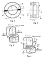
- Fig. 3 is a view of the part facing the viewer of an engine according to the present invention.
- Fig. 4 is a view of the opposite part, in which:
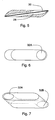
- Fig. 5 is a longitudinal cross-sectional view of a mobile chamber 10, where:
- Fig. 6 is a plan view of mobile chamber 10 and Fig. 7 is a three-dimensional view thereof, where 32 denotes the outlet point of the internal duct. Figs 8, 9 and 10 show the same elements in different positions.
- Fig. 11 is a plan view of a radial engine, with mobile chambers 10' radially slidable in their seats provided in rotor 14.
- Fig. 12 is a plan view of a radial engine, with mobile chambers 10" angularly movable about a pivot point 34; the other reference symbols are as already described.
Landscapes
- Engineering & Computer Science (AREA)
- Mechanical Engineering (AREA)
- General Engineering & Computer Science (AREA)
- Output Control And Ontrol Of Special Type Engine (AREA)
- Cylinder Crankcases Of Internal Combustion Engines (AREA)
Claims (14)
- Ein Verbrennungsmotor, umfassend:- ein Gehäuse (12), in welchem ein im Wesentlichen ringförmiger Hohlraum ausgebildet ist;- einen im Wesentlichen ringförmigen Rotor (14), welcher innerhalb des ringförmigen Hohlraums aufgenommen ist;- wenigstens ein mobiles Kammerelement (10), welches an dem Rotor (14) festgelegt ist;dadurch gekennzeichnet, dass zumindest innerhalb eines Teils der wenigstens einen Hohlkammer das wenigstens eine, mobile Kammerelement (10) wenigstens entlang der Drehachse des Rotors (14) selbst verschiebbar ist, während es die Wände des selben ringförmigen Hohlraums berührt und dadurch auf fluiddichte Weise den Bereich der Hohlkammer vor dem mobilen Kammerlement (10) von dem Bereich der Hohlkammer hinter dem mobilen Kammerelement (10) trennt.
- Der Motor, wie im Anspruch 1 beansprucht, umfassend eine Mehrzahl von Hohlkammern.
- Der Motor, wie im Anspruch 1 oder 2 beansprucht, umfassend eine Mehrzahl von mobilen Kammerelementen (10).
- Der Motor, wie in einem oder mehreren der vorhergehenden Ansprüche beansprucht, wobei das wenigstens eine, mobile Kammerelement (10) entsprechend der wenigstens einen, mobilen Kammer in wenigstens Richtung entlang der Drehachse des Rotors verschiebbar ist und entlang der wenigstens einen Richtung entlang der Drehachse des Rotors eine Größe aufweist, die substantiell größer ist als die Querschnittsgröße des Rotors (14).
- Der Motor, wie in einem oder mehreren der vorhergehenden Ansprüche beansprucht, wobei das wenigstens eine, mobile Kammerelement (10) eine Passage (28) aufweist, die sich durch das mobile Kammerlement hindurch von einem Ende bis zu dem anderen erstreckt und in zwei Mündungen (32A, 32B) endet, und wobei in wenigstens einem Betriebszustand:- eine Mündung (32A) entweder durch den Rotor oder das äußere Gehäuse verschlossen ist, wodurch in dem Hohlkammerbereich vor dem mobilen Kammerelement (10) vorliegende Fluide substantiell davon abgehalten werden, in den Hohlkammerbereich hinter dem mobilen Kammerelement (10) zu strömen, oder, umgekehrt, in dem Hohlkammerbereich hinter dem mobilen Kammerelement (10) vorliegende Fluide substantiell davon abgehalten werden, in den Hohlkammerbereich vor dem mobilen Kammerelement (10) zu strömen; und- die andere Mündung (32B) offen ist, wodurch entweder in dem Hohlkammerbereich hinter dem mobilen Kammerelement (10) oder in dem Hohlkammerbereich vor dem mobilen Kammerelement (10) vorliegende Fluide in besagte Mündung gelangen können.
- Der Motor, wie in einem oder mehreren der vorhergehenden Ansprüche beansprucht, wobei das wenigstens eine, mobile Kammerelement (10) eine Passage (28) aufweist, die sich durch das mobile Kammerlement hindurch von einem Ende bis zu dem gegenüberliegenden erstreckt und in zwei Mündungen (32A, 32B) endet, und wobei in wenigstens einem Betriebszustand beide Mündungen (32A) offen sind, so dass es in dem Hohlkammerbereich hinter dem mobilen Kammerelement (10) vorliegenden Fluiden möglich ist, in den Hohlkammerbereich vor dem mobilen Kammerelement (10) zu strömen oder, umgekehrt, wobei es in dem Hohlkammerbereich vor dem mobilen Kammerelement (10) vorliegenden Fluiden möglich ist, in den Hohlkammerbereich hinter dem mobilen Kammerelement (10) zu strömen.
- Der Motor, wie in einem oder mehreren der vorhergehenden Ansprüche beansprucht, wobei das wenigstens eine, mobile Kammerelement (10) an dem Rotor (14) festgelegt ist, derart, dass es gegenüber dem Rotor zumindest parallel verschiebbar ist, vorzugsweise in einer Richtung entlang der Drehachse des Rotors.
- Der Motor, wie in einem oder mehreren der vorhergehenden Ansprüche beansprucht, wobei das wenigstens eine, mobile Kammerelement (10) an dem Rotor (14) festgelegt ist, derart, dass es gegenüber jenem zumindest verdrehbar ist, vorzugsweise durch Verschieben wenigstens eines Teils desselben Elements (10) in einer Richtung entlang der Drehachse des Rotors (14).
- Der Motor, wie in einem oder mehreren der vorhergehenden Ansprüche beansprucht, wobei die Verschiebungen des wenigstens einen, mobilen Kammerelements (10) durch die Wände der ringförmigen Kammer und/oder durch andere Gehäusebereiche hervorgerufen werden.
- Der Motor, wie im Anspruch 9 beansprucht, wobei die Wände der ringförmigen Kammer und/oder die anderen Gehäusebereiche derart angeordnet sind, um die Verschiebungen des wenigstens einen, mobilen Kammerelements (10) hervorzurufen, indem sie letzteres im Wesentlichen wie ein Nockenprofil stoßen.
- Der Motor, wie in einem oder mehreren der vorhergehenden Ansprüche beansprucht, wobei das Gehäuse, der Rotor (14) und das wenigstens eine, mobile Kammerelement (10) derart ausgelegt sind, dass sie wenigstens eine Kammer mit einem variablen Volumen bilden, welches mit der Rotation des Rotors (14) zunimmt sowie derart ausgebildet ist, dass ein Fluid in das Gehäuse gesaugt wird.
- Der Motor, wie in einem oder mehreren der vorhergehenden Ansprüche beansprucht, wobei das Gehäuse, der Rotor (14) und das wenigstens eine, mobile Kammerelement (10) derart ausgelegt sind, dass sie wenigstens eine Kammer mit einem variablen Volumen bilden, welches mit der Rotation des Rotors (14) abnimmt sowie derart ausgebildet ist, dass ein innerhalb des Gehäuses vorhandenes Fluid komprimiert wird.
- Der Motor, wie in einem oder mehreren der vorhergehenden Ansprüche beansprucht, umfassend ein Zündgerät (34) zum Zünden eines innerhalb des Gehäuses vorhandenen Fluids.
- Ein Verbrennungsmotor, umfassend:- ein Gehäuse (12), in welchem ein im Wesentlichen ringförmiger Hohlraum ausgebildet ist;- einen im Wesentlichen ringförmigen Rotor (14), welcher innerhalb des ringförmigen Hohlraums aufgenommen ist;- wenigstens ein mobiles Kammerelement (10), welches an dem Rotor (14) festgelegt ist;wobei der ringförmige Hohlraum, zumindest in einem Teil desselben, Querschnitte, welche größer sind als Querschnitte des Rotors (14), um dadurch wenigstens eine Hohlkammer (16, 18) zu definieren;
dadurch gekennzeichnet, dass zumindest innerhalb eines Teils der wenigstens einen Hohlkammer das wenigstens eine, mobile Kammerelement (10) an dem Rotor (14) festgelegt ist, um zumindest jenem gegenüber drehbar zu sein, vorzugsweise durch Verschieben wenigstens eines Teils des selben Elements (10) in einer Richtung quer zu dem ringförmigen Körper des Rotors (14), während jenes die Wände des selben ringförmigen Hohlraums berührt und dadurch auf fluiddichte Weise den Bereich der Hohlkammer vor dem mobilen Kammerlement (10) von dem Bereich der Hohlkammer hinter dem mobilen Kammerelement (10) trennt.
Applications Claiming Priority (2)
| Application Number | Priority Date | Filing Date | Title |
|---|---|---|---|
| IT000623A ITRM20040623A1 (it) | 2004-12-20 | 2004-12-20 | Camera mobile. |
| PCT/IB2005/003828 WO2006072820A2 (en) | 2004-12-20 | 2005-12-20 | Ic engine with mobile combustion chamber |
Publications (2)
| Publication Number | Publication Date |
|---|---|
| EP1828541A2 EP1828541A2 (de) | 2007-09-05 |
| EP1828541B1 true EP1828541B1 (de) | 2013-02-13 |
Family
ID=36586127
Family Applications (1)
| Application Number | Title | Priority Date | Filing Date |
|---|---|---|---|
| EP05856243A Expired - Lifetime EP1828541B1 (de) | 2004-12-20 | 2005-12-20 | Verbrennungsmotor mit mobiler brennkammer |
Country Status (5)
| Country | Link |
|---|---|
| US (1) | US20100012078A1 (de) |
| EP (1) | EP1828541B1 (de) |
| ES (1) | ES2406961T3 (de) |
| IT (1) | ITRM20040623A1 (de) |
| WO (1) | WO2006072820A2 (de) |
Families Citing this family (5)
| Publication number | Priority date | Publication date | Assignee | Title |
|---|---|---|---|---|
| KR20080033482A (ko) * | 2005-08-01 | 2008-04-16 | 사바스 사바키스 | 내연 기관 |
| US20090308342A1 (en) * | 2006-12-19 | 2009-12-17 | Net-New Engines Technologies Ltd. | Rotary engine with cylinders of different design and volume |
| GB2493061A (en) | 2011-07-15 | 2013-01-23 | Ecomotors Internat Inc | Opposed piston engine with toroidal combustion chamber |
| ITRM20120438A1 (it) * | 2012-09-14 | 2014-03-15 | Romano Murri | Motore rotativo con camere di compressione a volume variabile |
| RU2727739C2 (ru) * | 2017-12-15 | 2020-07-23 | Альмир Вагисович Адельшин | Способ работы двигателя внутреннего сгорания "усовершенствованный агрегатно-фазовый термодинамический цикл а. адельшина для двс" и двигатель, работающий по данному циклу |
Family Cites Families (22)
| Publication number | Priority date | Publication date | Assignee | Title |
|---|---|---|---|---|
| US980506A (en) * | 1910-02-12 | 1911-01-03 | Eric Harald Ewertz | Rotary internal-combustion engine. |
| US1116781A (en) * | 1913-09-25 | 1914-11-10 | Warner A Olsen | Internal-combustion engine. |
| US1427692A (en) * | 1919-09-26 | 1922-08-29 | Thomas C Mahon | Internal-combustion rotary engine |
| US2071799A (en) * | 1934-09-08 | 1937-02-23 | Mabille Raoul | Rotary engine |
| US2298525A (en) * | 1941-10-08 | 1942-10-13 | Arthur M Briggs | Rotary internal combustion engine |
| US3181509A (en) * | 1963-01-29 | 1965-05-04 | Lewis B Simon | Sealing means for rotary engines |
| US3181510A (en) * | 1963-03-01 | 1965-05-04 | Robert W Hovey | Rotary vane device |
| US3572985A (en) * | 1968-03-19 | 1971-03-30 | Franz Joachim Runge | Rotary piston machine |
| US3682143A (en) * | 1970-06-03 | 1972-08-08 | Leas Brothers Dev Corp | Cylindrical rotor internal combustion engine |
| GB1296769A (de) * | 1970-11-18 | 1972-11-15 | ||
| BE793039A (fr) * | 1971-12-21 | 1973-04-16 | Fischer Arno | Machine a piston rotatif |
| US4033299A (en) * | 1975-01-22 | 1977-07-05 | Manzoni Sergio C | Rotary engine |
| DE2851346A1 (de) * | 1978-11-28 | 1980-05-29 | Juergen Kuechler | Brennkammerturbine |
| JPS55104503A (en) * | 1979-02-02 | 1980-08-11 | Yoshiro Hosoyama | Rotary engine |
| JPS61160527A (ja) * | 1985-01-07 | 1986-07-21 | Fumio Ueda | 回転動力装置 |
| GB2183732A (en) * | 1985-12-06 | 1987-06-10 | Charles Sejbl | Sinusoidal pump/motor |
| CH673509A5 (de) * | 1986-10-27 | 1990-03-15 | Notron Engineering Ag | |
| CA1304692C (en) * | 1987-05-08 | 1992-07-07 | Milos Vujic | Rotary internal combustion engine |
| AU4938693A (en) * | 1992-08-19 | 1994-03-15 | Brian W. Cherry | Axial vane rotary engine with rounded vanes |
| US5555866A (en) * | 1995-06-06 | 1996-09-17 | Wilson; Jack A. | Rotary engine |
| ITRM960802A1 (it) * | 1996-11-22 | 1997-02-22 | Romano Murri | Ciclo di funzionamento e motore m.a.r.z.i.a. motore endotermico appli cato a rotore e zone di interscambio |
| FI110807B (fi) * | 2001-01-30 | 2003-03-31 | Tapio Viitamaeki | Pyörivä polttomoottori |
-
2004
- 2004-12-20 IT IT000623A patent/ITRM20040623A1/it unknown
-
2005
- 2005-12-20 ES ES05856243T patent/ES2406961T3/es not_active Expired - Lifetime
- 2005-12-20 WO PCT/IB2005/003828 patent/WO2006072820A2/en not_active Ceased
- 2005-12-20 US US11/721,918 patent/US20100012078A1/en not_active Abandoned
- 2005-12-20 EP EP05856243A patent/EP1828541B1/de not_active Expired - Lifetime
Also Published As
| Publication number | Publication date |
|---|---|
| WO2006072820A9 (en) | 2006-10-12 |
| ITRM20040623A1 (it) | 2005-03-20 |
| WO2006072820A3 (en) | 2006-08-31 |
| ES2406961T3 (es) | 2013-06-10 |
| EP1828541A2 (de) | 2007-09-05 |
| WO2006072820A2 (en) | 2006-07-13 |
| US20100012078A1 (en) | 2010-01-21 |
Similar Documents
| Publication | Publication Date | Title |
|---|---|---|
| US7117839B2 (en) | Multi-stage modular rotary internal combustion engine | |
| WO2012057838A2 (en) | Rotary valve continuous flow expansible chamber dynamic and positive displacement rotary devices | |
| WO2014149445A1 (en) | Rotary internal combustion engine | |
| RU2633743C2 (ru) | Камера сгорания постоянного объема для авиационного турбинного двигателя, содержащая впускной/выпускной клапан, имеющий сферическую заглушку | |
| JPH062559A (ja) | ロータリエンジン | |
| EP1828541B1 (de) | Verbrennungsmotor mit mobiler brennkammer | |
| US7140853B2 (en) | Axial vane rotary device | |
| RU2351780C1 (ru) | Роторно-поршневой двигатель внутреннего сгорания | |
| EP1366275B1 (de) | Rotationskolbenmotor mit innerer verbrennung | |
| US4422419A (en) | Rotary internal combustion engine | |
| RU2720879C1 (ru) | Роторно-поршневой двигатель внутреннего сгорания | |
| US5555866A (en) | Rotary engine | |
| CN100410493C (zh) | 适于作为压缩机,马达,泵和内燃机的设备 | |
| EP0046586B1 (de) | Brennkraftmaschine mit innerer Verbrennung | |
| US4432314A (en) | Internal combustion engine | |
| US20170089201A1 (en) | Hybrid pneumatic / internal combustion rotary engine | |
| EP2808484A1 (de) | Viertakt-Rotationskolbenmotor | |
| RU2427716C1 (ru) | Роторно-поршневой двигатель внутреннего сгорания | |
| RU2477376C2 (ru) | Двигатель внутреннего сгорания: 5-тактный роторный двигатель с вращающимися запорными элементами, раздельными секциями сжатия и расширения рабочего тела и обособленными камерами сгорания неизменного объема | |
| RU2377426C2 (ru) | Роторный двигатель | |
| KR20160129780A (ko) | 이중터빈 내연기관 | |
| JPS5849692B2 (ja) | ナイネンキカン | |
| RU2805946C1 (ru) | Роторно-поршневой двигатель внутреннего сгорания | |
| CN109826703B (zh) | 一种转臂发动机和发动机组 | |
| RU2170354C1 (ru) | Роторно-поршневой двигатель внутреннего сгорания |
Legal Events
| Date | Code | Title | Description |
|---|---|---|---|
| PUAI | Public reference made under article 153(3) epc to a published international application that has entered the european phase |
Free format text: ORIGINAL CODE: 0009012 |
|
| 17P | Request for examination filed |
Effective date: 20070627 |
|
| AK | Designated contracting states |
Kind code of ref document: A2 Designated state(s): AT BE BG CH CY CZ DE DK EE ES FI FR GB GR HU IE IS IT LI LT LU LV MC NL PL PT RO SE SI SK TR |
|
| DAX | Request for extension of the european patent (deleted) | ||
| RAP1 | Party data changed (applicant data changed or rights of an application transferred) |
Owner name: GENOMNIA S.R.L. |
|
| RAP1 | Party data changed (applicant data changed or rights of an application transferred) |
Owner name: GENOMNIA S.R.L. |
|
| GRAP | Despatch of communication of intention to grant a patent |
Free format text: ORIGINAL CODE: EPIDOSNIGR1 |
|
| GRAS | Grant fee paid |
Free format text: ORIGINAL CODE: EPIDOSNIGR3 |
|
| GRAA | (expected) grant |
Free format text: ORIGINAL CODE: 0009210 |
|
| AK | Designated contracting states |
Kind code of ref document: B1 Designated state(s): AT BE BG CH CY CZ DE DK EE ES FI FR GB GR HU IE IS IT LI LT LU LV MC NL PL PT RO SE SI SK TR |
|
| REG | Reference to a national code |
Ref country code: GB Ref legal event code: FG4D |
|
| REG | Reference to a national code |
Ref country code: AT Ref legal event code: REF Ref document number: 596616 Country of ref document: AT Kind code of ref document: T Effective date: 20130215 |
|
| REG | Reference to a national code |
Ref country code: IE Ref legal event code: FG4D |
|
| REG | Reference to a national code |
Ref country code: DE Ref legal event code: R096 Ref document number: 602005038168 Country of ref document: DE Effective date: 20130411 |
|
| REG | Reference to a national code |
Ref country code: ES Ref legal event code: FG2A Ref document number: 2406961 Country of ref document: ES Kind code of ref document: T3 Effective date: 20130610 |
|
| REG | Reference to a national code |
Ref country code: AT Ref legal event code: MK05 Ref document number: 596616 Country of ref document: AT Kind code of ref document: T Effective date: 20130213 |
|
| REG | Reference to a national code |
Ref country code: NL Ref legal event code: VDEP Effective date: 20130213 |
|
| REG | Reference to a national code |
Ref country code: LT Ref legal event code: MG4D |
|
| PG25 | Lapsed in a contracting state [announced via postgrant information from national office to epo] |
Ref country code: SE Free format text: LAPSE BECAUSE OF FAILURE TO SUBMIT A TRANSLATION OF THE DESCRIPTION OR TO PAY THE FEE WITHIN THE PRESCRIBED TIME-LIMIT Effective date: 20130213 Ref country code: LT Free format text: LAPSE BECAUSE OF FAILURE TO SUBMIT A TRANSLATION OF THE DESCRIPTION OR TO PAY THE FEE WITHIN THE PRESCRIBED TIME-LIMIT Effective date: 20130213 Ref country code: AT Free format text: LAPSE BECAUSE OF FAILURE TO SUBMIT A TRANSLATION OF THE DESCRIPTION OR TO PAY THE FEE WITHIN THE PRESCRIBED TIME-LIMIT Effective date: 20130213 Ref country code: IS Free format text: LAPSE BECAUSE OF FAILURE TO SUBMIT A TRANSLATION OF THE DESCRIPTION OR TO PAY THE FEE WITHIN THE PRESCRIBED TIME-LIMIT Effective date: 20130613 Ref country code: BG Free format text: LAPSE BECAUSE OF FAILURE TO SUBMIT A TRANSLATION OF THE DESCRIPTION OR TO PAY THE FEE WITHIN THE PRESCRIBED TIME-LIMIT Effective date: 20130513 |
|
| PG25 | Lapsed in a contracting state [announced via postgrant information from national office to epo] |
Ref country code: GR Free format text: LAPSE BECAUSE OF FAILURE TO SUBMIT A TRANSLATION OF THE DESCRIPTION OR TO PAY THE FEE WITHIN THE PRESCRIBED TIME-LIMIT Effective date: 20130514 Ref country code: FI Free format text: LAPSE BECAUSE OF FAILURE TO SUBMIT A TRANSLATION OF THE DESCRIPTION OR TO PAY THE FEE WITHIN THE PRESCRIBED TIME-LIMIT Effective date: 20130213 Ref country code: BE Free format text: LAPSE BECAUSE OF FAILURE TO SUBMIT A TRANSLATION OF THE DESCRIPTION OR TO PAY THE FEE WITHIN THE PRESCRIBED TIME-LIMIT Effective date: 20130213 Ref country code: PT Free format text: LAPSE BECAUSE OF FAILURE TO SUBMIT A TRANSLATION OF THE DESCRIPTION OR TO PAY THE FEE WITHIN THE PRESCRIBED TIME-LIMIT Effective date: 20130613 Ref country code: PL Free format text: LAPSE BECAUSE OF FAILURE TO SUBMIT A TRANSLATION OF THE DESCRIPTION OR TO PAY THE FEE WITHIN THE PRESCRIBED TIME-LIMIT Effective date: 20130213 Ref country code: SI Free format text: LAPSE BECAUSE OF FAILURE TO SUBMIT A TRANSLATION OF THE DESCRIPTION OR TO PAY THE FEE WITHIN THE PRESCRIBED TIME-LIMIT Effective date: 20130213 Ref country code: LV Free format text: LAPSE BECAUSE OF FAILURE TO SUBMIT A TRANSLATION OF THE DESCRIPTION OR TO PAY THE FEE WITHIN THE PRESCRIBED TIME-LIMIT Effective date: 20130213 |
|
| PG25 | Lapsed in a contracting state [announced via postgrant information from national office to epo] |
Ref country code: SK Free format text: LAPSE BECAUSE OF FAILURE TO SUBMIT A TRANSLATION OF THE DESCRIPTION OR TO PAY THE FEE WITHIN THE PRESCRIBED TIME-LIMIT Effective date: 20130213 Ref country code: DK Free format text: LAPSE BECAUSE OF FAILURE TO SUBMIT A TRANSLATION OF THE DESCRIPTION OR TO PAY THE FEE WITHIN THE PRESCRIBED TIME-LIMIT Effective date: 20130213 Ref country code: RO Free format text: LAPSE BECAUSE OF FAILURE TO SUBMIT A TRANSLATION OF THE DESCRIPTION OR TO PAY THE FEE WITHIN THE PRESCRIBED TIME-LIMIT Effective date: 20130213 Ref country code: EE Free format text: LAPSE BECAUSE OF FAILURE TO SUBMIT A TRANSLATION OF THE DESCRIPTION OR TO PAY THE FEE WITHIN THE PRESCRIBED TIME-LIMIT Effective date: 20130213 Ref country code: NL Free format text: LAPSE BECAUSE OF FAILURE TO SUBMIT A TRANSLATION OF THE DESCRIPTION OR TO PAY THE FEE WITHIN THE PRESCRIBED TIME-LIMIT Effective date: 20130213 Ref country code: CZ Free format text: LAPSE BECAUSE OF FAILURE TO SUBMIT A TRANSLATION OF THE DESCRIPTION OR TO PAY THE FEE WITHIN THE PRESCRIBED TIME-LIMIT Effective date: 20130213 |
|
| PG25 | Lapsed in a contracting state [announced via postgrant information from national office to epo] |
Ref country code: CY Free format text: LAPSE BECAUSE OF FAILURE TO SUBMIT A TRANSLATION OF THE DESCRIPTION OR TO PAY THE FEE WITHIN THE PRESCRIBED TIME-LIMIT Effective date: 20130213 |
|
| PLBE | No opposition filed within time limit |
Free format text: ORIGINAL CODE: 0009261 |
|
| STAA | Information on the status of an ep patent application or granted ep patent |
Free format text: STATUS: NO OPPOSITION FILED WITHIN TIME LIMIT |
|
| 26N | No opposition filed |
Effective date: 20131114 |
|
| REG | Reference to a national code |
Ref country code: DE Ref legal event code: R097 Ref document number: 602005038168 Country of ref document: DE Effective date: 20131114 |
|
| REG | Reference to a national code |
Ref country code: CH Ref legal event code: PL |
|
| PG25 | Lapsed in a contracting state [announced via postgrant information from national office to epo] |
Ref country code: LU Free format text: LAPSE BECAUSE OF FAILURE TO SUBMIT A TRANSLATION OF THE DESCRIPTION OR TO PAY THE FEE WITHIN THE PRESCRIBED TIME-LIMIT Effective date: 20131220 Ref country code: MC Free format text: LAPSE BECAUSE OF FAILURE TO SUBMIT A TRANSLATION OF THE DESCRIPTION OR TO PAY THE FEE WITHIN THE PRESCRIBED TIME-LIMIT Effective date: 20130213 |
|
| REG | Reference to a national code |
Ref country code: IE Ref legal event code: MM4A |
|
| PG25 | Lapsed in a contracting state [announced via postgrant information from national office to epo] |
Ref country code: LI Free format text: LAPSE BECAUSE OF NON-PAYMENT OF DUE FEES Effective date: 20131231 Ref country code: CH Free format text: LAPSE BECAUSE OF NON-PAYMENT OF DUE FEES Effective date: 20131231 Ref country code: IE Free format text: LAPSE BECAUSE OF NON-PAYMENT OF DUE FEES Effective date: 20131220 |
|
| REG | Reference to a national code |
Ref country code: FR Ref legal event code: PLFP Year of fee payment: 10 |
|
| PG25 | Lapsed in a contracting state [announced via postgrant information from national office to epo] |
Ref country code: TR Free format text: LAPSE BECAUSE OF FAILURE TO SUBMIT A TRANSLATION OF THE DESCRIPTION OR TO PAY THE FEE WITHIN THE PRESCRIBED TIME-LIMIT Effective date: 20130213 |
|
| PG25 | Lapsed in a contracting state [announced via postgrant information from national office to epo] |
Ref country code: HU Free format text: LAPSE BECAUSE OF FAILURE TO SUBMIT A TRANSLATION OF THE DESCRIPTION OR TO PAY THE FEE WITHIN THE PRESCRIBED TIME-LIMIT; INVALID AB INITIO Effective date: 20051220 |
|
| PGFP | Annual fee paid to national office [announced via postgrant information from national office to epo] |
Ref country code: ES Payment date: 20150626 Year of fee payment: 10 Ref country code: DE Payment date: 20150629 Year of fee payment: 10 Ref country code: GB Payment date: 20150629 Year of fee payment: 10 |
|
| PGFP | Annual fee paid to national office [announced via postgrant information from national office to epo] |
Ref country code: FR Payment date: 20150626 Year of fee payment: 10 |
|
| PGFP | Annual fee paid to national office [announced via postgrant information from national office to epo] |
Ref country code: IT Payment date: 20150624 Year of fee payment: 10 |
|
| REG | Reference to a national code |
Ref country code: DE Ref legal event code: R119 Ref document number: 602005038168 Country of ref document: DE |
|
| GBPC | Gb: european patent ceased through non-payment of renewal fee |
Effective date: 20151220 |
|
| REG | Reference to a national code |
Ref country code: FR Ref legal event code: ST Effective date: 20160831 |
|
| PG25 | Lapsed in a contracting state [announced via postgrant information from national office to epo] |
Ref country code: GB Free format text: LAPSE BECAUSE OF NON-PAYMENT OF DUE FEES Effective date: 20151220 Ref country code: DE Free format text: LAPSE BECAUSE OF NON-PAYMENT OF DUE FEES Effective date: 20160701 |
|
| PG25 | Lapsed in a contracting state [announced via postgrant information from national office to epo] |
Ref country code: FR Free format text: LAPSE BECAUSE OF NON-PAYMENT OF DUE FEES Effective date: 20151231 |
|
| PG25 | Lapsed in a contracting state [announced via postgrant information from national office to epo] |
Ref country code: IT Free format text: LAPSE BECAUSE OF NON-PAYMENT OF DUE FEES Effective date: 20151220 |
|
| PG25 | Lapsed in a contracting state [announced via postgrant information from national office to epo] |
Ref country code: ES Free format text: LAPSE BECAUSE OF NON-PAYMENT OF DUE FEES Effective date: 20151221 |
|
| REG | Reference to a national code |
Ref country code: ES Ref legal event code: FD2A Effective date: 20180704 |