EP1828709B1 - Sichere übertragung der zündung bei perforationssystemen - Google Patents
Sichere übertragung der zündung bei perforationssystemen Download PDFInfo
- Publication number
- EP1828709B1 EP1828709B1 EP05817431A EP05817431A EP1828709B1 EP 1828709 B1 EP1828709 B1 EP 1828709B1 EP 05817431 A EP05817431 A EP 05817431A EP 05817431 A EP05817431 A EP 05817431A EP 1828709 B1 EP1828709 B1 EP 1828709B1
- Authority
- EP
- European Patent Office
- Prior art keywords
- booster
- adjacent
- segment
- boosters
- receiving device
- Prior art date
- Legal status (The legal status is an assumption and is not a legal conclusion. Google has not performed a legal analysis and makes no representation as to the accuracy of the status listed.)
- Expired - Lifetime
Links
Images


Classifications
-
- E—FIXED CONSTRUCTIONS
- E21—EARTH OR ROCK DRILLING; MINING
- E21B—EARTH OR ROCK DRILLING; OBTAINING OIL, GAS, WATER, SOLUBLE OR MELTABLE MATERIALS OR A SLURRY OF MINERALS FROM WELLS
- E21B43/00—Methods or apparatus for obtaining oil, gas, water, soluble or meltable materials or a slurry of minerals from wells
- E21B43/11—Perforators; Permeators
- E21B43/116—Gun or shaped-charge perforators
- E21B43/1185—Ignition systems
-
- F—MECHANICAL ENGINEERING; LIGHTING; HEATING; WEAPONS; BLASTING
- F42—AMMUNITION; BLASTING
- F42D—BLASTING
- F42D1/00—Blasting methods or apparatus, e.g. loading or tamping
- F42D1/04—Arrangements for ignition
- F42D1/043—Connectors for detonating cords and ignition tubes, e.g. Nonel tubes
Definitions
- the invention relates to a method for transmitting the detonation effect of one detonating cord to the other according to the preamble of claim 1 and an apparatus according to the preamble of claim 3.
- Perforation systems as an example in which secure transmission of the detonation effect is extremely important, e.g. B. used in deep borehole blasting in the oil and gas industry to connect the hole to the storage horizon.
- a perforation system consists, as required, of a plurality of individual segments with perforators, each segment consisting of a carrier tube with an internal holding device for receiving the perforators.
- the individual segments are often connected only at the place of use via connecting parts with each other in the axial direction.
- the perforators are ignited by detonating cords. Since the individual segments are connected only at the site, it is known to connect the detonating cords so that the ignition is transmitted from one segment to another.
- the detonating cords are provided at their ends with boosters (ignition stages, amplifiers), wherein the first booster of the detonating cord of the first segment with the adjacent second booster of the detonating cord of the second element is coupled so that the two booster in their axial direction are opposite, d , H. arranged on a straight line opposite each other.
- Boosters are generally understood to mean a donor or acceptor booster. Coupled is the donor booster of one detonating cord with the acceptor booster of the other detonating cord or vice versa. Under booster, however, is also understood a bidirectional booster. For simplicity's sake, therefore, this description will only speak generally of boosters without going into the distinction between donor boosters and acceptor boosters or bidirectional boosters.
- the above-mentioned connecting part is screwed with its one thread into a segment. Subsequently, the detonating cord, provided with a booster, is inserted into the connecting part and the segment such that the booster is in the region of the end of the connecting part facing the adjacent segment.
- the disadvantage here is that can vary by temperature influences the distance between the end faces of two adjacent booster, whereby a secure transmission of the ignition is often not guaranteed.
- the length of the detonating cord must be adjusted exactly to the measured length.
- foreign objects may accumulate between the faces of the boosters, which can interfere with the transfer of the ignition and also ensure that the adjacent booster is not initiated.
- transfer kits require many items and are therefore expensive and labor intensive. Due to varying outer diameter of the charge carrier tube different transfer kits are needed.
- US 927 968 A describes a method for transmitting the detonating effect from one detonating cord to the other according to the preamble of claim 1 and a device according to the preamble of claim 3, wherein the detonating cords have a booster at their respective ends and the booster of one detonating cord with the booster of the other detonating cord to which the detonation effect is to be transmitted, with their end faces adjacent, are arranged opposite one another in the axial direction, so that touch the end faces of the adjacent booster.
- US 2002/139274 A1 describes a projectile formation of a booster and US-A-5,417,162 describes a fixation of axially opposed booster by means of connecting elements which are intended to hold the booster in their mutual position.
- the invention has the object to improve a method for transmitting the detonation effect of one detonating cord to the other according to the preamble of claim 1 and an apparatus according to the preamble of claim 3 so that the transmission is guaranteed even in difficult conditions and requires few items become.
- this object is solved by the features of claim 1. Characterized in that at least one booster of two adjacent detonating cords to the other booster is subjected to force, so that the end faces of the adjacent Always touch booster, the transmission is ensured with simple means even in difficult installation conditions.
- the boosters are arranged in receiving devices and at least one of the receiving devices of two adjacent detonating cords is subjected to a force to the adjacent receiving device.
- At least one of the receiving devices is subjected to force in the direction of the adjacent receiving device, so that the front sides of the adjacent booster always touch each other when the device is used.
- the non-force-loaded receiving device is preferably fixed in the segment.
- An expedient development of the invention is characterized in that the segments are connected to each other in use via a connecting part and one of the adjacent receiving devices is fixed in the connecting part.
- the device is a perforation gun for deep hole blasting and the charges are perforators.
- the force is applied to the other receiving device via a spring.
- a spring is applied to the other receiving device via a spring.
- other types of force application are possible.
- the recording devices are composed of temperature-resistant (up to 260 ° C) half-shells, in which the booster and a part of the adjacent detonating cord are fixedly inserted.
- Another feature of the invention is characterized in that the kraftbeaufschlagte other receiving device is inserted via a bayonet closure against the force of the spring axially biased in an end plate of the associated segment.
- the bias is thus effected here by a spring, the force applied to the other receiving device in the direction of the adjacent receiving device of the adjacent segment.
- the bias can also be applied by another device.
- the other receiving device When connecting the segment to the connecting part, the other receiving device is automatically subjected to a force against the spring. Both recording devices can also be subjected to force against each other.
- the half-shells of the receiving devices on clamping pins and recesses, which are interchanged or mirrored between the two half-shells of a receiving device. As a result, only matching half shells are assembled.
- a recess advantageously a bore is arranged in the connecting part, into which a receiving device is pushed up to a stop and the adjacent other receiving device of the adjacent segment protrudes into this recess, wherein the end faces belonging to the two receiving devices booster in the Indentation are located. This protects the front area of the booster from contamination.
- the end faces of the receiving devices are mushroom-shaped in section, so that contaminants are displaced during assembly or do not deposit on the end faces.
- the other receiving device pushed into the indentation up to a stop has an O-ring on its peripheral surface, which bears against the wall of the indentation.
- electrical contacts are arranged on the receiving devices, which touch each other after application of force to the receiving device and, in addition to the transmission of the detonation effect, an electrical connection of the contacts ensues.
- a control signal for electrical or electronic components is preferably transmitted via the contacts and the control signal is an ignition signal to a detonator.
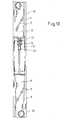
- FIG. 10 shows a section of a perforation system, which consists of a series, or coupling of individual segments 19, 20.
- Such perforation systems are u. a. used for penetration of boreholes.
- each of these segments 19, 20 consists of a carrier tube 9 and a charge carrier tube 8 arranged in the carrier tube 9.
- Perforators 14 are attached to this charge carrier tube 8.
- the individual segments 19, 20 are rigidly connected to each other via a connecting part 11.
- the connecting part 11 has for this purpose at its two ends in each case a thread on its outer circumference, with which the connecting part 11 is screwed into the segments 19, 20 or in the support tube 9.
- a detonating cord 5 is guided through the individual segments 19, 20, which grazes the perforators 14 on its rear side and causes it to ignite when ignited.
- the invention described herein improves the transfer of ignition from one segment 19 to the other segment 20.
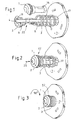
- FIGS. 1 to 4 show an enlarged section of the Figures 9 and 10 in another illustration.
- the ignition is transferred via a booster kit DW (transfer system), which in the embodiment described here consists, inter alia, of two half shells 1, 2 made of molded plastic, which form the associated receiving device 22.
- DW transfer system
- a booster 4 is choked and inserted into one of the two half-shells 1, 2, wherein the end face of the booster 4 almost flush with the end face of the receiving device 22 (see FIG. 9 ) or the two half-shells 1, 2 concludes.
- the front side of the receiving devices 21, 22 is mushroom-shaped 28, so that during assembly contaminants are displaced, or do not deposit on the end faces.
- the two half-shells 1, 2 can be plugged together, they have clamping pins 6 and recesses 13, whose positions between the two half-shells 1, 2 are arranged reversed, the clamping pins 6 fit a half-shell in the recesses 13 of the other half-shell and vice versa ,
- a spring 3 is pushed in the form of a spiral spring on the detonating cord 5.
- the two half-shells 23, 24 can also be screwed together.
- the two half-shells 23, 24 can be dismantled, a preferably wedge-shaped opening 29 is attached to the connecting edge. With commonly used tools, such as a screwdriver, then the two half-shells 23, 24 can be easily separated.
- openings 17 are introduced, through which the end face opposite the end of the receiving device 22 against the force of the spring 3 can push so positioned that it locks by a subsequent 90 degree rotation and forms a bayonet closure ,
- FIG. 2 shows the indentation process. With the arrow 25, the Eindschreibraum is designated.
- FIG. 3 the receiving device 22 is pushed in maximum.
- the spring 3 is compressed. Now the receiving device 22 is rotated by 90 degrees and released again.
- the pickup device 22 is biased in the end plate 7 (see FIG FIG. 4 ).
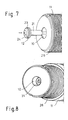
- the detonating cord 5 is guided by the segment 20 from one perforator 14 to the other and also protrudes through the connecting part 11. Good to see is the thread 26, with which the connecting part 11 in the segment 20th is screwed in.
- a booster 4 is angegeschgt or attached to the detonating cord 5 and inserted into one of the two half-shells 23, 24 and fixed by compressing the half-shells. Again, the end face 15 of the booster 4 is flush with the end face of the two half-shells 23, 24 and the receiving device 21 (see also Figures 9 and 10 ) arranged.
- an O-ring 12 (see FIG. 6 ) is inserted on the outer circumference of the receiving device 21 in a circumferential groove 27 provided for this purpose.
- the receiving device 21 is inserted into a recess 10, such that the receiving device 21 rests on a stop 18 (or paragraph). Even when pressure is applied to the receiving device 21, these can not be pressed further than to this stop 18 (see FIGS. 7 and 8 and Figures 9 and 10 ).
- the receiving device 21 exerts a pressure on the receiving device 22 and pushes it against the force of the spring 3 in the direction of the end plate 7.
- both receiving devices 21, 22 pressed together with pressure and thus also the faces of the booster 4.
- the described booster kit DW according to the invention thus consists of four temperature-resistant (preferably up to 260 ° C) and e.g. molded half shells 1, 2 made of plastic and a standard metal spring 3.
- the additional part of the booster kit DW is the profile 17 in the lower part of the end plate 7 of the charge carrier tube 8, which allows for easy installation of the two clamped half shells 1, 2 by means of a positioned pushing in and a subsequent 90 ° rotation.
- the spring 3 provides inter alia for a fixation of the two half-shells 1, 2 on the end plate 7.
- a bore or indentation 10 in the connecting part 11 At the upper end of the outer support tube 9 is a bore or indentation 10 in the connecting part 11, a same type of half-shells 23, 24 with booster installed. 4 and detonating cord 5 fixed by means of an O-ring 12.
- the spring 3 In addition to the fixation of the booster kit in the end plate 7, the spring 3 also provides flexibility. With the different diameters and the different distances between the individual booster kits, which are located in the respective carrier tubes 9 of the connecting parts 11, a dynamic tension is built up, which prevents foreign bodies from accumulating between the booster devices.
- the assembled parts can easily be taken apart with a simple tool, if necessary.
- the explosive components can thus be recovered undamaged in case of too high aging (after 5 years) or after cancellation of the use of the carrier tubes.
- the invention is thus characterized by the fact that the respective ends of the detonating cord 5, on which the booster 4 are located, are inserted immovably into two half-shells 1, 2, 23, 24 of preferably plastic. These two half shells 1, 2, 23, 24 with the end of the detonating cord 5 and the booster 4 are then inserted into the connecting part 11 and into the end plate 7 of the adjacent support tube 9. Very important here is that one of these two parts, consisting of two half-shells, in the direction of the other adjacent Part force is applied, so that between the two faces of the two booster 4 no gap is present. This force is preferably applied by the spring.
Landscapes
- Engineering & Computer Science (AREA)
- Geology (AREA)
- Mining & Mineral Resources (AREA)
- Life Sciences & Earth Sciences (AREA)
- General Life Sciences & Earth Sciences (AREA)
- Fluid Mechanics (AREA)
- Environmental & Geological Engineering (AREA)
- Physics & Mathematics (AREA)
- General Engineering & Computer Science (AREA)
- Geochemistry & Mineralogy (AREA)
- Installation Of Indoor Wiring (AREA)
- Manufacturing Of Electrical Connectors (AREA)
- Aiming, Guidance, Guns With A Light Source, Armor, Camouflage, And Targets (AREA)
- Details Of Connecting Devices For Male And Female Coupling (AREA)
- Connector Housings Or Holding Contact Members (AREA)
- Air Bags (AREA)
Abstract
Description
- Die Erfindung betrifft ein Verfahren zur Übertragung der Detonationswirkung von einer Sprengschnur zur anderen nach dem Oberbegriff des Anspruchs 1 und eine Vorrichtung nach dem Oberbegriff des Anspruchs 3.
- Perforationssysteme als ein Beispiel, bei dem eine sichere Übertragung der Detonationswirkung extrem wichtig ist, werden z. B. bei Tiefbohrlochsprengungen in der Erdöl- und Erdgasindustrie zur Anbindung der Bohrung an den Speicherhorizont eingesetzt.
- Ein Perforationssystem besteht je nach Erfordernis aus einer Mehrzahl einzelner Segmente mit Perforatoren, wobei jedes Segment aus einem Trägerrohr mit innen liegender Haltevorrichtung zur Aufnahme der Perforatoren besteht. Die einzelnen Segmente werden oft erst am Einsatzort über Verbindungsteile miteinander in Axialrichtung verbunden.
- Gezündet werden die Perforatoren durch Sprengschnüre. Da die einzelnen Segmente erst am Einsatzort verbunden werden, ist es bekannt, die Sprengschnüre so zu verbinden, dass die Zündung von einem zum anderen Segment übertragen wird. Hierzu werden die Sprengschnüre an ihren Enden mit Boostern (Zündstufen, Verstärker) versehen, wobei der erste Booster der Sprengschnur des ersten Segments mit dem angrenzenden zweiten Booster der Sprengschnur des zweiten Elements so angekoppelt wird, dass die beiden Booster in ihrer Axialrichtung gegenüber liegen, d. h. auf einer Geraden sich gegenüber liegend angeordnet sind. Durch diese Anordnung wird der Zündvorgang von einer Sprengschnur über den Booster auf den benachbarten Booster und dann auf die benachbarte Sprengschnur übertragen.
- Mit Boostern wird hier allgemein ein Donor- oder Akzeptorbooster verstanden. Gekoppelt wird der Donorbooster der einen Sprengschnur mit dem Akzeptorbooster der anderen Sprengschnur oder umgekehrt. Unter Booster ist jedoch auch ein bidirektionaler Booster verstanden. Vereinfachend wird in dieser Beschreibung daher nur allgemein von Boostern gesprochen, ohne auf die Unterscheidung zwischen Donorbooster und Akzeptorbooster oder bidirektionaler Booster einzugehen.
- Bei der Vorbereitung des Einsatzes wird das oben genannte Verbindungsteil mit seinem einen Gewinde in ein Segment eingeschraubt. Anschließend wird die Sprengschnur, mit einem Booster versehen, so in das Verbindungsteil und das Segment eingeführt, dass sich der Booster im Bereich des zum benachbarten Segments zeigenden Ende des Verbindungsteils befindet.
- Es ist bekannt, die Booster jeweils in einer Aufnahmevorrichtung zu fixieren und die Aufnahmevorrichtung fest im Segment zu verankern.
- Nachteilig ist hierbei, dass durch Temperatureinflüsse der Abstand zwischen den Stirnseiten zweier benachbarter Booster variieren kann, wodurch eine sichere Übertragung der Zündung oft nicht gewährleistet ist. Die Länge der Sprengschnur muss genau an die ausgemessene Länge angepasst werden. Außerdem können sich Fremdkörper zwischen den Stirnseiten der Booster ansammeln, die den Transfer der Zündung stören und auch dafür sorgen können, dass der benachbarte Booster nicht initiiert wird.
- Ferner benötigen diese Transfer-Kits viele Einzelteile und sind daher teuer und arbeitsintensiv. Durch variierende Außendurchmesser des Ladungsträgerrohrs werden verschiedene Transfer-Kits benötigt.
-
US 927 968 A beschreibt ein Verfahren zur Übertragung der Detonationswirkung von einer Sprengschnur zur anderen gemäβ dem Oberbegriff des Anspruchs 1 sowie eine Vorrichtung gemäβ dem Obergriff des Anspruchs 3, wobei die Sprengschnüre an ihren jeweiligen Enden einen Booster aufweisen und der Booster der einen Sprengschnur mit dem Booster der anderen Sprengschnur, auf den die Detonationswirkung übertragen werden soll, mit ihren Stirnseiten benachbarte, in Axialrichtung gegenüberliegend angeordnet werden, so dass sich die Stirnseiten der benachbarten Booster berühren. -
US 2002/139274 A1 beschreibt eine Projektilbildung eines Booster undUS-A-5,417,162 beschreibt eine Fixierung von axial gegenüberliegenden Boostern mittels Verbindungselementen, welche die Booster in ihrer gegenseitigen Lage festhalten sollen. - Der Erfindung liegt die Aufgabe zugrunde, ein Verfahren zur Übertragung der Detonationswirkung von einer Sprengschnur zur anderen nach dem Oberbegriff des Anspruchs 1 sowie eine Vorrichtung nach dem Oberbegriff des Anspruchs 3 so zu verbessern, dass die Übertragung auch bei schwierigen Verhältnissen gewährleistet ist und wenige Einzelteile benötigt werden.
- Erfindungsgemäß wird diese Aufgabe durch die Merkmale des Anspruchs 1 gelöst. Dadurch, dass zumindest ein Booster zweier benachbarter Sprengschnüre zum anderen Booster kraftbeaufschlagt wird, so dass sich die Stirnseiten der benachbarten Booster immer berühren, ist die Übertragung mit einfachen Mitteln auch bei schwierigen Einbauverhältnissen gewährleistet.
- In erfindungsgemäßer Ausgestaltung werden die Booster in Aufnahmevorrichtungen angeordnet und zumindest eine der Aufnahmevorrichtungen zweier benachbarter Sprengschnüre wird zur benachbarten Aufnahmevorrichtung kraftbeaufschlagt.
- Es sind Vorrichtungen mit einer Aneinanderkopplung einzelner Segmente bekannt, wobei jedes Segment Ladungen aus Explosivstoff enthält, und mit durch jedes Segment geführten Sprengschnüre zur Anzündung der Ladungen, die Sprengschnüre an ihren jeweiligen Enden Booster aufweisen, und der erste Booster der Sprengschnur des ersten Segments mit dem angrenzenden zweiten Booster der Sprengschnur des zweiten Segments so angekoppelt ist, dass die Booster in ihrer Axialrichtung gegenüberliegen und so beim Einsatz den Anzündvorgang vom ersten zum zweiten Segment übertragen, wobei die Booster jeweils in einer Aufnahmevorrichtung fixiert sind.
- Erfindungsgemäß ist bei diesen Vorrichtungen zumindest eine der Aufnahmevorrichtungen in Richtung zur benachbarten Aufnahmevorrichtung kraftbeaufschlagt, so dass sich die Stirnseiten der benachbarten Booster beim Einsatz der Vorrichtung immer berühren.
- Dadurch, dass zumindest eine der Aufnahmevorrichtungen in Richtung zur benachbarten Aufnahmevorrichtung kraftbeaufschlagt ist, so dass sich die Stirnseiten der benachbarten Booster beim Einsatz der Vorrichtung immer berühren, ist eine sichere Übertragung der Zündung von einem zum anderen Segment gewährleistet und es werden nur wenige Einzelteile benötigt.
- Bevorzugt ist die nicht kraftbeaufschlagte Aufnahmevorrichtung im Segment fixiert.
- Eine zweckmäßige Weiterbildung der Erfindung zeichnet sich dadurch aus, dass die Segmente beim Einsatz über ein Verbindungsteil miteinander verbunden sind und eine der benachbarten Aufnahmevorrichtungen im Verbindungsteil fixiert ist.
- Vorteilhaft ist die Vorrichtung eine Perforationskanone für Tiefbohrlochsprengungen ist und sind die Ladungen Perforatoren.
- In einer bevorzugten Ausführungsform erfolgt die Kraftbeaufschlagung der anderen Aufnahmevorrichtung über eine Feder. Es sind jedoch auch andere Arten der Kraftbeaufschlagung möglich.
- In einer Ausgestaltung der Erfindung sind die Aufnahmevorrichtungen aus temperaturbeständigen (bis 260°Celsius) Halbschalen zusammengesetzt, in die die Booster und ein Teil der angrenzenden Sprengschnur fixiert eingesetzt sind.
- Zur Kosteneinsparung sind die Halbschalen aus Kunststoff, bevorzugt gespritzt hergestellt. Der Kunststoff ist bevorzugt einer der nachfolgend genannten:
- Hochtemperaturfestes Polyamid (PAGT)
- Perfluoralcylvinylether (PFA)
- Polyetheretherketon (PEEK)
- Hexafluorpropylen (FEP)
- Ein weiteres Merkmal der Erfindung ist dadurch gekennzeichnet, dass die kraftbeaufschlagte andere Aufnahmevorrichtung über einen Bajonett-Verschluss entgegen der Kraft der Feder axial vorgespannt in einer Endplatte des zugehörenden Segments eingesetzt ist. Die Vorspannung erfolgt also hier durch eine Feder, die die andere Aufnahmevorrichtung in Richtung zur benachbarten Aufnahmevorrichtung des benachbarten Segments kraftbeaufschlagt. Es kann die Vorspannung jedoch auch durch eine andere Vorrichtung aufgebracht werden. Beim Verbinden des Segments mit dem Verbindungsteil wird die andere Aufnahmevorrichtung automatisch entgegen der Feder kraftbeaufschlagt. Es können auch beide Aufnahmevorrichtungen gegeneinander kraftbeaufschlagt sein.
- Vorteilhafterweise weisen die Halbschalen der Aufnahmevorrichtungen Klemmstifte und Ausnehmungen auf, wobei diese zwischen den beiden Halbschalen einer Aufnahmevorrichtung vertauscht oder gespiegelt angeordnet sind. Dadurch sind nur zueinander passende Halbschalen zusammensetzbar.
- In bevorzugter Ausgestaltung ist im Verbindungsteil eine Einbuchtung, vorteilhaft eine Ausbohrung angeordnet, in die eine Aufnahmevorrichtung bis zu einem Anschlag eingeschoben ist und die benachbarte andere Aufnahmevorrichtung des angrenzenden Segments in diese Einbuchtung ragt, wobei sich die Stirnseiten der zu den beiden Aufnahmevorrichtungen gehörenden Booster in der Einbuchtung befinden. Hierdurch ist der Stirnbereich der Booster vor Verunreinigung geschützt.
- Bevorzugt sind die Stirnseiten der Aufnahmevorrichtungen im Schnitt pilzförmig ausgebildet, so dass beim Zusammenbau Verschmutzungen verdrängt werden bzw. sich nicht auf den Stirnflächen ablagern.
- Zur Abdichtung und auch zum Halt weist die bis zu einem Anschlag in die Einbuchtung eingeschobene andere Aufnahmevorrichtung auf ihrer Umfangsfläche einen O-Ring auf, der an der Wandung der Einbuchtung anliegt.
- In besonderer Ausgestaltung sind an den Aufnahmevorrichtungen elektrische Kontakte angeordnet, die sich nach Kraftbeaufschlagung der Aufnahmevorrichtung berühren und so zusätzlich zur Übertragung der Detonationswirkung auch eine elektrische Verbindung der Kontakte erfolgt.
- Über die Kontakte wird bevorzugt ein Steuersignal für elektrische oder elektronische Komponenten übertragen und ist das Steuersignal ein Zündsignal an einen Sprengzünder.
- Weitere Merkmale der Erfindung zeigen die Figuren, die nachfolgend beschrieben sind.
-
Figur 10 zeigt einen Ausschnitt aus einem Perforationssystem, welches aus einer Hintereinanderreihung, bzw. Aneinanderkopplung einzelner Segmente 19, 20 besteht. - Derartige Perforationssysteme werden u. a. zur Penetrierung von Bohrlöchern verwendet.
- Jedes dieser Segmente 19, 20 besteht in der hier gezeigten Ausführungsform aus einem Trägerrohr 9 und einem im Trägerrohr 9 angeordneten Ladungsträgerrohr 8. An diesem Ladungsträgerrohr 8 sind Perforatoren 14 angebracht. In diesem Fall sind es Hohlladungs-Perforatoren, die bei Zündung das Trägerrohr 9 durchschlagen und die hier nicht gezeigte Bohrlochwandung aufbrechen bzw. penetrieren.
- Die einzelnen Segmente 19, 20 sind über ein Verbindungsteil 11 miteinander starr verbunden. Das Verbindungsteil 11 weist hierzu an seinen beiden Enden jeweils ein Gewinde auf seinem Außenumfang auf, mit denen das Verbindungsteil 11 in die Segmente 19, 20 bzw. in dessen Trägerrohr 9 eingeschraubt wird.
- Zur Zündung der Perforatoren 14 ist eine Sprengschnur 5 durch die einzelnen Segmente 19, 20 geführt, welche die Perforatoren 14 an ihrer Rückseite streift und bei Zündung zur Zündung veranlasst.
- Die hier beschriebene Erfindung verbessert den Transfer der Zündung von einem Segment 19 auf das andere Segment 20.
- Dies wird nachfolgend genauer an Hand der
Figuren 1 bis 8 und als Überblick an Hand derFigur 9 beschrieben. Dieselben Bezugszeichen in den Figuren bezeichnen auch denselben Gegenstand. - Die
Figuren 1 bis 4 zeigen einen vergrößerten Ausschnitt aus denFiguren 9 und10 in einer anderen Darstellung. - Der Transfer der Zündung erfolgt über ein Booster-Kit DW (Transfersystem), welches in der hier beschriebenen Ausführungsform u.a. aus zwei Halbschalen 1, 2 aus gespritztem Kunststoff besteht, welche die zugehörige Aufnahmevorrichtung 22 bilden.
- An die Sprengschnur 5 wird ein Booster 4 angewürgt und in eine der zwei Halbschalen 1, 2 eingelegt, wobei die Stirnfläche des Boosters 4 nahezu bündig mit der Stirnfläche der Aufnahmevorrichtung 22 (siehe
Figur 9 ) bzw. der zwei Halbschalen 1, 2 abschließt. - Die Stirnseite der Aufnahmevorrichtungen 21, 22 ist pilzförmig 28 ausgebildet, damit beim Zusammenbau Verschmutzungen verdrängt werden, bzw. sich nicht auf den Stirnflächen ablagern.
- Damit sich die beiden Halbschalen 1, 2 zusammenstecken lassen, weisen sie Klemmstifte 6 und Ausnehmungen 13 auf, deren Positionen zwischen den zwei Halbschalen 1, 2 vertauscht angeordnet sind, wobei die Klemmstifte 6 der einen Halbschale in die Ausnehmungen 13 der anderen Halbschale passen und umgekehrt. Vor dem Zusammenstecken der beiden Halbschalen 1, 2 wird eine Feder 3 in Form einer Spiralfeder auf die Sprengschnur 5 aufgeschoben. Die beiden Halbschalen 23, 24 können auch miteinander verschraubt werden.
- Damit die beiden Halbschalen 23, 24 demontiert werden können, ist an der Verbindungskante eine bevorzugt keilförmige Öffnung 29 angebracht. Mit allgemein üblichen Werkzeugen, wie zum Beispiel einem Schraubendreher, lassen sich dann die beiden Halbschalen 23, 24 leicht voneinander trennen.
- In einer Endplatte 7 des Segments 19 sind Durchbrüche 17 eingebracht, durch die sich das der Stirnfläche entgegengesetzte Ende der Aufnahmevorrichtung 22 entgegen der Kraft der Feder 3 so positioniert hineindrücken lässt, dass es sich durch eine nachfolgende 90 Grad Drehung arretiert und einen Bajonett-Verschluss bildet.
-
Figur 2 zeigt den Eindrückvorgang. Mit dem Pfeil 25 ist die Eindrückrichtung bezeichnet. - In
Figur 3 ist die Aufnahmevorrichtung 22 maximal eingedrückt. Die Feder 3 ist zusammengedrückt. Nun wird die Aufnahmevorrichtung 22 um 90 Grad gedreht und wieder losgelassen. - Als Resultat ist die Aufnahmevorrichtung 22 unter Vorspannung in der Endplatte 7 angeordnet (siehe
Figur 4 ). - Die
Figuren 5 bis 8 zeigen das Einbringen der Aufnahmevorrichtung 21 in das Verbindungsteil 11. Die Sprengschnur 5 ist durch das Segment 20 von einem Perforator 14 zum anderen geführt und durchragt auch das Verbindungsteil 11. Gut zu erkennen ist das Gewinde 26, mit dem das Verbindungsteil 11 in das Segment 20 eingeschraubt wird. - Wieder wird an die Sprengschnur 5 ein Booster 4 angewürgt bzw. befestigt und in eine der zwei Halbschalen 23, 24 eingelegt und durch Zusammenpressen der Halbschalen fixiert. Auch hier ist die Stirnseite 15 des Boosters 4 bündig zur Stirnseite der zwei Halbschalen 23, 24 bzw. der Aufnahmevorrichtung 21 (siehe auch
Figuren 9 und10 ) angeordnet. - Nachdem die Aufnahmevorrichtung 21 zusammengesetzt ist, wird ein O-Ring 12 (siehe
Figur 6 ) auf den Außenumfang der Aufnahmevorrichtung 21 in eine dafür vorgesehene umlaufende Rille 27 eingesetzt. - Anschließend wird die Aufnahmevorrichtung 21 in eine Einbuchtung 10 eingesetzt, derart, dass die Aufnahmevorrichtung 21 auf einem Anschlag 18 (bzw. auch Absatz) aufliegt. Auch bei Druckbeaufschlagung auf die Aufnahmevorrichtung 21 lässt sich diese nicht weiter als zu diesem Anschlag 18 hineindrücken (siehe
Figuren 7 und 8 undFiguren 9 und10 ). - Beim Befestigen des Verbindungsteils 11 mit dem Segment 19 (siehe
Figur 9 ) ragt die Aufnahmevorrichtung 22 in die Einbuchtung 10 im Verbindungsteil 11, bis sich die beiden Aufnahmevorrichtungen 21, 22 und damit die Booster 4 an ihren Stirnseiten berühren. - Anschließend, beim weiteren Eindrehen des Verbindungsteils 11 in das Segment 19, übt die Aufnahmevorrichtung 21 einen Druck auf die Aufnahmevorrichtung 22 aus und drückt diese entgegen der Kraft der Feder 3 in Richtung zur Endplatte 7. Dadurch sind beide Aufnahmevorrichtungen 21, 22 mit Druck aneinander gepresst und damit auch die Stirnflächen der Booster 4.
- Das beschriebene erfindungsgemäße Booster-Kit DW besteht also aus vier temperaturbeständigen (bevorzugt bis 260°C) und z.B. gespritzten Halbschalen 1, 2 aus Kunststoff und einer Standart-Metall-Feder 3.
- Nachfolgend eine weitere Beschreibung der erfindungsgemäßen Merkmale.
- Nach dem Anwürgen werden der Booster 4 und die Sprengschnur 5 in die Halbschalen eingelegt und mit Klemmstiften 6 zwischen diesen fixiert.
- Das zusätzliche Teil des Booster-Kits DW ist das Profil 17 im unteren Teil der Endplatte 7 des Ladungsträgerrohres 8, was einen einfachen Einbau der zwei zusammengeklemmten Halbschalen 1, 2 mittels eines positionierten Hineindrückens und eine nachfolgende 90°-Drehung ermöglicht.
- Die Feder 3 sorgt unter anderem für eine Fixierung der beiden Halbschalen 1, 2 an der Endplatte 7. Am oberen Ende des äußeren Trägerrohres 9 wird mit einer Ausbohrung bzw. Einbuchtung 10 im Verbindungsteil 11 eine gleiche Art von Halbschalen 23, 24 mit installiertem Booster 4 und Sprengschnur 5 mittels eines O-Ringes 12 fixiert.
- Neben der Fixierung des Booster-Kits in der Endplatte 7 sorgt die Feder 3 zudem für Flexibilität. Bei den verschiedenen Durchmessern und den unterschiedlichen Abständen zwischen den einzelnen Booster-Kits, welche sich in den jeweiligen Trägerrohren 9 der Verbindungsteile 11 befinden, wird eine dynamische Spannung aufgebaut, womit vermieden wird, dass sich Fremdkörper zwischen den Boostern ansammeln können.
- Die zusammengebauten Teile können mittels einfachem Werkzeug wieder problemlos auseinander genommen werden, falls dies nötig sein sollte. Die explosiven Komponenten können so im Falle einer zu hohen Alterung (nach 5 Jahren) oder nach Abbestellung des Einsatzes der Trägerrohre unbeschädigt zurückgewonnen werden.
- Die explosiven Komponenten (Sprengschnur 5, Booster 4) im Booster-Kit/Transfer/Kit werden mittels vorgeformter Profile 16 an der Aufnahmevorrichtung 22 gehalten bzw. geklemmt in der Endplatte 7.
- Durch die Federwirkung und Formgebung der Teile wird die Ansammlung von Fremdkörpern zwischen den zusammengebauten Boostern 4 vermieden.
- Durch die Federwirkung ist eine universelle Anwendung bei verschiedenen Trägerrohr- und Ladungsträgerrohr-Durchmessern möglich, da die Feder 3 verschiedene Abstände ausgleicht.
- Durch das Profil 17 in der Endplatte 7 und Formgebung der Teile wird die Aufnahmevorrichtung 22 fixiert.
- Das Booster-Kit/Tansfer-Kit kann mit einfachen Mitteln wieder auseinander genommen und mehrmalig verwendet werden kann, sollte es nicht zum Einsatz mit Explosivstoffen kommen.
- Die Erfindung zeichnet sich somit dadurch aus, dass die jeweiligen Enden der Sprengschnur 5, an denen sich die Booster 4 befinden, in zwei Halbschalen 1, 2, 23, 24 aus bevorzugt Kunststoff unverrückbar eingesetzt werden. Diese zwei Halbschalen 1, 2, 23, 24 mit dem Ende der Sprengschnur 5 bzw. des Boosters 4 werden dann in das Verbindungsteil 11 und in die Endplatte 7 des angrenzenden Trägerrohrs 9 eingesetzt. Ganz wesentlich ist hierbei, dass eines dieser zwei Teile, bestehend aus zwei Halbschalen, in Richtung des anderen angrenzenden Teils kraftbeaufschlagt wird, so dass zwischen den beiden Stirnflächen der beiden Booster 4 kein Spalt vorhanden ist. Diese Kraftbeaufschlagung erfolgt bevorzugt durch die Feder.
Claims (16)
- Verfahren zur Übertragung der Detonationswirkung von einer Sprengschnur (5) zur anderen, wobei die Sprengschnüre (5) an ihren jeweiligen Enden einen Booster (4) aufweisen und der Booster der einen Sprengschnur mit dem Booster der anderen Sprengschnur, auf den die Detonationswirkung übertragen werden soll, mit ihren Stirnseiten benachbart, in Axialrichtung gegenüberliegend angeordnet werden, so dass sich die Stirnseiten (15) der benachbarten Booster berühren,
dadurch gekennzeichnet, dass zumindest ein Booster zweier benachbarter Sprengschnüre zum anderen Booster kraftbeaufschlagt wird, so dass sich die Stirnseiten (15) der benachbarten Booster immer berühren. - Verfahren nach Anspruch 1,
dadurch gekennzeichnet, dass die Booster in Aufnahmevorrichtungen (21,22) angeordnet werden und zumindest eine der Aufnahmevorrichtungen (21, 22) zweier benachbarter Sprengschnüre zur benachbarten Aufnahmevorrichtung kraftbeaufschlagt wird. - Vorrichtung mit einer Aneinanderkopplung einzelner Segmente (19, 20), wobei jedes Segment (19, 20) Ladungen aus Explosivstoff enthält, und mit durch jedes Segment (19, 20) geführten Sprengschnüre (5) zur Anzündung der Ladungen, die Sprengschnüre (5) an ihren jeweiligen Enden Booster (4) aufweisen, und der erste Booster (4a) der Sprengschnur (5) des ersten Segments (19) mit dem angrenzenden zweiten Booster (4b) der Sprengschnur (5) des zweiten Segments (20) so angekoppelt ist, dass die Booster (4a, 4b) in ihrer Axialrichtung gegenüberliegen und so beim Einsatz den Anzündvorgang vom ersten (19) zum zweiten Segment (20) übertragen, wobei die Booster (4a, 4b) jeweils in einer Aufnahmevorrichtung (21, 22) fixiert sind,
dadurch gekennzeichnet, dass zumindest eine der Aufnahmevorrichtungen (21, 22) in Richtung zur benachbarten Aufnahmevorrichtung (21, 22) kraftbeaufschlagt ist, so dass sich die Stirnseiten (15) der benachbarten Booster beim Einsatz der Vorrichtung immer berühren. - Vorrichtung nach Anspruch 3,
dadurch gekennzeichnet, dass die nicht kraftbeaufschlagte Aufnahmevorrichtung im Segment fixiert ist. - Vorrichtung nach Anspruch 3 oder 4,
dadurch gekennzeichnet, dass die Segmente (19, 20) beim Einsatz über ein Verbindungsteil (11) miteinander verbunden sind und eine der benachbarten Aufnahmevorrichtungen (21, 22) im Verbindungsteil (11) fixiert ist. - Vorrichtung nach einem der Ansprüche 3 bis 5,
dadurch gekennzeichnet, dass die Vorrichtung eine Perforationskanone für Tiefbohrlochsprengungen ist und die Ladungen Perforatoren (14) sind. - Vorrichtung nach einem der Ansprüche 3 bis 6,
dadurch gekennzeichnet, dass die Kraftbeaufschlagung der anderen Aufnahmevorrichtung (22) über eine Feder (3) erfolgt. - Vorrichtung nach einem der Ansprüche 3 bis 7,
dadurch gekennzeichnet, dass die Aufnahmevorrichtungen (21, 22) aus temperaturbeständigen (bis 260° Celsius) Halbschalen (1, 2) zusammengesetzt sind, in die die Booster (4) und ein Teil der angrenzenden Sprengschnur (5) fixiert eingesetzt sind. - Vorrichtung nach Anspruch 8,
dadurch gekennzeichnet, dass die Halbschalen (1, 2) aus Kunststoff, bevorzugt gespritzt, hergestellt sind. - Vorrichtung nach einem der Ansprüche 3 bis 9,
dadurch gekennzeichnet, dass die kraftbeaufschlagte andere Aufnahmevorrichtung (22) über einen Bajonett-Verschluss entgegen der Kraft der Feder (3) axial vorgespannt in einer Endplatte (7) des zugehörenden Segments (19) eingesetzt ist. - Vorrichtung nach einem der Ansprüche 3 bis 10,
dadurch gekennzeichnet, dass die Halbschalen (1, 2, 23, 24) der Aufnahmevorrichtungen (21, 22) Klemmstifte (6) und Ausnehmungen (13) aufweisen und diese zwischen den beiden Halbschalen (1, 2, 23, 24) vertauscht angeordnet sind, wodurch nur zueinander passende Halbschalen zu einer Aufnahmevorrichtung (21, 22) zusammensetzbar sind. - Vorrichtung nach einem der Ansprüche 3 bis 11,
dadurch gekennzeichnet, dass im Verbindungsteil (11) eine Einbuchtung (10) angeordnet ist, in die eine Aufnahmevorrichtung (21) bis zu einem Anschlag (18) eingeschoben ist und die benachbarte Aufnahmevorrichtung (22) des angrenzenden Segments (19) in diese Einbuchtung (10) ragt, wobei sich die Stirnseiten (15) der beiden Booster (4a, 4b) in der Einbuchtung (10) befinden. - Vorrichtung nach einem der Ansprüche 3 bis 12,
dadurch gekennzeichnet, dass die Stirnseiten (15) der Aufnahmevorrichtungen (21, 22) im Schnitt pilzförmig (28) ausgebildet sind. - Vorrichtung nach Anspruch 12,
dadurch gekennzeichnet, dass die bis zu einem Anschlag (18) in die Einbuchtung (10) eingeschobene Aufnahmevorrichtung (21) auf ihrer Umfangsfläche einen O-Ring (12) aufweist, der an der Wandung der Einbuchtung (10) anliegt. - Vorrichtung nach einem der Ansprüche 3 bis 13,
dadurch gekennzeichnet, dass an den Aufnahmevorrichtungen (21, 22) elektrische Kontakte angeordnet sind, die sich nach Kraftbeaufschlagung der Aufnahmevorrichtung berühren und so zusätzlich zur Übertragung der Detonationswirkung auch eine elektrische Verbindung der Kontakte erfolgt. - Vorrichtung nach Anspruch 14,
dadurch gekennzeichnet, dass über die Kontakte ein Steuersignal für elektrische oder elektronische Komponenten übertragen wird und bevorzugt das Steuersignal ein Zündsignal an einen Sprengzünder ist.
Applications Claiming Priority (2)
| Application Number | Priority Date | Filing Date | Title |
|---|---|---|---|
| DE102004060137 | 2004-12-13 | ||
| PCT/EP2005/013040 WO2006063713A1 (de) | 2004-12-13 | 2005-12-06 | Sichere übertragung der zündung bei perforationssystemen |
Publications (2)
| Publication Number | Publication Date |
|---|---|
| EP1828709A1 EP1828709A1 (de) | 2007-09-05 |
| EP1828709B1 true EP1828709B1 (de) | 2010-11-24 |
Family
ID=35788316
Family Applications (1)
| Application Number | Title | Priority Date | Filing Date |
|---|---|---|---|
| EP05817431A Expired - Lifetime EP1828709B1 (de) | 2004-12-13 | 2005-12-06 | Sichere übertragung der zündung bei perforationssystemen |
Country Status (8)
| Country | Link |
|---|---|
| US (1) | US8267012B2 (de) |
| EP (1) | EP1828709B1 (de) |
| AR (1) | AR051711A1 (de) |
| AT (1) | ATE489604T1 (de) |
| CA (1) | CA2590045C (de) |
| DE (1) | DE502005010595D1 (de) |
| NO (1) | NO20072996L (de) |
| WO (1) | WO2006063713A1 (de) |
Families Citing this family (43)
| Publication number | Priority date | Publication date | Assignee | Title |
|---|---|---|---|---|
| DE102008026079A1 (de) | 2007-05-31 | 2008-12-04 | Dynaenergetics Gmbh & Co. Kg | Verfahren zur Komplettierung eines Bohrlochs |
| MX348480B (es) * | 2011-02-03 | 2017-06-14 | Baker Hughes Inc | Cartucho de conexion para sarta del fondo de la perforacion. |
| WO2014179669A1 (en) | 2013-05-03 | 2014-11-06 | Schlumberger Canada Limited | Cohesively enhanced modular perforating gun |
| US9702680B2 (en) | 2013-07-18 | 2017-07-11 | Dynaenergetics Gmbh & Co. Kg | Perforation gun components and system |
| US9822618B2 (en) | 2014-05-05 | 2017-11-21 | Dynaenergetics Gmbh & Co. Kg | Initiator head assembly |
| US9714817B1 (en) * | 2015-03-06 | 2017-07-25 | The United States Of America As Represented By The Secretary Of The Navy | Central initiating charge |
| US11255650B2 (en) * | 2016-11-17 | 2022-02-22 | XConnect, LLC | Detonation system having sealed explosive initiation assembly |
| DE202017102257U1 (de) * | 2017-04-13 | 2017-06-20 | Fr. Sobbe Gmbh | Zündvorrichtung in Kompaktausführung |
| WO2019110534A1 (en) | 2017-12-06 | 2019-06-13 | Dynaenergetics Gmbh & Co. Kg | Exposed ballistic transfer with encapsulated receiver booster |
| US11377935B2 (en) * | 2018-03-26 | 2022-07-05 | Schlumberger Technology Corporation | Universal initiator and packaging |
| US10458213B1 (en) * | 2018-07-17 | 2019-10-29 | Dynaenergetics Gmbh & Co. Kg | Positioning device for shaped charges in a perforating gun module |
| US10386168B1 (en) * | 2018-06-11 | 2019-08-20 | Dynaenergetics Gmbh & Co. Kg | Conductive detonating cord for perforating gun |
| US11339614B2 (en) | 2020-03-31 | 2022-05-24 | DynaEnergetics Europe GmbH | Alignment sub and orienting sub adapter |
| US11808093B2 (en) | 2018-07-17 | 2023-11-07 | DynaEnergetics Europe GmbH | Oriented perforating system |
| USD921858S1 (en) * | 2019-02-11 | 2021-06-08 | DynaEnergetics Europe GmbH | Perforating gun and alignment assembly |
| US11078763B2 (en) | 2018-08-10 | 2021-08-03 | Gr Energy Services Management, Lp | Downhole perforating tool with integrated detonation assembly and method of using same |
| US11994008B2 (en) | 2018-08-10 | 2024-05-28 | Gr Energy Services Management, Lp | Loaded perforating gun with plunging charge assembly and method of using same |
| US10982513B2 (en) | 2019-02-08 | 2021-04-20 | Schlumberger Technology Corporation | Integrated loading tube |
| US11293737B2 (en) * | 2019-04-01 | 2022-04-05 | XConnect, LLC | Detonation system having sealed explosive initiation assembly |
| US11913767B2 (en) | 2019-05-09 | 2024-02-27 | XConnect, LLC | End plate for a perforating gun assembly |
| US11940261B2 (en) | 2019-05-09 | 2024-03-26 | XConnect, LLC | Bulkhead for a perforating gun assembly |
| WO2020232242A1 (en) | 2019-05-16 | 2020-11-19 | Schlumberger Technology Corporation | Modular perforation tool |
| CZ310189B6 (cs) | 2019-12-10 | 2024-11-06 | DynaEnergetics Europe GmbH | Hlava rozněcovadla, rozněcovadlo a sestava rozněcovadla |
| US12084962B2 (en) | 2020-03-16 | 2024-09-10 | DynaEnergetics Europe GmbH | Tandem seal adapter with integrated tracer material |
| USD1041608S1 (en) | 2020-03-20 | 2024-09-10 | DynaEnergetics Europe GmbH | Outer connector |
| US11988049B2 (en) | 2020-03-31 | 2024-05-21 | DynaEnergetics Europe GmbH | Alignment sub and perforating gun assembly with alignment sub |
| USD904475S1 (en) | 2020-04-29 | 2020-12-08 | DynaEnergetics Europe GmbH | Tandem sub |
| USD908754S1 (en) | 2020-04-30 | 2021-01-26 | DynaEnergetics Europe GmbH | Tandem sub |
| USD1016958S1 (en) | 2020-09-11 | 2024-03-05 | Schlumberger Technology Corporation | Shaped charge frame |
| CN116568905A (zh) | 2020-11-13 | 2023-08-08 | 斯伦贝谢技术有限公司 | 大型聚能射孔弹射孔工具 |
| US12098623B2 (en) | 2020-11-13 | 2024-09-24 | Schlumberger Technology Corporation | Oriented-perforation tool |
| WO2022135749A1 (en) | 2020-12-21 | 2022-06-30 | DynaEnergetics Europe GmbH | Encapsulated shaped charge |
| US12312922B2 (en) | 2021-01-08 | 2025-05-27 | DynaEnergetics Europe GmbH | Perforating gun assembly and components |
| US12454867B2 (en) | 2021-01-09 | 2025-10-28 | Gr Energy Services Management, Lp | Integrated wellsite processing system and wellsite monitoring system and method of using same |
| US11713625B2 (en) | 2021-03-03 | 2023-08-01 | DynaEnergetics Europe GmbH | Bulkhead |
| US12366142B2 (en) | 2021-03-03 | 2025-07-22 | DynaEnergetics Europe GmbH | Modular perforating gun system |
| WO2022184732A1 (en) | 2021-03-03 | 2022-09-09 | DynaEnergetics Europe GmbH | Bulkhead and tandem seal adapter |
| US12584363B2 (en) | 2021-04-22 | 2026-03-24 | GR Energy Services, Management, LP | Orientable weight bar for a downhole tool and method of using same |
| WO2022256454A1 (en) | 2021-06-01 | 2022-12-08 | Gr Energy Services Management, L.P. | Downhole release tool with integrated igniter and method of using same |
| US12497848B2 (en) | 2021-06-01 | 2025-12-16 | Gr Energy Services Management, Lp | Igniter for activating a downhole component and method of using same |
| WO2022256452A1 (en) | 2021-06-01 | 2022-12-08 | Gr Energy Services Management, L.P. | Downhole setting tool with integrated igniter and method of using same |
| US12312925B2 (en) | 2021-12-22 | 2025-05-27 | DynaEnergetics Europe GmbH | Manually oriented internal shaped charge alignment system and method of use |
| US12580667B2 (en) | 2022-01-09 | 2026-03-17 | Gr Energy Services Management, Lp | Wellsite monitoring system with wellsite tracker and method of using same |
Family Cites Families (13)
| Publication number | Priority date | Publication date | Assignee | Title |
|---|---|---|---|---|
| US927968A (en) * | 1908-02-04 | 1909-07-13 | Jean Harle | Fuse with double action. |
| US3129663A (en) * | 1961-08-11 | 1964-04-21 | Aircraft Armaments Inc | Fittings for low energy detonating cord |
| AU439596B2 (en) * | 1970-06-29 | 1972-01-06 | Ici Australia Limited | Detonating relays for connecting lengths of detonating fuse |
| US3700269A (en) * | 1970-11-17 | 1972-10-24 | Us Navy | Sexless hose coupling |
| US3707917A (en) * | 1970-12-23 | 1973-01-02 | Whittaker Corp | Precision initiation coupler |
| US4616566A (en) * | 1984-10-05 | 1986-10-14 | Halliburton Company | Secondary high explosive booster, and method of making and method of using same |
| US4836109A (en) * | 1988-09-20 | 1989-06-06 | Halliburton Company | Control line differential firing head |
| US5155293A (en) * | 1990-12-13 | 1992-10-13 | Dresser Industries, Inc. | Safety booster for explosive systems |
| US5417162A (en) * | 1993-07-01 | 1995-05-23 | The Ensign-Bickford Company | Detonation coupling device |
| US5327835A (en) * | 1993-07-01 | 1994-07-12 | The Ensign-Bickford Company | Detonation device including coupling means |
| US6622630B2 (en) * | 1999-04-16 | 2003-09-23 | Schlumberger Technology Corporation | Booster |
| US6435095B1 (en) * | 2000-08-09 | 2002-08-20 | Mccormick Selph, Inc. | Linear ignition system |
| US20040216632A1 (en) * | 2003-04-10 | 2004-11-04 | Finsterwald Mark A. | Detonating cord interrupt device and method for transporting an explosive device |
-
2005
- 2005-12-06 EP EP05817431A patent/EP1828709B1/de not_active Expired - Lifetime
- 2005-12-06 WO PCT/EP2005/013040 patent/WO2006063713A1/de not_active Ceased
- 2005-12-06 CA CA2590045A patent/CA2590045C/en not_active Expired - Fee Related
- 2005-12-06 AT AT05817431T patent/ATE489604T1/de not_active IP Right Cessation
- 2005-12-06 DE DE502005010595T patent/DE502005010595D1/de not_active Expired - Lifetime
- 2005-12-06 US US11/721,391 patent/US8267012B2/en not_active Expired - Fee Related
- 2005-12-12 AR ARP050105185A patent/AR051711A1/es active IP Right Grant
-
2007
- 2007-06-12 NO NO20072996A patent/NO20072996L/no not_active Application Discontinuation
Also Published As
| Publication number | Publication date |
|---|---|
| CA2590045C (en) | 2012-06-19 |
| CA2590045A1 (en) | 2006-06-22 |
| WO2006063713A1 (de) | 2006-06-22 |
| DE502005010595D1 (de) | 2011-01-05 |
| US8267012B2 (en) | 2012-09-18 |
| ATE489604T1 (de) | 2010-12-15 |
| EP1828709A1 (de) | 2007-09-05 |
| US20100024674A1 (en) | 2010-02-04 |
| AR051711A1 (es) | 2007-01-31 |
| NO20072996L (no) | 2007-09-05 |
Similar Documents
| Publication | Publication Date | Title |
|---|---|---|
| EP1828709B1 (de) | Sichere übertragung der zündung bei perforationssystemen | |
| EP3478971B1 (de) | Selbstsichernde bolzenhaltevorrichtung | |
| DE10261595B4 (de) | Rohrverbinder | |
| DE19650530A1 (de) | Rückhaltevorrichtung für geformte Ladung | |
| DE102014015679A1 (de) | Kippdübel und Verfahren zur Montage eines Kippdübels | |
| DE2757216B2 (de) | Verbinder für optische Fasern | |
| DE3346505A1 (de) | Faseroptisches durchkontaktierungsmodul und verfahren zu dessen herstellung | |
| WO2005033472A1 (de) | Perforationskanonensystem mit selbstverschliessenden durchschusslöchern | |
| EP3839304A1 (de) | Rückschlagventil sowie anschlusseinrichtung für ein rückschlagventil | |
| DE2831049A1 (de) | Scherbolzenverbindung, scherbolzenkombination und unter verwendung derselben hergestellte raketensicherungsvorrichtung | |
| AT396994B (de) | Vorrichtung zum verbinden von sprengschnur und zünder | |
| DE1615823A1 (de) | Steckkontakt mit Verriegelung | |
| DE102018107507A1 (de) | "Anschlussvorrichtung für Medienleitungen" | |
| EP1770320B1 (de) | Lösbare Steckverbindung für Rohrleitungen | |
| DE102005058356A1 (de) | Sichere Übertragung der Zündung bei Perforationssystemen | |
| EP3453866B1 (de) | Montagesystem zum aufbringen eines dichtringes | |
| DE102010052189B4 (de) | Vorrichtung zum Halten und Abdichten eines Rohres | |
| EP0002729B1 (de) | Muffen-Rohrformstück für Luftheizungsleitungen od.dgl. | |
| DE2302003C3 (de) | Patrone zur Sprengverbindung stabförmiger Metallglieder mit einer Metallhülse | |
| DE102007016488B3 (de) | Penetrationsfähiges Geschoss | |
| EP3153757B1 (de) | Lösbare steckverbindung für rohrleitungen | |
| DE2539947A1 (de) | Hohlladungsanordnung fuer bohrloecher | |
| EP0430866A2 (de) | Verbindungsstück | |
| EP2476939A2 (de) | Anschlussverbinder zum Anschließen eines Rohrendes | |
| DE2738454C3 (de) | Lösbare Muffensteckverbindung |
Legal Events
| Date | Code | Title | Description |
|---|---|---|---|
| PUAI | Public reference made under article 153(3) epc to a published international application that has entered the european phase |
Free format text: ORIGINAL CODE: 0009012 |
|
| 17P | Request for examination filed |
Effective date: 20070713 |
|
| AK | Designated contracting states |
Kind code of ref document: A1 Designated state(s): AT BE BG CH CY CZ DE DK EE ES FI FR GB GR HU IE IS IT LI LT LU LV MC NL PL PT RO SE SI SK TR |
|
| RIN1 | Information on inventor provided before grant (corrected) |
Inventor name: EICHTEN, OLIVER AXEL Inventor name: PEETERS, ROLAND Inventor name: VEEHMAYER, MALTE |
|
| DAX | Request for extension of the european patent (deleted) | ||
| 17Q | First examination report despatched |
Effective date: 20090820 |
|
| GRAP | Despatch of communication of intention to grant a patent |
Free format text: ORIGINAL CODE: EPIDOSNIGR1 |
|
| GRAS | Grant fee paid |
Free format text: ORIGINAL CODE: EPIDOSNIGR3 |
|
| GRAA | (expected) grant |
Free format text: ORIGINAL CODE: 0009210 |
|
| AK | Designated contracting states |
Kind code of ref document: B1 Designated state(s): AT BE BG CH CY CZ DE DK EE ES FI FR GB GR HU IE IS IT LI LT LU LV MC NL PL PT RO SE SI SK TR |
|
| REG | Reference to a national code |
Ref country code: GB Ref legal event code: FG4D Free format text: NOT ENGLISH |
|
| REG | Reference to a national code |
Ref country code: CH Ref legal event code: EP |
|
| REG | Reference to a national code |
Ref country code: IE Ref legal event code: FG4D |
|
| REF | Corresponds to: |
Ref document number: 502005010595 Country of ref document: DE Date of ref document: 20110105 Kind code of ref document: P |
|
| REG | Reference to a national code |
Ref country code: RO Ref legal event code: EPE |
|
| REG | Reference to a national code |
Ref country code: NL Ref legal event code: VDEP Effective date: 20101124 |
|
| LTIE | Lt: invalidation of european patent or patent extension |
Effective date: 20101124 |
|
| PG25 | Lapsed in a contracting state [announced via postgrant information from national office to epo] |
Ref country code: LT Free format text: LAPSE BECAUSE OF FAILURE TO SUBMIT A TRANSLATION OF THE DESCRIPTION OR TO PAY THE FEE WITHIN THE PRESCRIBED TIME-LIMIT Effective date: 20101124 |
|
| PG25 | Lapsed in a contracting state [announced via postgrant information from national office to epo] |
Ref country code: BG Free format text: LAPSE BECAUSE OF FAILURE TO SUBMIT A TRANSLATION OF THE DESCRIPTION OR TO PAY THE FEE WITHIN THE PRESCRIBED TIME-LIMIT Effective date: 20110224 Ref country code: NL Free format text: LAPSE BECAUSE OF FAILURE TO SUBMIT A TRANSLATION OF THE DESCRIPTION OR TO PAY THE FEE WITHIN THE PRESCRIBED TIME-LIMIT Effective date: 20101124 Ref country code: PT Free format text: LAPSE BECAUSE OF FAILURE TO SUBMIT A TRANSLATION OF THE DESCRIPTION OR TO PAY THE FEE WITHIN THE PRESCRIBED TIME-LIMIT Effective date: 20110324 Ref country code: FI Free format text: LAPSE BECAUSE OF FAILURE TO SUBMIT A TRANSLATION OF THE DESCRIPTION OR TO PAY THE FEE WITHIN THE PRESCRIBED TIME-LIMIT Effective date: 20101124 Ref country code: SI Free format text: LAPSE BECAUSE OF FAILURE TO SUBMIT A TRANSLATION OF THE DESCRIPTION OR TO PAY THE FEE WITHIN THE PRESCRIBED TIME-LIMIT Effective date: 20101124 Ref country code: CY Free format text: LAPSE BECAUSE OF FAILURE TO SUBMIT A TRANSLATION OF THE DESCRIPTION OR TO PAY THE FEE WITHIN THE PRESCRIBED TIME-LIMIT Effective date: 20101124 Ref country code: LV Free format text: LAPSE BECAUSE OF FAILURE TO SUBMIT A TRANSLATION OF THE DESCRIPTION OR TO PAY THE FEE WITHIN THE PRESCRIBED TIME-LIMIT Effective date: 20101124 Ref country code: IS Free format text: LAPSE BECAUSE OF FAILURE TO SUBMIT A TRANSLATION OF THE DESCRIPTION OR TO PAY THE FEE WITHIN THE PRESCRIBED TIME-LIMIT Effective date: 20110324 Ref country code: SE Free format text: LAPSE BECAUSE OF FAILURE TO SUBMIT A TRANSLATION OF THE DESCRIPTION OR TO PAY THE FEE WITHIN THE PRESCRIBED TIME-LIMIT Effective date: 20101124 |
|
| PGFP | Annual fee paid to national office [announced via postgrant information from national office to epo] |
Ref country code: RO Payment date: 20101227 Year of fee payment: 6 |
|
| REG | Reference to a national code |
Ref country code: IE Ref legal event code: FD4D |
|
| BERE | Be: lapsed |
Owner name: DYNAENERGETICS G.M.B.H. & CO. KG Effective date: 20101231 |
|
| PG25 | Lapsed in a contracting state [announced via postgrant information from national office to epo] |
Ref country code: GR Free format text: LAPSE BECAUSE OF FAILURE TO SUBMIT A TRANSLATION OF THE DESCRIPTION OR TO PAY THE FEE WITHIN THE PRESCRIBED TIME-LIMIT Effective date: 20110225 |
|
| PG25 | Lapsed in a contracting state [announced via postgrant information from national office to epo] |
Ref country code: IE Free format text: LAPSE BECAUSE OF FAILURE TO SUBMIT A TRANSLATION OF THE DESCRIPTION OR TO PAY THE FEE WITHIN THE PRESCRIBED TIME-LIMIT Effective date: 20101124 Ref country code: EE Free format text: LAPSE BECAUSE OF FAILURE TO SUBMIT A TRANSLATION OF THE DESCRIPTION OR TO PAY THE FEE WITHIN THE PRESCRIBED TIME-LIMIT Effective date: 20101124 Ref country code: ES Free format text: LAPSE BECAUSE OF FAILURE TO SUBMIT A TRANSLATION OF THE DESCRIPTION OR TO PAY THE FEE WITHIN THE PRESCRIBED TIME-LIMIT Effective date: 20110307 Ref country code: CZ Free format text: LAPSE BECAUSE OF FAILURE TO SUBMIT A TRANSLATION OF THE DESCRIPTION OR TO PAY THE FEE WITHIN THE PRESCRIBED TIME-LIMIT Effective date: 20101124 Ref country code: MC Free format text: LAPSE BECAUSE OF NON-PAYMENT OF DUE FEES Effective date: 20101231 |
|
| REG | Reference to a national code |
Ref country code: CH Ref legal event code: PL |
|
| PG25 | Lapsed in a contracting state [announced via postgrant information from national office to epo] |
Ref country code: DK Free format text: LAPSE BECAUSE OF FAILURE TO SUBMIT A TRANSLATION OF THE DESCRIPTION OR TO PAY THE FEE WITHIN THE PRESCRIBED TIME-LIMIT Effective date: 20101124 Ref country code: PL Free format text: LAPSE BECAUSE OF FAILURE TO SUBMIT A TRANSLATION OF THE DESCRIPTION OR TO PAY THE FEE WITHIN THE PRESCRIBED TIME-LIMIT Effective date: 20101124 Ref country code: SK Free format text: LAPSE BECAUSE OF FAILURE TO SUBMIT A TRANSLATION OF THE DESCRIPTION OR TO PAY THE FEE WITHIN THE PRESCRIBED TIME-LIMIT Effective date: 20101124 |
|
| PG25 | Lapsed in a contracting state [announced via postgrant information from national office to epo] |
Ref country code: BE Free format text: LAPSE BECAUSE OF NON-PAYMENT OF DUE FEES Effective date: 20101231 |
|
| PLBE | No opposition filed within time limit |
Free format text: ORIGINAL CODE: 0009261 |
|
| STAA | Information on the status of an ep patent application or granted ep patent |
Free format text: STATUS: NO OPPOSITION FILED WITHIN TIME LIMIT |
|
| PG25 | Lapsed in a contracting state [announced via postgrant information from national office to epo] |
Ref country code: LI Free format text: LAPSE BECAUSE OF NON-PAYMENT OF DUE FEES Effective date: 20101231 Ref country code: CH Free format text: LAPSE BECAUSE OF NON-PAYMENT OF DUE FEES Effective date: 20101231 |
|
| 26N | No opposition filed |
Effective date: 20110825 |
|
| REG | Reference to a national code |
Ref country code: DE Ref legal event code: R097 Ref document number: 502005010595 Country of ref document: DE Effective date: 20110825 |
|
| PG25 | Lapsed in a contracting state [announced via postgrant information from national office to epo] |
Ref country code: IT Free format text: LAPSE BECAUSE OF FAILURE TO SUBMIT A TRANSLATION OF THE DESCRIPTION OR TO PAY THE FEE WITHIN THE PRESCRIBED TIME-LIMIT Effective date: 20101124 |
|
| REG | Reference to a national code |
Ref country code: FR Ref legal event code: ST Effective date: 20111125 |
|
| PG25 | Lapsed in a contracting state [announced via postgrant information from national office to epo] |
Ref country code: FR Free format text: LAPSE BECAUSE OF NON-PAYMENT OF DUE FEES Effective date: 20110124 |
|
| PG25 | Lapsed in a contracting state [announced via postgrant information from national office to epo] |
Ref country code: AT Free format text: LAPSE BECAUSE OF NON-PAYMENT OF DUE FEES Effective date: 20101206 |
|
| REG | Reference to a national code |
Ref country code: AT Ref legal event code: MM01 Ref document number: 489604 Country of ref document: AT Kind code of ref document: T Effective date: 20101206 |
|
| PG25 | Lapsed in a contracting state [announced via postgrant information from national office to epo] |
Ref country code: HU Free format text: LAPSE BECAUSE OF FAILURE TO SUBMIT A TRANSLATION OF THE DESCRIPTION OR TO PAY THE FEE WITHIN THE PRESCRIBED TIME-LIMIT Effective date: 20110525 Ref country code: LU Free format text: LAPSE BECAUSE OF NON-PAYMENT OF DUE FEES Effective date: 20101206 |
|
| PG25 | Lapsed in a contracting state [announced via postgrant information from national office to epo] |
Ref country code: TR Free format text: LAPSE BECAUSE OF FAILURE TO SUBMIT A TRANSLATION OF THE DESCRIPTION OR TO PAY THE FEE WITHIN THE PRESCRIBED TIME-LIMIT Effective date: 20101124 |
|
| PGFP | Annual fee paid to national office [announced via postgrant information from national office to epo] |
Ref country code: DE Payment date: 20130228 Year of fee payment: 8 |
|
| REG | Reference to a national code |
Ref country code: DE Ref legal event code: R082 Ref document number: 502005010595 Country of ref document: DE Representative=s name: ZIMMERMANN & PARTNER, DE Ref country code: DE Ref legal event code: R082 Ref document number: 502005010595 Country of ref document: DE Representative=s name: ZIMMERMANN & PARTNER PATENTANWAELTE MBB, DE |
|
| REG | Reference to a national code |
Ref country code: DE Ref legal event code: R119 Ref document number: 502005010595 Country of ref document: DE |
|
| PG25 | Lapsed in a contracting state [announced via postgrant information from national office to epo] |
Ref country code: RO Free format text: LAPSE BECAUSE OF NON-PAYMENT OF DUE FEES Effective date: 20131206 |
|
| REG | Reference to a national code |
Ref country code: DE Ref legal event code: R119 Ref document number: 502005010595 Country of ref document: DE Effective date: 20140701 |
|
| PG25 | Lapsed in a contracting state [announced via postgrant information from national office to epo] |
Ref country code: DE Free format text: LAPSE BECAUSE OF NON-PAYMENT OF DUE FEES Effective date: 20140701 |
|
| PGFP | Annual fee paid to national office [announced via postgrant information from national office to epo] |
Ref country code: GB Payment date: 20141229 Year of fee payment: 10 |
|
| GBPC | Gb: european patent ceased through non-payment of renewal fee |
Effective date: 20151206 |
|
| PG25 | Lapsed in a contracting state [announced via postgrant information from national office to epo] |
Ref country code: GB Free format text: LAPSE BECAUSE OF NON-PAYMENT OF DUE FEES Effective date: 20151206 |