EP1828794B1 - Gestion de l'etat d'une batterie sans fil pour dispositifs medicaux - Google Patents
Gestion de l'etat d'une batterie sans fil pour dispositifs medicaux Download PDFInfo
- Publication number
- EP1828794B1 EP1828794B1 EP05799813.0A EP05799813A EP1828794B1 EP 1828794 B1 EP1828794 B1 EP 1828794B1 EP 05799813 A EP05799813 A EP 05799813A EP 1828794 B1 EP1828794 B1 EP 1828794B1
- Authority
- EP
- European Patent Office
- Prior art keywords
- battery
- wireless
- charge level
- ray detector
- set forth
- Prior art date
- Legal status (The legal status is an assumption and is not a legal conclusion. Google has not performed a legal analysis and makes no representation as to the accuracy of the status listed.)
- Expired - Lifetime
Links
Images



Classifications
-
- A—HUMAN NECESSITIES
- A61—MEDICAL OR VETERINARY SCIENCE; HYGIENE
- A61N—ELECTROTHERAPY; MAGNETOTHERAPY; RADIATION THERAPY; ULTRASOUND THERAPY
- A61N1/00—Electrotherapy; Circuits therefor
- A61N1/18—Applying electric currents by contact electrodes
- A61N1/32—Applying electric currents by contact electrodes alternating or intermittent currents
- A61N1/36—Applying electric currents by contact electrodes alternating or intermittent currents for stimulation
- A61N1/362—Heart stimulators
- A61N1/37—Monitoring; Protecting
- A61N1/3706—Pacemaker parameters
- A61N1/3708—Pacemaker parameters for power depletion
-
- G—PHYSICS
- G01—MEASURING; TESTING
- G01R—MEASURING ELECTRIC VARIABLES; MEASURING MAGNETIC VARIABLES
- G01R31/00—Arrangements for testing electric properties; Arrangements for locating electric faults; Arrangements for electrical testing characterised by what is being tested not provided for elsewhere
- G01R31/36—Arrangements for testing, measuring or monitoring the electrical condition of accumulators or electric batteries, e.g. capacity or state of charge [SoC]
- G01R31/3644—Constructional arrangements
- G01R31/3647—Constructional arrangements for determining the ability of a battery to perform a critical function, e.g. cranking
-
- G—PHYSICS
- G01—MEASURING; TESTING
- G01R—MEASURING ELECTRIC VARIABLES; MEASURING MAGNETIC VARIABLES
- G01R31/00—Arrangements for testing electric properties; Arrangements for locating electric faults; Arrangements for electrical testing characterised by what is being tested not provided for elsewhere
- G01R31/36—Arrangements for testing, measuring or monitoring the electrical condition of accumulators or electric batteries, e.g. capacity or state of charge [SoC]
- G01R31/3644—Constructional arrangements
- G01R31/3648—Constructional arrangements comprising digital calculation means, e.g. for performing an algorithm
Definitions
- the present invention relates to wireless patient devices. It finds particular application with physiological monitoring devices that are connected to the patient and communicate wirelessly to each other and a central unit. However, the invention is also applicable to dosing devices, such as perfusion pumps, which are wirelessly controlled, and the like.
- patient monitors such as an ekg sensor, pulse sensor, blood oxygen sensor, and the like are each connected with its control unit by a cable.
- This maze of cables is inconvenient to set up and uncomfortable for the patient.
- moving the patient typically requires disconnecting the cables are reconnecting them after the move.
- the patient is left unmonitored during the move.
- a battery operated component is equipped with a sensor that measures the battery's current charge level. Some provide a simple green light for a strong charge and a red light for a weak charge, i.e., the battery is about to run out. Others provide a gauge which indicates the remaining portion of battery life. Battery life gauges merely indicate a level of charge-not when a battery will run out. Nominally similar batteries will hold different amounts of maximum charge or discharge at different rates. As batteries age, they tend to have progressively shorter lives
- a medical system is provided as defined in claim 1.
- a method of monitoring the life of a battery of a wireless medical component is provided as defined in claim 11.
- One advantage of the present invention is better reliability for systems with battery operated components.
- Another advantage is better battery management of several similar devices.
- Another advantage is increased reliability for battery operated components.
- Another advantage lies in increased safety of battery operated critical systems.
- the invention may take form in various components and arrangements of components, and in various steps and arrangements of steps.
- the drawings are only for purposes of illustrating the preferred embodiments and are not to be construed as limiting the invention.
- a wireless medical component 10 is used in a clinical fashion. Being wireless, the component 10 has the advantage of mobility, and is not anchored to a certain room or spot. As the component 10 still uses electrical power to perform its function or communicate, it has a battery or other portable power supply. With reference to FIGURE 2 , the component 10 is shown in more detail.
- the component 10 is powered by a rechargeable power supply or battery 12.
- the battery 12 is rechargeable, such that a user can plug the component 10 in to a docking station to recharge it when not in use. It is to be understood that conventional non-rechargeable batteries are also contemplated, though they are slightly less convenient.
- the battery 12 provides power to a functional element 14, such as an ekg senor, pulse sensor, blood oxygen sensor, blood measure sensor, brain wave sensor temperature sensor, perfusion pump, IV drip controller, patient identification tag or wrist band, pacemaker, respirator, x-ray detector, MRI coil, or the like.
- a functional element 14 such as an ekg senor, pulse sensor, blood oxygen sensor, blood measure sensor, brain wave sensor temperature sensor, perfusion pump, IV drip controller, patient identification tag or wrist band, pacemaker, respirator, x-ray detector, MRI coil, or the like.
- the components associated with each patient communicate with each other and form an ad hoc network.
- the component 10 also includes a battery level or charge level monitor, e.g. a voltage monitor 16 that continuously monitors the voltage output of the battery 12.
- a voltage monitor 16 that continuously monitors the voltage output of the battery 12.
- the voltage monitor only takes voltage readings, and does not interpret the data it collects. On-board interpretation of the data is contemplated and would be more costly in that it might include extra circuit components, such as an extra dedicated microprocessor which would increase monetary cost and shorten the battery life.
- a microprocessing control unit 18 processes the monitored function data, a device ID, possibly a network or patient identifier, information received from other components, and the like along with the battery level data for wireless transfer.
- a wireless transmitter 20 transmits the data to a receiver 22 connected with a host device 24.
- the wireless transmitter is preferably a low power, short range transmitter, such as infra-red, Bluetooth, ZigBee, low strength radio frequency (RF) waves, or the like.
- RF radio frequency
- the host device 24 is connected with the receiver by a transmission cable, a wireless LAN, or the like. Alternately, the host device 24 is dedicated to a specific component and is mounted with the receiver 22. For example, the recharging station, the receiver 22 and the host device 24 can be mounted to a mobile cart. Rather than continuous transmissions, the control unit 18 can keep a rotating log of recent measurements and transmit all the measurements from recent history periodically, when polled by the host device 24, or the like.
- a portable x-ray source 26 transmits diagnostic x-rays through a subject located on a support surface 28, typically the patient's bed.
- the patient would be x-rayed in their bed and the detector 10 placed between them and the bed.
- the detector 10 can be used in conjunction with a stationary x-ray unit 26.
- the patients would be transported to a dedicated x-ray room.
- the component 10 is depicted in FIGURE 1 as an x-ray detector, but the present application is available to myriad other battery powered medical devices.
- the transmitter 20 of the component 10 regularly transmits packets of information to the host device 24 that contain the voltage readings, the image data, and the like.
- the data packets preferably contain a component identification, that may include the type of battery 12 that powers the component.
- the transmitter transmits packets of data after each image is taken and battery information periodically in between. A reasonable balance is desired between battery conservation and constant battery monitoring.
- the transmitter 20 transmits battery information every five minutes, but this length of time can be shorter or longer, depending on the application.
- the receiver 22 receives the data packet containing the voltage data from the component 10, the data packet is demodulated by a host control unit 30, converting the wireless signal back into voltage data and diagnostic data.
- the diagnostic data is sent to a diagnostic data processor 32, such as an image processor in the x-ray imaging embodiment and a battery status monitor 34.
- a diagnostic data processor 32 such as an image processor in the x-ray imaging embodiment and a battery status monitor 34.
- the receiver 22 and the host control unit 30, and the data processor 32 can collectively be referred to as a subsystem.
- the subsystem preferably performs an automatic picture or graphic processing operation with no user input or interface while the battery status monitor 34 interprets the voltage data. Generally, as a battery drains, its output voltage wanes.
- the battery status monitor 34 determines the state of charge of the battery.
- the battery status monitor 34 at least includes software that compares the current operating voltage of the battery 12 to pre-determined percentage thresholds. For instance, if the current operating voltage is greater than an upper threshold, the battery status monitor 34 may rate the remaining charge of the battery 12 as “good.” If the operating voltage is between upper and lower thresholds, the monitor 34 may report the battery status as "low.” Finally, if the battery's 12 current voltage is below the lower threshold, the monitor 34 may label it as "critical.” In addition, the battery status monitor 34 may be able to report if the state of the battery is unknown, such as if the component 10 leaves the reception range of the receiver 22 for more than a pre-determined number of expected transmissions. The preferred battery status monitor 34 is able to provide a user with more exact information, so the user can more accurately determine whether it is prudent to replace or charge the battery, or to wait and let the component 10 operate longer at its current status.
- the battery status monitor 34 can chart a voltage/remaining usage history. That is, for this battery in this device, for the procedures it commonly or is scheduled to perform, the historical data enables the number of remaining procedures on the battery to be projected or, for continuous monitoring operations, the time the battery will run out. Charging or replacement of the battery 12 is indicated by a significant increase or spike in the actual reported operating voltage. As shown in FIGURE 3 , from actual reported voltage data points, coupled with typical drainage patterns, the battery status monitor 34 can extrapolate an expected battery life curve, and determine an estimated critical point 38 in time where the battery operating voltage will become insufficient to operate the component 10 or perform further procedures completely.
- the battery history memory 36 can retain the battery life curves of the battery 12 assuming that it is rechargeable. As the battery 12 grows older and its ability to hold a charge wanes, the expected battery life will grow shorter. Once the battery status monitor 34 compares the battery's 12 ability to hold a charge with a degree of degradation it recommends replacement of the rechargeable battery, rather than just charging it.
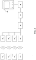
- each receiver 22 1 - 22 n is wired to a common host control unit 30 via a high speed switch 40, or other networking device.
- a single receiver 22 1 is responsible for a single component 10 1 .
- the receiver 22 1 may be programmed to attach the ID of the component 10 1 or its battery for which it is responsible as a rider to the signal.
- This embodiment may be useful, for example, if a component 10 is meant for use in one room only, such as an MRI receive coil. It may also be useful in a residential setting, such as to monitor the battery life of a respirator.
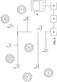
- FIGURE 5 shows multiple components 10 1 - 10 n that transmit to a common receiver 22.
- This receiver is connected to the common host control unit 30 and the battery status monitor 34 as in FIGURE 1 .
- This embodiment may be useful where multiple devices operate in a common room or travel together as a set.
- wireless receivers 22 are distributed around an area with overlapping areas of coverage creating an aggregate wireless "hot spot" where any one of many components 10 can transmit to any of the receivers.
- any one of many components 10 can transmit to any of the receivers.
- the components 10 are preferably programmed to transmit identifiers in each signal packet. Should multiple receivers detect the same transmission from the component 10 either the host control unit 30 can reconcile duplicative received transmissions.
- the battery status monitor 34 is displayed on a user interface 42.
- the component is identified along with its estimated battery life.
- the battery status monitor 34 is a program that runs in the background of a computer's operating system. The user can access the program by clicking an icon, bringing up a list of the active components 10 that the battery status monitor 34 is currently monitoring.
- the nurse or technician is shown the remaining battery life of the selected component.
- a list of the components with sufficient battery life to perform the procedure is displayed. If a component with insufficient battery life to complete the procedure is selected, a warning can be displayed.
- the host device can match battery requirements with remaining battery life and schedule which component will be assigned to each procedure.
- battery maintenance may be an assigned task.
- a nurse's aide or other technician can easily access a list of components and their battery statuses, and see which components should be returned to their chargers, or have their batteries replaced.
- the battery life information can be routed to a battery maintenance center.
- an audible or visual alarm may be sounded either at the component location, the host device location, and nurses' station or the like to warn that a component 10 battery 12 is within a preselected threshold of dying.
- the transmitter 20 could instead be a transceiver.
- the current battery status could then be transmitted back to the component which may affect the activity of the component.
- a component with some amount of random access memory (RAM) may receive a message that its battery 12 is critically low. This may trigger the component to enter a state in which it conserves power by continuing only essential functions, such as ensuring that any information stored in RAM will remain intact. If the component is in a network, the low battery signal can transfer some or all or its functions to other network components that have redundant capacity regarding one or more of its functions.
- RAM random access memory
Landscapes
- Health & Medical Sciences (AREA)
- Heart & Thoracic Surgery (AREA)
- Life Sciences & Earth Sciences (AREA)
- Veterinary Medicine (AREA)
- General Physics & Mathematics (AREA)
- Engineering & Computer Science (AREA)
- Biomedical Technology (AREA)
- Nuclear Medicine, Radiotherapy & Molecular Imaging (AREA)
- Radiology & Medical Imaging (AREA)
- Animal Behavior & Ethology (AREA)
- General Health & Medical Sciences (AREA)
- Public Health (AREA)
- Biophysics (AREA)
- Physics & Mathematics (AREA)
- Cardiology (AREA)
- Measuring And Recording Apparatus For Diagnosis (AREA)
- Secondary Cells (AREA)
- Measurement Of The Respiration, Hearing Ability, Form, And Blood Characteristics Of Living Organisms (AREA)
- Electrotherapy Devices (AREA)
- Infusion, Injection, And Reservoir Apparatuses (AREA)
- Apparatus For Radiation Diagnosis (AREA)
- Measurement And Recording Of Electrical Phenomena And Electrical Characteristics Of The Living Body (AREA)
- Measuring Pulse, Heart Rate, Blood Pressure Or Blood Flow (AREA)
- Magnetic Resonance Imaging Apparatus (AREA)
- Charge And Discharge Circuits For Batteries Or The Like (AREA)
Claims (13)
- Système médical, comprenant :un détecteur de rayons X sans fil (10), incluant :un composant fonctionnel (14) qui est configuré pour générer des données d'image selon les rayons X reçus d'une source de rayons X (26),une source d'alimentation sans fil (12) qui est configurée pour alimenter le composant fonctionnel (14),un dispositif de surveillance de niveau de charge (16) qui est configuré pour surveiller un niveau de charge de la source d'alimentation sans fil (12) et pour générer des données de niveau de charge correspondantes,un émetteur (20) qui est configuré pour transmettre sans fil des signaux portant les données d'image et les données de niveau de charge à partir du composant fonctionnel (14) et du dispositif de surveillance de niveau de charge (16) ;un dispositif hôte (24) connecté à un récepteur (22) qui est configuré pour recevoir les signaux transmis à partir du détecteur de rayons X sans fil (10),dans lequel le dispositif hôte (24) inclut :un processeur d'image (32) qui est configuré pour traiter les données d'image reçues du composant fonctionnel (14), et ;un moyen d'analyse de batterie (34) qui est configuré pour analyser les données de niveau de charge reçues et pour déterminer à partir de celles-ci un temps de fonctionnement restant estimé du détecteur de rayons X sans fil (10).
- Système médical selon la revendication 1, dans lequel la source d'alimentation sans fil inclut une batterie rechargeable (12) pour fournir de l'énergie au composant fonctionnel (14), dans lequel le dispositif de surveillance de niveau de charge (16) est configuré pour surveiller la tension de sortie de la batterie rechargeable (12).
- Système médical selon la revendication 1, dans lequel le détecteur de rayons X sans fil (10) inclut en outre :
une unité de commande de composant de microtraitement (18) pour assembler les données d'image provenant du composant fonctionnel (14) et les données de niveau de charge provenant du dispositif de surveillance de niveau de charge (16) en un signal transmissible. - Système médical selon la revendication 3, dans lequel l'émetteur inclut un émetteur par radiofréquence à faible portée (20).
- Système médical selon la revendication 1, dans lequel le moyen d'analyse de batterie (34) est configuré pour interpréter les données de niveau de charge reçues du dispositif de surveillance de niveau de charge (16) et pour les convertir en une durée de vie de batterie prévue.
- Système médical selon la revendication 5, dans lequel le dispositif hôte (24) inclut une interface utilisateur (42) sur laquelle un utilisateur peut visualiser la durée de vie prévue de la batterie et les données d'image reçues du composant fonctionnel (14).
- Système médical selon la revendication 2, dans lequel le dispositif hôte (24) inclut en outre :
une mémoire de données historiques (36) pour stocker des données historiques sur les intensités de décharge de la batterie, dans lequel le moyen d'analyse de batterie (34) est configuré pour déterminer à partir de la tension de sortie reçue et des données historiques à (1) à une charge de batterie restante et à (2) une durée de vie utile restante viable de la batterie rechargeable. - Système médical selon la revendication 1, dans lequel le dispositif hôte (24) est portable conjointement avec le détecteur de rayons X sans fil (10).
- Système médical selon la revendication 1, incluant en outre d'autres détecteurs de rayons X sans fil (101 - 10n) qui sont configurés pour communiquer avec le dispositif hôte (24).
- Système médical selon la revendication 9, dans lequel les autres détecteurs de rayons X sans fil (1011 - 101n) sont configurés pour communiquer avec d'autres dispositifs hôtes (241 - 24n).
- Procédé de surveillance de la durée de vie d'une batterie (12) d'un détecteur de rayons X sans fil (10), comprenant :la génération de données d'image selon les rayons X reçus d'une source de rayons X (26) avec un composant fonctionnel (14) du détecteur de rayons X sans fil (10) ;la surveillance d'un niveau de charge d'une source d'alimentation sans fil (12) du composant médical sans fil (10) qui alimente le composant fonctionnel (14) avec un dispositif de surveillance de niveau de charge (16) du détecteur de rayons X sans fil (10) ;l'émission sans fil de signaux transportant les données d'image et les données de niveau de charge à partir du composant fonctionnel (14) et du dispositif de surveillance de niveau de charge (16) avec un émetteur (20) du détecteur de rayons X sans fil (10) ;la réception des signaux transmis à partir du détecteur de rayons X sans fil (10) avec un récepteur (22) connecté à un dispositif hôte (24) ;dans lequel le procédé comprend en outre :le traitement des données d'image reçues du composant fonctionnel (14) avec un processeur d'image (32) du dispositif hôte (24), et ;l'analyse des données de niveau de charge reçues et la détermination, avec un moyen d'analyse de batterie (34) du dispositif hôte (24), à partir de celles-ci, d'un temps de fonctionnement restant estimé du détecteur de rayons X sans fil (10).
- Procédé selon la revendication 11, dans lequel en outre la source d'alimentation sans fil est une batterie rechargeable (12) et la détermination du temps de fonctionnement restant inclut :la lecture d'un niveau de tension courant de la batterie rechargeable (12) et l'incorporation des données de niveau de tension lues dans le signal transmis ;la comparaison des données de niveau de tension à des seuils de données de niveau de tension prédéterminés ; etla détermination d'une charge estimée de la batterie rechargeable (12).
- Procédé selon la revendication 12, incluant en outre :l'extrapolation d'une courbe de durée de vie prévue de batterie ;la détermination d'un point critique estimé (38) à temps lorsque la tension de fonctionnement de batterie devient insuffisante pour faire fonctionner le détecteur de rayons X sans fil (10) ; etla génération d'un audio de recommandation visuelle pour recharger et remplacer la batterie rechargeable (12).
Applications Claiming Priority (2)
| Application Number | Priority Date | Filing Date | Title |
|---|---|---|---|
| US62589004P | 2004-11-08 | 2004-11-08 | |
| PCT/IB2005/053609 WO2006048838A1 (fr) | 2004-11-08 | 2005-11-04 | Gestion de l'etat d'une batterie sans fil pour dispositifs medicaux |
Publications (2)
| Publication Number | Publication Date |
|---|---|
| EP1828794A1 EP1828794A1 (fr) | 2007-09-05 |
| EP1828794B1 true EP1828794B1 (fr) | 2018-08-22 |
Family
ID=35788962
Family Applications (1)
| Application Number | Title | Priority Date | Filing Date |
|---|---|---|---|
| EP05799813.0A Expired - Lifetime EP1828794B1 (fr) | 2004-11-08 | 2005-11-04 | Gestion de l'etat d'une batterie sans fil pour dispositifs medicaux |
Country Status (5)
| Country | Link |
|---|---|
| US (1) | US7805263B2 (fr) |
| EP (1) | EP1828794B1 (fr) |
| JP (2) | JP2008518711A (fr) |
| CN (2) | CN104678315B (fr) |
| WO (1) | WO2006048838A1 (fr) |
Families Citing this family (80)
| Publication number | Priority date | Publication date | Assignee | Title |
|---|---|---|---|---|
| JP4934337B2 (ja) * | 2006-03-29 | 2012-05-16 | パナソニック株式会社 | 通信システム |
| CN101553167B (zh) * | 2006-05-12 | 2013-04-24 | 因维沃公司 | 用于将可拆卸的显示器系统连接到用于mri的基本单元的方法 |
| US8941496B2 (en) * | 2007-01-03 | 2015-01-27 | Intelleflex Corporation | Long range RFID device for battery monitoring and systems implementing same |
| US7822180B2 (en) * | 2007-01-12 | 2010-10-26 | General Electric Company | Methods and apparatus for battery powered devices |
| US20090195356A1 (en) * | 2008-02-01 | 2009-08-06 | Keystone Technology Solutions, Llc | Power Estimation of an Active RFID Device |
| JP5208531B2 (ja) * | 2008-02-06 | 2013-06-12 | シャープ株式会社 | 情報管理装置、情報管理装置の制御方法および情報管理プログラム |
| US8491581B2 (en) * | 2008-03-19 | 2013-07-23 | Covidien Ag | Method for powering a surgical instrument |
| US9520743B2 (en) | 2008-03-27 | 2016-12-13 | Echostar Technologies L.L.C. | Reduction of power consumption in remote control electronics |
| US8082455B2 (en) * | 2008-03-27 | 2011-12-20 | Echostar Technologies L.L.C. | Systems and methods for controlling the power state of remote control electronics |
| WO2009122797A1 (fr) * | 2008-03-31 | 2009-10-08 | コニカミノルタエムジー株式会社 | Système de génération d’images radiologiques |
| US8009054B2 (en) * | 2008-04-16 | 2011-08-30 | Echostar Technologies L.L.C. | Systems, methods and apparatus for adjusting a low battery detection threshold of a remote control |
| US7907060B2 (en) * | 2008-05-08 | 2011-03-15 | Echostar Technologies L.L.C. | Systems, methods and apparatus for detecting replacement of a battery in a remote control |
| US20090303097A1 (en) * | 2008-06-09 | 2009-12-10 | Echostar Technologies Llc | Systems, methods and apparatus for changing an operational mode of a remote control |
| JP5371982B2 (ja) * | 2008-07-10 | 2013-12-18 | 株式会社日立メディコ | 移動型x線装置 |
| US8305249B2 (en) | 2008-07-18 | 2012-11-06 | EchoStar Technologies, L.L.C. | Systems and methods for controlling power consumption in electronic devices |
| US9782217B2 (en) | 2008-11-13 | 2017-10-10 | Covidien Ag | Radio frequency generator and method for a cordless medical cauterization and cutting device |
| US8310366B2 (en) * | 2008-12-18 | 2012-11-13 | Symbol Technologies, Inc. | RFID device and related method for providing assistance for locating it |
| US8134475B2 (en) * | 2009-03-16 | 2012-03-13 | Echostar Technologies L.L.C. | Backlighting remote controls |
| JP2011115384A (ja) | 2009-12-03 | 2011-06-16 | Canon Inc | 放射線画像撮影システム |
| US8990038B2 (en) | 2010-06-16 | 2015-03-24 | Kenneth L. Staton | Method and apparatus for monitoring battery life |
| US8319506B2 (en) * | 2010-06-28 | 2012-11-27 | General Electric Company | Detector state monitoring system and a portable detector including same |
| US9983645B2 (en) | 2010-06-29 | 2018-05-29 | International Business Machines Corporation | Managing electrical power in a virtual power delivery network |
| WO2012022539A1 (fr) * | 2010-08-18 | 2012-02-23 | F. Hoffmann-La Roche Ag | Dispositif de perfusion ambulatoire avec stockage d'énergie remplaçable et procédé de surveillance du stockage d'énergie |
| JP5455857B2 (ja) * | 2010-09-28 | 2014-03-26 | 富士フイルム株式会社 | 放射線画像撮影装置、放射線画像撮影方法、及び放射線画像撮影プログラム |
| US8849459B2 (en) * | 2010-10-15 | 2014-09-30 | Roche Diagnostics Operations, Inc. | Power management system for a handheld medical device |
| WO2012087819A2 (fr) | 2010-12-20 | 2012-06-28 | Abiomed, Inc. | Système de transfert d'énergie par voie transcutanée ayant un circuit d'avertissement à induction de vibrations |
| US9002469B2 (en) | 2010-12-20 | 2015-04-07 | Abiomed, Inc. | Transcutaneous energy transfer system with multiple secondary coils |
| EP4112115B1 (fr) * | 2010-12-20 | 2026-02-11 | Abiomed, Inc. | Procédé et système de suivi précis de charge disponible dans un système de transfert d'énergie transcutané |
| US8849402B2 (en) | 2011-03-21 | 2014-09-30 | General Electric Company | System and method for contactless power transfer in implantable devices |
| EP4119184B1 (fr) | 2011-04-14 | 2025-09-03 | Abiomed, Inc. | Bobine de transfert d'énergie transcutanée avec antenne à fréquence radio intégrée |
| EP2528021B1 (fr) | 2011-05-27 | 2015-02-25 | Nxp B.V. | Système de contrôle pour contrôler la consommation d'énergie d'un dispositif électronique |
| US8552595B2 (en) | 2011-05-31 | 2013-10-08 | General Electric Company | System and method for contactless power transfer in portable image detectors |
| WO2012178113A1 (fr) * | 2011-06-23 | 2012-12-27 | University Of Virginia Patent Foundation | Procédé et appareil de gestion de puissance modulaire et de protection de services critiques dans des dispositifs médicaux ambulatoires |
| US9002468B2 (en) | 2011-12-16 | 2015-04-07 | Abiomed, Inc. | Automatic power regulation for transcutaneous energy transfer charging system |
| US20130162404A1 (en) * | 2011-12-27 | 2013-06-27 | Grant Edward Striemer | Apparatus and Method for Providing Product Information |
| EP2804674B1 (fr) * | 2012-01-16 | 2018-07-11 | Honeywell International Inc. | Détermination précise du temps restant jusqu'à ce que la batterie soit vide dans un respirateur de purification d'air motorisé |
| US8571491B2 (en) | 2012-01-24 | 2013-10-29 | B. Braun Melsungen Ag | Systems and methods for enabling wireless functionality in electronic devices |
| WO2013144617A1 (fr) * | 2012-03-30 | 2013-10-03 | Lifescan Scotland Limited | Détection d'état de batterie et procédé de stockage et système dans les domaines de la surveillance médicale |
| WO2014007185A1 (fr) * | 2012-07-02 | 2014-01-09 | 株式会社 東芝 | Dispositif de diagnostic par ultrasons, dispositif d'acquisition de signe vital et procédé de commande de dispositif de diagnostic par ultrasons |
| US9697951B2 (en) | 2012-08-29 | 2017-07-04 | General Electric Company | Contactless power transfer system |
| US20140107466A1 (en) * | 2012-10-16 | 2014-04-17 | Samsung Electronics Co., Ltd. | Method and apparatus for capturing medical images |
| US9551758B2 (en) | 2012-12-27 | 2017-01-24 | Duracell U.S. Operations, Inc. | Remote sensing of remaining battery capacity using on-battery circuitry |
| WO2014134046A1 (fr) * | 2013-02-27 | 2014-09-04 | Welch Allyn, Inc. | Dispositif anti-perte pour dispositifs médicaux |
| US9425619B2 (en) | 2013-03-15 | 2016-08-23 | Merlin Technology, Inc. | Advanced inground device power control and associated methods |
| US10240456B2 (en) * | 2013-03-15 | 2019-03-26 | Merlin Technology, Inc. | Inground device with advanced transmit power control and associated methods |
| WO2014179343A1 (fr) * | 2013-04-30 | 2014-11-06 | Abbott Diabetes Care Inc. | Systèmes, dispositifs et procédés pour activation de dispositif électrique efficace en énergie |
| US9478850B2 (en) | 2013-05-23 | 2016-10-25 | Duracell U.S. Operations, Inc. | Omni-directional antenna for a cylindrical body |
| US9327135B2 (en) | 2013-06-04 | 2016-05-03 | Boston Scientific Neuromodulation Corporation | External device for determining an optimal implantable medical device for a patient using information determined during an external trial stimulation phase |
| US9726763B2 (en) * | 2013-06-21 | 2017-08-08 | Duracell U.S. Operations, Inc. | Systems and methods for remotely determining a battery characteristic |
| US9560976B2 (en) * | 2013-11-13 | 2017-02-07 | Welch Allyn, Inc. | Medical instrument with remaining visits indicator |
| US9446244B2 (en) | 2014-01-16 | 2016-09-20 | Boston Scientific Neuromodulation Corporation | Determining and forecasting end of life for an implantable medical device having a rechargeable battery |
| JP5875618B2 (ja) * | 2014-03-17 | 2016-03-02 | キヤノン株式会社 | 放射線検出器、制御ユニット、放射線画像撮影システム、表示制御方法、及びプログラム |
| CN105078482B (zh) * | 2014-05-06 | 2018-08-17 | 上海西门子医疗器械有限公司 | 无线x光探测器、及其状态指示方法和装置 |
| US12023129B2 (en) | 2014-05-20 | 2024-07-02 | Shimadzu Corporation | Optical measurement system and optical brain function measurement method |
| US9882250B2 (en) | 2014-05-30 | 2018-01-30 | Duracell U.S. Operations, Inc. | Indicator circuit decoupled from a ground plane |
| US10326295B2 (en) * | 2014-08-29 | 2019-06-18 | Verizon Patent And Licensing Inc. | Method and system for providing power management for a wearable smart device |
| CN105404249A (zh) * | 2014-09-16 | 2016-03-16 | 医扬科技股份有限公司 | 具备电源监控的移动护理设备及其电源监控系统与方法 |
| US10230252B2 (en) | 2015-01-30 | 2019-03-12 | Symbol Technologies, Llc | Method and system for charging a battery based on an identifier of a power cable |
| US9917457B2 (en) | 2015-02-02 | 2018-03-13 | Black & Decker Inc. | Power tool with USB connection |
| US20170059660A1 (en) * | 2015-08-24 | 2017-03-02 | Draeger Medical Systems, Inc. | Remotely monitored battery system |
| US10297875B2 (en) | 2015-09-01 | 2019-05-21 | Duracell U.S. Operations, Inc. | Battery including an on-cell indicator |
| CN105894767A (zh) * | 2015-12-16 | 2016-08-24 | 沈阳东软医疗系统有限公司 | 磁共振附件信号发送方法、传输方法、装置及系统 |
| US9770171B2 (en) * | 2015-12-17 | 2017-09-26 | General Electric Company | Systems and methods for transfer of on-body medical devices between networks |
| KR101909486B1 (ko) | 2016-01-05 | 2018-10-18 | 주식회사 바텍 | 실시간 정보 제공 충전 크래들 및 이를 포함하는 포터블 엑스선 촬영 장치 |
| US10540728B2 (en) * | 2016-03-09 | 2020-01-21 | Husqvarna Ab | Locating substitute construction tools within a construction worksite |
| US10204511B2 (en) * | 2016-04-01 | 2019-02-12 | Caavo Inc | Remote control device usage detection based on power consumption |
| US9992853B2 (en) * | 2016-08-03 | 2018-06-05 | Samsung Electronics Co., Ltd. | Mobile X-ray apparatus including a battery management system |
| US10818979B2 (en) | 2016-11-01 | 2020-10-27 | Duracell U.S. Operations, Inc. | Single sided reusable battery indicator |
| US10151802B2 (en) | 2016-11-01 | 2018-12-11 | Duracell U.S. Operations, Inc. | Reusable battery indicator with electrical lock and key |
| US10483634B2 (en) | 2016-11-01 | 2019-11-19 | Duracell U.S. Operations, Inc. | Positive battery terminal antenna ground plane |
| US10608293B2 (en) | 2016-11-01 | 2020-03-31 | Duracell U.S. Operations, Inc. | Dual sided reusable battery indicator |
| US11024891B2 (en) | 2016-11-01 | 2021-06-01 | Duracell U.S. Operations, Inc. | Reusable battery indicator with lock and key mechanism |
| KR20180090618A (ko) * | 2017-02-03 | 2018-08-13 | 삼성전자주식회사 | 엑스선 검출 장치 |
| WO2018148439A1 (fr) | 2017-02-10 | 2018-08-16 | Caavo Inc | Détermination de signatures d'état pour des dispositifs électroniques client couplés à un commutateur audio/vidéo |
| US20190120908A1 (en) * | 2017-10-25 | 2019-04-25 | Samsung Electronics Co., Ltd. | Apparatus and methods for identifying anomaly(ies) in re-chargeable battery of equipment and connected component(s) |
| US10886021B2 (en) * | 2017-11-14 | 2021-01-05 | Heartware, Inc. | Intermediate power supply with sensing and communication system |
| US12357411B2 (en) | 2020-10-01 | 2025-07-15 | Magvation, Llc | System and methods for providing inductive sensing of sharps and other medical instruments |
| US11837754B2 (en) | 2020-12-30 | 2023-12-05 | Duracell U.S. Operations, Inc. | Magnetic battery cell connection mechanism |
| US11994023B2 (en) | 2021-06-22 | 2024-05-28 | Merlin Technology, Inc. | Sonde with advanced battery power conservation and associated methods |
| CN113569490B (zh) * | 2021-08-06 | 2024-08-23 | 上海市第一人民医院 | 一种基于深度学习网络的无标签数据增强方法 |
Family Cites Families (24)
| Publication number | Priority date | Publication date | Assignee | Title |
|---|---|---|---|---|
| US4324251A (en) * | 1980-06-10 | 1982-04-13 | Pacesetter Systems, Inc. | Battery monitoring means and method for an implantable tissue stimulator |
| WO1990009208A1 (fr) | 1989-02-14 | 1990-08-23 | Siemens-Elema Ab | Dispositif electromedical implantable dans un corps vivant |
| EP0809809A1 (fr) * | 1995-12-14 | 1997-12-03 | Koninklijke Philips Electronics N.V. | Appareil a piles rechargeables et dispositif permettant de calculer et d'indiquer le nombre restant de periodes d'utilisation |
| US6108579A (en) | 1996-04-15 | 2000-08-22 | Pacesetter, Inc. | Battery monitoring apparatus and method for programmers of cardiac stimulating devices |
| US5726636A (en) * | 1996-12-05 | 1998-03-10 | Ericsson Inc. | Emergency telephone with automatic low-battery signaling |
| US6084523A (en) * | 1998-07-13 | 2000-07-04 | The United States Of America As Represented By The Secretary Of The Army | Non-intrusive battery status indicator and inventory system |
| JP4469504B2 (ja) * | 1998-10-08 | 2010-05-26 | メドトロニック ミニメド インコーポレイテッド | 遠隔形質モニタシステム |
| US6449726B1 (en) * | 1999-07-21 | 2002-09-10 | Spotware Technologies, Inc. | Method, system, software, and signal for estimating battery life in a remote control device |
| US7177690B2 (en) * | 1999-07-27 | 2007-02-13 | Advanced Bionics Corporation | Implantable system having rechargeable battery indicator |
| US6459896B1 (en) | 1999-10-18 | 2002-10-01 | Gateway, Inc. | Notification of low-battery in a wireless network |
| JP2002143102A (ja) * | 2000-11-14 | 2002-05-21 | Matsushita Electric Ind Co Ltd | 個人情報端末、および個人特性情報収集システム |
| JP2002224053A (ja) * | 2001-02-05 | 2002-08-13 | Next:Kk | 遠隔医療管理システム |
| US7933642B2 (en) * | 2001-07-17 | 2011-04-26 | Rud Istvan | Wireless ECG system |
| US6804557B1 (en) * | 2001-10-11 | 2004-10-12 | Pacesetter, Inc. | Battery monitoring system for an implantable medical device |
| US6957045B2 (en) * | 2001-10-26 | 2005-10-18 | Ixi Mobile (Israel) Ltd. | Device, system, computer readable medium and method for providing status information of devices in a short distance wireless network |
| JP2003220052A (ja) * | 2002-01-29 | 2003-08-05 | Junichi Ninomiya | 被検者における血中酸素濃度の遠隔監視方法及びその遠隔監視システム |
| JP2004024551A (ja) * | 2002-06-26 | 2004-01-29 | Renesas Technology Corp | センサシステム用半導体装置 |
| US7333853B2 (en) * | 2002-11-26 | 2008-02-19 | Cardiac Pacemakers, Inc. | Implantable medical device having a controlled diagnostic function |
| US7009511B2 (en) * | 2002-12-17 | 2006-03-07 | Cardiac Pacemakers, Inc. | Repeater device for communications with an implantable medical device |
| JP2004230152A (ja) * | 2003-01-09 | 2004-08-19 | Seiko Instruments Inc | 生体情報計測システム |
| JP2004275272A (ja) * | 2003-03-13 | 2004-10-07 | Seiko Instruments Inc | 生体情報端末、情報管理装置、生体情報収集システム、及び生体情報異常評価方法 |
| AU2004224345B2 (en) * | 2003-03-21 | 2010-02-18 | Welch Allyn, Inc. | Personal status physiologic monitor system and architecture and related monitoring methods |
| CN1529182A (zh) * | 2003-10-01 | 2004-09-15 | 复旦大学 | 有源射频识别标签卡电池的电量识别与充电方法 |
| WO2005058416A1 (fr) * | 2003-12-17 | 2005-06-30 | Medtronic Physio-Control Corp. | Defibrillateur externe a capacites de partage d'energie et de batterie avec un element fonctionnel |
-
2005
- 2005-11-04 US US11/718,550 patent/US7805263B2/en active Active
- 2005-11-04 CN CN201510089754.3A patent/CN104678315B/zh not_active Expired - Lifetime
- 2005-11-04 CN CNA2005800379110A patent/CN101052889A/zh active Pending
- 2005-11-04 JP JP2007539695A patent/JP2008518711A/ja active Pending
- 2005-11-04 WO PCT/IB2005/053609 patent/WO2006048838A1/fr not_active Ceased
- 2005-11-04 EP EP05799813.0A patent/EP1828794B1/fr not_active Expired - Lifetime
-
2012
- 2012-02-27 JP JP2012039910A patent/JP5543506B2/ja not_active Expired - Lifetime
Also Published As
| Publication number | Publication date |
|---|---|
| CN104678315B (zh) | 2018-03-30 |
| EP1828794A1 (fr) | 2007-09-05 |
| JP5543506B2 (ja) | 2014-07-09 |
| WO2006048838A1 (fr) | 2006-05-11 |
| CN104678315A (zh) | 2015-06-03 |
| JP2008518711A (ja) | 2008-06-05 |
| US7805263B2 (en) | 2010-09-28 |
| CN101052889A (zh) | 2007-10-10 |
| US20080312852A1 (en) | 2008-12-18 |
| JP2012161614A (ja) | 2012-08-30 |
Similar Documents
| Publication | Publication Date | Title |
|---|---|---|
| US7805263B2 (en) | Wireless battery status management for medical devices | |
| EP2661214B1 (fr) | Système de monitorage patient et procédé de monitorage des paramètres physiologiques d'un patient | |
| CN107106052B (zh) | 用于多种无线医用传感器的通用显示单元 | |
| US9905105B1 (en) | Method of increasing sensing device noticeability upon low battery level | |
| EP1381310B1 (fr) | Commande de transmission de donnees entre une unite de surveillance a distance et une unite centrale | |
| US20050234307A1 (en) | Physiological event handling system and method | |
| JP2013097761A (ja) | 医療機器運用管理システム | |
| JP2012187401A (ja) | デュアルモードの警報を備えた無線監視システムおよび方法 | |
| EP2471444A1 (fr) | Système de sphygmomètre optique sans fil pour environnement de soins de santé | |
| CN109717852A (zh) | 一种术后康复监护系统及方法 | |
| JP2012027628A (ja) | 医療機器管理システム | |
| US20180314801A1 (en) | Healthcare resource tracking system and method for tracking resource usage in response to events | |
| US20210196121A1 (en) | Patient Monitoring System and Method With Automated Patient Monitor Transfer | |
| US20140135591A1 (en) | Footwear capable of being wirelessly charged and transmitting biological information, method for managing health in wireless communication system including the footwear, and wireless communication system to which the method is applied | |
| KR20140049795A (ko) | 환자 관리 시스템 및 이를 이용한 환자 관리 방법 | |
| EP1676524A1 (fr) | Agencement de surveillance d'un patient | |
| WO2005062231A2 (fr) | Dispositif medical pouvant etre utilise selon divers reglages de fonctionnement, en particulier un dispositif de surveillance d'un patient | |
| CN106308774A (zh) | 一种医院监护系统及其监护方法 | |
| JP2007527739A (ja) | ワイヤレス医療装置を有する患者ネットワーク並びに、ワイヤレス医療装置の患者及び患者ネットワークへの配置 | |
| CN215305953U (zh) | 具有智能查房功能和心电监测功能的系统 | |
| CN104460565A (zh) | 具电源监控的移动护理平台及其电源监控系统与方法 | |
| CA3226749A1 (fr) | Capteurs a plaque intelligente | |
| CN114821994B (zh) | 一种基于可穿戴设备的健康监测方法、系统及存储介质 | |
| RU2709225C1 (ru) | Радиоканальный комплекс домашней телемедицины | |
| KR102152684B1 (ko) | 의료기관 내 입원환자들을 위한 안전관리 시스템 |
Legal Events
| Date | Code | Title | Description |
|---|---|---|---|
| PUAI | Public reference made under article 153(3) epc to a published international application that has entered the european phase |
Free format text: ORIGINAL CODE: 0009012 |
|
| 17P | Request for examination filed |
Effective date: 20070608 |
|
| AK | Designated contracting states |
Kind code of ref document: A1 Designated state(s): AT BE BG CH CY CZ DE DK EE ES FI FR GB GR HU IE IS IT LI LT LU LV MC NL PL PT RO SE SI SK TR |
|
| DAX | Request for extension of the european patent (deleted) | ||
| RAP1 | Party data changed (applicant data changed or rights of an application transferred) |
Owner name: KONINKLIJKE PHILIPS N.V. |
|
| 17Q | First examination report despatched |
Effective date: 20170103 |
|
| GRAP | Despatch of communication of intention to grant a patent |
Free format text: ORIGINAL CODE: EPIDOSNIGR1 |
|
| INTG | Intention to grant announced |
Effective date: 20180312 |
|
| GRAS | Grant fee paid |
Free format text: ORIGINAL CODE: EPIDOSNIGR3 |
|
| GRAA | (expected) grant |
Free format text: ORIGINAL CODE: 0009210 |
|
| AK | Designated contracting states |
Kind code of ref document: B1 Designated state(s): AT BE BG CH CY CZ DE DK EE ES FI FR GB GR HU IE IS IT LI LT LU LV MC NL PL PT RO SE SI SK TR |
|
| REG | Reference to a national code |
Ref country code: GB Ref legal event code: FG4D |
|
| REG | Reference to a national code |
Ref country code: CH Ref legal event code: EP |
|
| REG | Reference to a national code |
Ref country code: DE Ref legal event code: R096 Ref document number: 602005054472 Country of ref document: DE |
|
| REG | Reference to a national code |
Ref country code: AT Ref legal event code: REF Ref document number: 1033120 Country of ref document: AT Kind code of ref document: T Effective date: 20180915 |
|
| REG | Reference to a national code |
Ref country code: IE Ref legal event code: FG4D |
|
| REG | Reference to a national code |
Ref country code: NL Ref legal event code: MP Effective date: 20180822 |
|
| REG | Reference to a national code |
Ref country code: LT Ref legal event code: MG4D |
|
| PG25 | Lapsed in a contracting state [announced via postgrant information from national office to epo] |
Ref country code: GR Free format text: LAPSE BECAUSE OF FAILURE TO SUBMIT A TRANSLATION OF THE DESCRIPTION OR TO PAY THE FEE WITHIN THE PRESCRIBED TIME-LIMIT Effective date: 20181123 Ref country code: BG Free format text: LAPSE BECAUSE OF FAILURE TO SUBMIT A TRANSLATION OF THE DESCRIPTION OR TO PAY THE FEE WITHIN THE PRESCRIBED TIME-LIMIT Effective date: 20181122 Ref country code: NL Free format text: LAPSE BECAUSE OF FAILURE TO SUBMIT A TRANSLATION OF THE DESCRIPTION OR TO PAY THE FEE WITHIN THE PRESCRIBED TIME-LIMIT Effective date: 20180822 Ref country code: IS Free format text: LAPSE BECAUSE OF FAILURE TO SUBMIT A TRANSLATION OF THE DESCRIPTION OR TO PAY THE FEE WITHIN THE PRESCRIBED TIME-LIMIT Effective date: 20181222 Ref country code: LT Free format text: LAPSE BECAUSE OF FAILURE TO SUBMIT A TRANSLATION OF THE DESCRIPTION OR TO PAY THE FEE WITHIN THE PRESCRIBED TIME-LIMIT Effective date: 20180822 Ref country code: FI Free format text: LAPSE BECAUSE OF FAILURE TO SUBMIT A TRANSLATION OF THE DESCRIPTION OR TO PAY THE FEE WITHIN THE PRESCRIBED TIME-LIMIT Effective date: 20180822 Ref country code: SE Free format text: LAPSE BECAUSE OF FAILURE TO SUBMIT A TRANSLATION OF THE DESCRIPTION OR TO PAY THE FEE WITHIN THE PRESCRIBED TIME-LIMIT Effective date: 20180822 |
|
| REG | Reference to a national code |
Ref country code: AT Ref legal event code: MK05 Ref document number: 1033120 Country of ref document: AT Kind code of ref document: T Effective date: 20180822 |
|
| PG25 | Lapsed in a contracting state [announced via postgrant information from national office to epo] |
Ref country code: LV Free format text: LAPSE BECAUSE OF FAILURE TO SUBMIT A TRANSLATION OF THE DESCRIPTION OR TO PAY THE FEE WITHIN THE PRESCRIBED TIME-LIMIT Effective date: 20180822 Ref country code: ES Free format text: LAPSE BECAUSE OF FAILURE TO SUBMIT A TRANSLATION OF THE DESCRIPTION OR TO PAY THE FEE WITHIN THE PRESCRIBED TIME-LIMIT Effective date: 20180822 |
|
| PG25 | Lapsed in a contracting state [announced via postgrant information from national office to epo] |
Ref country code: EE Free format text: LAPSE BECAUSE OF FAILURE TO SUBMIT A TRANSLATION OF THE DESCRIPTION OR TO PAY THE FEE WITHIN THE PRESCRIBED TIME-LIMIT Effective date: 20180822 Ref country code: PL Free format text: LAPSE BECAUSE OF FAILURE TO SUBMIT A TRANSLATION OF THE DESCRIPTION OR TO PAY THE FEE WITHIN THE PRESCRIBED TIME-LIMIT Effective date: 20180822 Ref country code: CZ Free format text: LAPSE BECAUSE OF FAILURE TO SUBMIT A TRANSLATION OF THE DESCRIPTION OR TO PAY THE FEE WITHIN THE PRESCRIBED TIME-LIMIT Effective date: 20180822 Ref country code: IT Free format text: LAPSE BECAUSE OF FAILURE TO SUBMIT A TRANSLATION OF THE DESCRIPTION OR TO PAY THE FEE WITHIN THE PRESCRIBED TIME-LIMIT Effective date: 20180822 Ref country code: RO Free format text: LAPSE BECAUSE OF FAILURE TO SUBMIT A TRANSLATION OF THE DESCRIPTION OR TO PAY THE FEE WITHIN THE PRESCRIBED TIME-LIMIT Effective date: 20180822 Ref country code: AT Free format text: LAPSE BECAUSE OF FAILURE TO SUBMIT A TRANSLATION OF THE DESCRIPTION OR TO PAY THE FEE WITHIN THE PRESCRIBED TIME-LIMIT Effective date: 20180822 |
|
| REG | Reference to a national code |
Ref country code: DE Ref legal event code: R097 Ref document number: 602005054472 Country of ref document: DE |
|
| PG25 | Lapsed in a contracting state [announced via postgrant information from national office to epo] |
Ref country code: SK Free format text: LAPSE BECAUSE OF FAILURE TO SUBMIT A TRANSLATION OF THE DESCRIPTION OR TO PAY THE FEE WITHIN THE PRESCRIBED TIME-LIMIT Effective date: 20180822 Ref country code: DK Free format text: LAPSE BECAUSE OF FAILURE TO SUBMIT A TRANSLATION OF THE DESCRIPTION OR TO PAY THE FEE WITHIN THE PRESCRIBED TIME-LIMIT Effective date: 20180822 |
|
| PLBE | No opposition filed within time limit |
Free format text: ORIGINAL CODE: 0009261 |
|
| REG | Reference to a national code |
Ref country code: CH Ref legal event code: PL |
|
| STAA | Information on the status of an ep patent application or granted ep patent |
Free format text: STATUS: NO OPPOSITION FILED WITHIN TIME LIMIT |
|
| 26N | No opposition filed |
Effective date: 20190523 |
|
| PG25 | Lapsed in a contracting state [announced via postgrant information from national office to epo] |
Ref country code: MC Free format text: LAPSE BECAUSE OF FAILURE TO SUBMIT A TRANSLATION OF THE DESCRIPTION OR TO PAY THE FEE WITHIN THE PRESCRIBED TIME-LIMIT Effective date: 20180822 Ref country code: LU Free format text: LAPSE BECAUSE OF NON-PAYMENT OF DUE FEES Effective date: 20181104 |
|
| REG | Reference to a national code |
Ref country code: BE Ref legal event code: MM Effective date: 20181130 |
|
| REG | Reference to a national code |
Ref country code: IE Ref legal event code: MM4A |
|
| PG25 | Lapsed in a contracting state [announced via postgrant information from national office to epo] |
Ref country code: SI Free format text: LAPSE BECAUSE OF FAILURE TO SUBMIT A TRANSLATION OF THE DESCRIPTION OR TO PAY THE FEE WITHIN THE PRESCRIBED TIME-LIMIT Effective date: 20180822 Ref country code: LI Free format text: LAPSE BECAUSE OF NON-PAYMENT OF DUE FEES Effective date: 20181130 Ref country code: CH Free format text: LAPSE BECAUSE OF NON-PAYMENT OF DUE FEES Effective date: 20181130 |
|
| PG25 | Lapsed in a contracting state [announced via postgrant information from national office to epo] |
Ref country code: IE Free format text: LAPSE BECAUSE OF NON-PAYMENT OF DUE FEES Effective date: 20181104 |
|
| PG25 | Lapsed in a contracting state [announced via postgrant information from national office to epo] |
Ref country code: BE Free format text: LAPSE BECAUSE OF NON-PAYMENT OF DUE FEES Effective date: 20181130 |
|
| PG25 | Lapsed in a contracting state [announced via postgrant information from national office to epo] |
Ref country code: TR Free format text: LAPSE BECAUSE OF FAILURE TO SUBMIT A TRANSLATION OF THE DESCRIPTION OR TO PAY THE FEE WITHIN THE PRESCRIBED TIME-LIMIT Effective date: 20180822 |
|
| PG25 | Lapsed in a contracting state [announced via postgrant information from national office to epo] |
Ref country code: PT Free format text: LAPSE BECAUSE OF FAILURE TO SUBMIT A TRANSLATION OF THE DESCRIPTION OR TO PAY THE FEE WITHIN THE PRESCRIBED TIME-LIMIT Effective date: 20180822 |
|
| PG25 | Lapsed in a contracting state [announced via postgrant information from national office to epo] |
Ref country code: CY Free format text: LAPSE BECAUSE OF FAILURE TO SUBMIT A TRANSLATION OF THE DESCRIPTION OR TO PAY THE FEE WITHIN THE PRESCRIBED TIME-LIMIT Effective date: 20180822 Ref country code: HU Free format text: LAPSE BECAUSE OF FAILURE TO SUBMIT A TRANSLATION OF THE DESCRIPTION OR TO PAY THE FEE WITHIN THE PRESCRIBED TIME-LIMIT; INVALID AB INITIO Effective date: 20051104 |
|
| REG | Reference to a national code |
Ref country code: DE Ref legal event code: R084 Ref document number: 602005054472 Country of ref document: DE |
|
| PGFP | Annual fee paid to national office [announced via postgrant information from national office to epo] |
Ref country code: DE Payment date: 20241128 Year of fee payment: 20 |
|
| PGFP | Annual fee paid to national office [announced via postgrant information from national office to epo] |
Ref country code: GB Payment date: 20241126 Year of fee payment: 20 |
|
| PGFP | Annual fee paid to national office [announced via postgrant information from national office to epo] |
Ref country code: FR Payment date: 20241126 Year of fee payment: 20 |
|
| REG | Reference to a national code |
Ref country code: DE Ref legal event code: R071 Ref document number: 602005054472 Country of ref document: DE |
|
| REG | Reference to a national code |
Ref country code: GB Ref legal event code: PE20 Expiry date: 20251103 |