EP1828808B1 - Algorithme de compensation de troncature pour reconstruction iterative - Google Patents
Algorithme de compensation de troncature pour reconstruction iterative Download PDFInfo
- Publication number
- EP1828808B1 EP1828808B1 EP05824462A EP05824462A EP1828808B1 EP 1828808 B1 EP1828808 B1 EP 1828808B1 EP 05824462 A EP05824462 A EP 05824462A EP 05824462 A EP05824462 A EP 05824462A EP 1828808 B1 EP1828808 B1 EP 1828808B1
- Authority
- EP
- European Patent Office
- Prior art keywords
- image
- detector
- field
- radiation
- view
- Prior art date
- Legal status (The legal status is an assumption and is not a legal conclusion. Google has not performed a legal analysis and makes no representation as to the accuracy of the status listed.)
- Expired - Lifetime
Links
Images


Classifications
-
- G—PHYSICS
- G01—MEASURING; TESTING
- G01T—MEASUREMENT OF NUCLEAR OR X-RADIATION
- G01T1/00—Measuring X-radiation, gamma radiation, corpuscular radiation, or cosmic radiation
- G01T1/16—Measuring radiation intensity
- G01T1/161—Applications in the field of nuclear medicine, e.g. in vivo counting
- G01T1/1615—Applications in the field of nuclear medicine, e.g. in vivo counting using both transmission and emission sources simultaneously
Definitions
- the present invention relates to the diagnostic imaging systems and methods. It finds particular application in conjunction with the Single Photon Emission Tomography (SPECT) systems with attenuation compensation and shall be described with particular reference thereto. It will be appreciated that the invention is also applicable to other imaging systems such as Positron Emission Tomography systems (PET), Computed Tomography systems (CT), and the like.
- PET Positron Emission Tomography
- CT Computed Tomography systems
- Nuclear medicine imaging employs a source of radioactivity to image a patient.
- a radiopharmaceutical is injected into the patient.
- Radiopharmaceutical compounds contain a radioisotope that undergoes gamma-ray decay at a predictable rate and characteristic energy.
- One or more radiation detectors are placed adjacent to the patient to monitor and record emitted radiation. Sometimes, the detector is rotated or indexed around the patient to monitor the emitted radiation from a plurality of directions. Based on information such as detected position and energy, the radiopharmaceutical distribution in the body is determined and an image of the distribution is reconstructed to study the circulatory system, radiopharmaceutical uptake in selected organs or tissue, and the like.
- the iterative reconstruction technique each time a new volume estimate of the reconstructed data is generated, the previously reconstructed volume of image data is forward projected onto the plane of the detector. The forward projected data is compared to the actual projection data. If the reconstructed image were perfect, these two projections of data would match and there would be no difference. However, as the image is being built, there typically is a difference or error. The error or its inverse is then backprojected into the image volume to correct the volumetric image.
- WO 00/25268A discloses a method of CT image reconstruction in which different values for at least one reconstruction parameter are used for at least two different portions of the image.
- the at least one reconstruction parameter comprises pixel size.
- US6339652B1 discloses a method of ML-EM image reconstruction provided for use in connection with a diagnostic imaging apparatus that generates projection data.
- the present invention provides a new and improved imaging apparatus and method which overcomes the above-referenced problems and others.
- an imaging system according to claim 1.
- a method of imaging detecting and measuring at least one of emission and transmission radiation from a subject at a plurality of projection angles; generating measured projection data at the plurality of projection angles; and iteratively reconstructing the radiation detected into image representations in an image memory, characterized by the step of determining a plurality of pixels which belong to a field of view within which the radiation is detected by a radiation detector at each projection angle and that only the radiation detected in the field of view is iteratively reconstructed into image representations in an image memory.
- an imaging system is disclosed. At least one radiation detector is disposed adjacent a subject receiving aperture to detect and measure at least one of emission and transmission radiation from a subject, the detector being movable around the subject to receive the radiation and generating measured projection data at a plurality of projection angles.
- a field-of-view (FOV) means determines a plurality of pixels which belongs to a field of view of the radiation detector at each projection angle.
- An image processor iteratively reconstructs the radiation detected only in the field of view into image representations. The image representations are iteratively reconstructed in an image memory.
- a method of imaging is disclosed. At least one of emission and transmission radiation from a subject at a plurality of projection angles is detected and measured. Measured projection data is generated at the plurality of projection angles. A plurality of pixels which belongs to a field of view is determined, within which the radiation is detected by a radiation detector at each projection angle. The radiation detected in the field of view is iteratively reconstructed into image representations in an image memory.
- One advantage of the present invention resides in reduced artifacts.
- Another advantage resides in reduced clipping in reconstructed images.
- Another advantage resides in reduced blurring in reconstructed images.
- the invention may take form in various components and arrangements of components, and in various steps and arrangements of steps.
- the drawings are only for purposes of illustrating the preferred embodiments and are not to be construed as limiting the invention.
- a nuclear imaging system 10 typically includes a stationary gantry 12 that supports a rotatable gantry 14.
- One or more detection heads 16 are carried by the rotatable gantry 14 to detect radiation events emanating from a region of interest or examination region 18.
- Each detection head includes two-dimensional arrays of detector elements or detector 20 such as a scintillator and light sensitive elements, e.g. photomultiplier tubes, photodiodes, and the like. Direct x-ray to electrical converters, such as CZT elements, are also contemplated.
- Each head 16 includes circuitry 22 for converting each radiation response into a digital signal indicative of its location (x, y) on the detector face and its energy (z).
- the location of an event on the detector 20 is resolved and/or determined in a two dimensional (2D) Cartesian coordinate system with nominally termed x and y coordinates.
- 2D two dimensional
- a collimator 24 controls the direction and angular spread, from which each element of the detector 20 can receive radiation, i.e., the detector 20 can receive radiation only along known rays.
- the determined location on the detector 20 at which radiation is detected and the angular position of the camera 16 define the nominal ray along which each radiation event occurred.
- an object to be imaged is injected with one or more radiopharmaceuticals or radioisotopes and placed in the examination region 18 supported by a couch 26.
- Radiopharmaceuticals or radioisotopes are Tc-99m, Ga-67, and In-111.
- the presence of the radiopharmaceuticals within the object produces emission radiation from the object.
- Radiation is detected by the detection heads 16 which are able to be angularly indexed or rotated around the examination region 18 to collect the projection emission data at one or more selected projection directions.
- the projection emission data e.g. the location (x, y), energy (z), and an angular position ( ⁇ ) of each detection head 16 around the examination region 18 (e.g., obtained from an angular position resolver 28) are stored in an emission data memory 30.
- the transmission radiation source is utilized to provide additional attenuation information to correct the emission data.
- one or more radiation sources 50 are mounted across the examination region 18 from the detection heads 16.
- the radiation sources 50 are mounted between the detection heads 16 or to the detection heads 16 such that transmission radiation from the radiation sources 50 is directed toward and received by corresponding detection head(s) 16 on an opposite side of the examination region 18 to complement the emission data.
- the collimators 24 collimate the transmission radiation.
- the collimators 24 restrict the scintillator 20 from receiving those portions of transmission radiation not traveling along rays normal (for parallel beam configurations) to the detector 20 or other direct path between the source and the detector. Alternately, other collimation geometries are employed and/or the collimation may take place at the source.
- the radiation source(s) 50 are line sources each extending the axial length of the respective detection heads 16 to which they correspond.
- the line sources take the form of thin steel tubes filled with radionuclides and sealed at their ends.
- the radiation sources 50 can also be bar sources, point sources, flat rectangular sources, disk sources, flood sources, a tube or vessel filled with radionuclides, or active radiation generators such as x-ray tubes.
- a transmission scan is performed such that transmission radiation from the transmission radiation source(s) 50 is also received by the detection head(s) 16, and transmission projection data is generated.
- emission projection data is collected concurrently, but at different energy.
- the transmission and emission data are often truncated as the size of an object 52 is typically bigger than the field of view of the detector 20, resulting in truncated projections P1, P2.
- Truncated parts 54 of the object 52 which are not included in the field of view of the detector 20 are clipped off. As will be discussed in a greater detail below, the truncated parts 54 are compensated for from the projections taken at other angles at which the truncated parts 54 are not truncated.
- a sorter 60 sorts the emission projection data and transmission projection data on the basis of their relative energies.
- the emission data is stored in the emission data memory 30 and the transmission data is stored in a transmission memory 62.
- a FOV determining means 64 determines which data are collected in the field of view of a corresponding detector 20 by one of the methods well known in the art as will be discussed in a greater detail below.
- a data processor 70 iteratively reconstructs a 3D transmission radiation image or attenuation map 74 from the FOV transmission data while an image processor 72 iteratively reconstructs a 3D emission image from the FOV emission data.
- the data processor 70 executes an iterative Bayesian Iterative Transmission Gradient Algorithm (BITGA), while the image processor 72 executes a Maximum Likelihood Expectation Maximization Algorithm (MLEM).
- BITGA Bayesian Iterative Transmission Gradient Algorithm
- MLEM Maximum Likelihood Expectation Maximization Algorithm
- an attenuation map memory 74 and an image memory 76 are initialized by loading the memories 74, 76 with assumed or first estimates of the attenuation map and the emission maps.
- the first estimate for the attenuation map is optionally characterized by a uniform attenuation value inside a predetermined contour which contains the subject and zero outside the contour.
- the first emission maps estimate is optionally characterized by a uniform value inside the contour and zero outside.
- the availability of additional a priori information allows for more accurate first estimates.
- a first forward projector 80 creates projection transmission data from the transmission attenuation map 74.
- a first comparing means 82 compares the measured transmission data with the forward projected data to determine correction factors.
- the FOV determining means 64 determines if any part of the object is bigger than the field of view by one of the methods known in the art. E.g., the FOV determining means 64 determines whether some pixels were forced to zero values. Preferably, a series of reference scans is generated, from which the field of view is determined. Alternatively, the FOV determining means 64 searches each line in the normalized transmission projection data from an edge to a center to determine a sharp change in values between adjacent pixels.
- a filter means 84 excludes all pixels beyond determined point of truncation from the correction factors matrix by filtering the out of the field of view data. E.g. the next iteration of reconstructed data is not corrected erroneously with values from outside the FOV.
- the correction factors that correspond to the field of view are stored in a first correction memory 86.
- first truncated parts 90 are not detected by a projection P4, but the first parts 90 is detected by a projection P3 which is taken at a second angular position ⁇ 2.
- second truncated parts 92 are not detected by the projection P3
- the second truncated parts 92 are detected by the projection P4 which is taken at the first angular position ⁇ 1.
- Parts 94 are truncated in both illustrated projections P3 and P4.
- a truncated data compensating means 100 supplies data of untruncated projections taken at different angular positions to compensate for the truncated parts 90, 92 outside of the field of view FOV.
- a first backprojector 102 backprojects the correction factors into the attenuation map memory 74.
- the back projection (of non zero values) is limited to the region for which actual data P1, P2 was collected.
- the elements of the attenuation map 74 represent the attenuation factors of the respective voxels that are stored in an attenuation factors memory 104.
- the image processor 72 iteratively reconstructs 3D image representation in the image memory 76 with each iteration including a forward projection operation and a backprojection operation.
- a second forward projector 110 creates projection emission data from the reconstructed emission image stored in the image memory 76. More specifically, for each ray along which emission data is received, the second forward projector 110 calculates the projection of a corresponding ray through the transmission attenuation factors stored in the attenuation factors memory 104.
- An attenuation correction means 112 adjusts the received emission data to compensate for the attenuation factor projection along the same ray.
- a second comparing means 114 compares the attenuation corrected measured emission data along the ray with the forward projected data along the same ray to determine correction factors.
- a filter means 84' excludes all pixels beyond determined point of truncation from the reconstruction by filtering the out of the field of view data.
- the correction factors which correspond to the field of view are stored in a second correction memory 116.
- a second backprojector 118 backprojects the correction factors into the reconstructed image, that is the reconstructed image is updated with the correction factors.
- the truncated data compensating means 100 supplies data of untruncated projections taken at different angular positions to compensate for the truncated parts 90, 92 outside of the field of view FOV. Any determined corrections for areas outside the field of view are discarded.
- the truncated data compensating means 100 applies a priori knowledge to the algorithm to smooth boundaries at the truncated side in the reconstructed image. Some pixels in the reconstructed image may "see" the detector FOV in only a few projection angles if the projection is highly truncated. In this case, some fuzziness is created at the truncated side in the reconstructed image. Applying a priori knowledge to the algorithm helps to alleviate the fuzziness at the truncated side by forcing to zero values those pixels in the reconstructed object that are confirmed to be outside of the field of view.
- the data processor 70 and the image processor 72 execute other iterative algorithms including both transmission and emission iterative algorithms as well as a variety of other gradient and non gradient iterative algorithms. Each successive iteration is performed with the most recently updated emission image. When the reconstructed emission data and the measured emission data converge, i.e. the corrections fall below a preselected level, the iterative reconstruction process ends.
- a population of a priori images (i.e., a "knowledge set") is collected.
- the a priori images may not be from the patient currently under examination but rather be cross-sections of a similar structure such as images of other subjects obtained from CT scans, PET transmission scans, other SPECT transmission scans, and the like.
- the initial a priori image may be of the same subject but taken with a different modality.
- a video processor 130 retrieves slices, projections, 3D renderings, and other image information from the 3D image memory 76 and appropriately formats an image representation for display on one or more human viewable displays, such as a video monitor 132, printer, storage media, or the like. If the video processor repeatedly retrieves the selected image formation during reconstruction, the display will become clearer with each iteration as the reconstructed image converges on a final image.
- ⁇ n j is the attenuation coefficient at the j th pixel and the nth iteration
- f i is the reference scan value at the i th detector
- l i,j is the length of the segment of the ray extending from the i th detector within the jth pixel
- K i,j is the set of pixels from the jth detector to the i th detector
- Y i is the transmission counts at the i th detector.
- the detector matrix covers a larger area than the actual detector field-of-view.
- the pixels which are located in the truncated parts 54 outside the FOV in the detector matrix are forced to zero values and are clipped off by the FOV determining means 64 as it is discussed above. All pixels beyond determined point of truncation are not included in the reconstruction, e.g. the projection data is truncated to exclude erroneous zero values from the reconstruction.
- ⁇ j n + 1 ⁇ j n ⁇ ⁇ i ⁇ FOV f i exp - ⁇ k ⁇ K i , j ⁇ k n l i , k l i , j ⁇ i ⁇ FOV Y i l i , j + 1 - a j * r j
- the projection data is not truncated if the object is small enough so that no events fall outside the detector FOV.
Landscapes
- Physics & Mathematics (AREA)
- Health & Medical Sciences (AREA)
- Life Sciences & Earth Sciences (AREA)
- General Physics & Mathematics (AREA)
- General Health & Medical Sciences (AREA)
- Medical Informatics (AREA)
- Nuclear Medicine, Radiotherapy & Molecular Imaging (AREA)
- Optics & Photonics (AREA)
- Engineering & Computer Science (AREA)
- Biomedical Technology (AREA)
- High Energy & Nuclear Physics (AREA)
- Molecular Biology (AREA)
- Spectroscopy & Molecular Physics (AREA)
- Nuclear Medicine (AREA)
- Apparatus For Radiation Diagnosis (AREA)
- Analysing Materials By The Use Of Radiation (AREA)
- Error Detection And Correction (AREA)
- Television Systems (AREA)
Claims (17)
- Système d'imagerie (10) comprenant :au moins un détecteur de rayonnement (20) disposé adjacent à une ouverture de réception de sujet (18) pour détecter et mesurer au moins l'un d'un rayonnement d'émission et d'un rayonnement de transmission à partir d'un sujet, le détecteur (20) étant mobile autour du sujet pour recevoir le rayonnement et générant des données de projection mesurées selon une pluralité d'angles de projection ;un processeur d'image (70, 72) qui reconstruit de manière itérative le rayonnement détecté dans des représentations d'image ; etune mémoire d'image (74, 76) dans laquelle les représentations d'image sont reconstruites de manière itérative ; caractérisé en ce que le système d'imagerie comprend en outre :un moyen FOV (à champ de vision) (64) pour déterminer une pluralité de pixels dans la représentation d'image reconstruite qui appartiennent à un champ de vision du détecteur de rayonnement (20) à chaque angle de projection, et que le processeur d'image reconstruit seulement de manière itérative le rayonnement détecté dans le champ de vision dans des représentations d'image.
- Système selon la revendication 1, dans lequel le processeur d'image (70, 72) comprend :un dispositif de projection vers l'avant (80, 110) qui projette les représentations d'image à partir de la mémoire d'image correspondante (74, 76) ;un moyen (82, 114) pour comparer les représentations d'image projetées vers l'avant avec les données de projection mesurées et, sur la base de la comparaison, déterminer un ensemble de facteurs de correction ; etun dispositif de projection vers l'arrière (102, 118) pour projeter vers l'arrière les facteurs de correction, qui correspondent seulement aux pixels dans le champ de vision déterminé, dans les représentations d'image.
- Système selon la revendication 2, dans lequel le processeur d'image (70, 72) comprend en outre :un moyen de filtrage (84, 84') pour supprimer les données se trouvant en dehors du champ de vision avant la projection vers l'arrière des facteurs de correction.
- Système selon la revendication 3, dans lequel le dispositif de projection vers l'arrière (102, 118) ne projette pas vers l'arrière les pixels se trouvant à l'extérieur du champ de vision.
- Système selon la revendication 1, comprenant en outre :un moyen (100) pour compenser des données tronquées par au moins l'une des manières suivantes :en fournissant les données non tronquées à partir des projections prises à des angles différents auxquels les données tronquées ne sont pas tronquées, eten utilisant une connaissance a priori.
- Système selon la revendication 1, dans lequel le processeur d'image (70) exécute au moins l'un des algorithmes suivants :un algorithme itératif de gradient de reconstruction de la transmission ;un algorithme itératif sans gradient de reconstruction de la transmission ;un algorithme itératif de gradient de reconstruction de l'émission ;un algorithme itératif sans gradient de reconstruction de l'émission.
- Système selon la revendication 6, dans lequel le processeur d'image (70) exécute un algorithme itératif de gradient de transmission, dans lequel les pixels se trouvant en dehors du champ de vision sont exclus de la reconstruction :
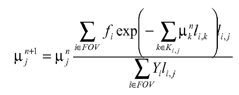
où
µn j est le coefficient d'atténuation au Jème pixel et à la nième itération,
fi est une valeur de balayage de référence au ième détecteur,
li,j est une longueur d'un segment d'un rayon s'étendant depuis le ième détecteur dans le jème pixel,
Ki,j est un ensemble de pixels depuis le jème détecteur jusqu'au ième détecteur, et
Yi est des comptes de transmission au ième détecteur. - Système selon la revendication 7, comprenant en outre :un moyen (100) pour compenser les données tronquées, lequel moyen de compensation (100) utilise une connaissance a priori pour reconfirmer les pixels se trouvant en dehors du champ de vision et forcer les pixels reconfirmés se trouvant en dehors du champ de vision à avoir des valeurs nulles dans l'image reconstruite.
- Système selon la revendication 1, comprenant en outre :au moins l'un d'un scanner PET et d'un scanner SPECT pour détecter des projections d'émission à partir du sujet.
- Procédé d'imagerie comprenant :la détection et la mesure d'au moins l'un d'un rayonnement d'émission et d'un rayonnement de transmission à partir d'un sujet selon une pluralité d'angles de projection ;la génération de données de projection mesurées selon la pluralité d'angles de projection ;la reconstruction de manière itérative du rayonnement détecté dans les représentations d'image dans une mémoire d'image, caractérisé par l'étape consistant à :déterminer une pluralité de pixels dans la représentation d'image reconstruite qui appartiennent à un champ de vision dans lequel le rayonnement est détecté par un détecteur de rayonnement à chaque angle de projection et que seul le rayonnement détecté dans le champ de vision est reconstruit de manière itérative dans des représentations d'image dans une mémoire d'image.
- Procédé selon la revendication 10, dans lequel l'étape de reconstruction comprend :la projection vers l'avant des représentations d'image ;la comparaison des représentations d'image projetées vers l'avant avec les données de projection mesurées ;sur la base de la comparaison, la détermination d'un ensemble de facteurs de correction ; etla projection vers l'arrière des facteurs de correction, qui correspondent seulement aux pixels dans le champ de vision déterminé, dans les représentations d'image.
- Procédé selon la revendication 11, dans lequel l'étape de reconstruction comprend en outre :la suppression des données se trouvant en dehors du champ de vision avant la projection vers l'arrière.
- Procédé selon la revendication 10, dans lequel l'étape de détermination du FOV comprend :la génération de balayages de référence.
- Procédé selon la revendication 10, comprenant en outre :la compensation de données tronquées par au moins l'une des manières suivantes :en fournissant une donnée non tronquée à partir des autres projections, eten utilisant une connaissance a priori.
- Procédé selon la revendication 10, dans lequel l'étape de reconstruction comprend l'exécution d'au moins l'un des algorithmes suivants :un algorithme itératif de gradient de reconstruction de la transmission ;un algorithme itératif sans gradient de reconstruction de la transmission ;un algorithme itératif de gradient de reconstruction de l'émission ;un algorithme itératif sans gradient de reconstruction de l'émission.
- Procédé selon la revendication 15, dans lequel l'étape de reconstruction comprend en outre :l'exécution d'un algorithme itératif de gradient de transmission, dans lequel les pixels se trouvant en dehors du champ de vision sont exclus de la reconstruction :

où
µn j est le coefficient d'atténuation au jème pixel et à la nième itération,
fi est une valeur de balayage de référence au ième détecteur,
li,j est une longueur d'un segment d'un rayon s'étendant depuis le ième détecteur dans le jème pixel,
Ki,j est un ensemble de pixels depuis le jème détecteur jusqu'au ième détecteur, et
Yi est des comptes de transmission au ième détecteur. - Procédé selon la revendication 16, comprenant en outre les étapes consistant à :reconfirmer les pixels se trouvant en dehors du champ de vision en utilisant une connaissance a priori, etforcer les pixels reconfirmés se trouvant en dehors du champ de vision à avoir des valeurs nulles dans l'image reconstruite.
Applications Claiming Priority (2)
| Application Number | Priority Date | Filing Date | Title |
|---|---|---|---|
| US63718604P | 2004-12-17 | 2004-12-17 | |
| PCT/IB2005/054070 WO2006064404A2 (fr) | 2004-12-17 | 2005-12-05 | Algorithme de compensation de troncature pour reconstruction iterative |
Publications (2)
| Publication Number | Publication Date |
|---|---|
| EP1828808A2 EP1828808A2 (fr) | 2007-09-05 |
| EP1828808B1 true EP1828808B1 (fr) | 2010-04-21 |
Family
ID=36168839
Family Applications (1)
| Application Number | Title | Priority Date | Filing Date |
|---|---|---|---|
| EP05824462A Expired - Lifetime EP1828808B1 (fr) | 2004-12-17 | 2005-12-05 | Algorithme de compensation de troncature pour reconstruction iterative |
Country Status (7)
| Country | Link |
|---|---|
| US (1) | US8013307B2 (fr) |
| EP (1) | EP1828808B1 (fr) |
| JP (1) | JP4731571B2 (fr) |
| CN (1) | CN101080651B (fr) |
| AT (1) | ATE465425T1 (fr) |
| DE (1) | DE602005020844D1 (fr) |
| WO (1) | WO2006064404A2 (fr) |
Families Citing this family (19)
| Publication number | Priority date | Publication date | Assignee | Title |
|---|---|---|---|---|
| CN101405619B (zh) * | 2006-03-16 | 2013-01-02 | 皇家飞利浦电子股份有限公司 | 计算机断层造影数据采集装置和方法 |
| US8335358B2 (en) * | 2007-03-29 | 2012-12-18 | Palodex Group Oy | Method and system for reconstructing a medical image of an object |
| WO2010032168A2 (fr) * | 2008-09-19 | 2010-03-25 | Koninklijke Philips Electronics N.V. | Procédé pour la génération de carte d’atténuation dans la résonance magnétique et la tépographie |
| US8299438B2 (en) * | 2009-07-16 | 2012-10-30 | Siemens Medical Solutions Usa, Inc. | Model based estimation of a complete or partial positron emission tomography attenuation map using maximum likelihood expectation maximization |
| JP5662447B2 (ja) | 2009-08-20 | 2015-01-28 | コーニンクレッカ フィリップス エヌ ヴェ | 関心領域画像の再構成 |
| US9053569B2 (en) * | 2010-11-04 | 2015-06-09 | Siemens Medical Solutions Usa, Inc. | Generating attenuation correction maps for combined modality imaging studies and improving generated attenuation correction maps using MLAA and DCC algorithms |
| RU2606561C2 (ru) | 2011-01-27 | 2017-01-10 | Конинклейке Филипс Электроникс Н.В. | Компенсация усечения для итерационной реконструкции в компьютерной томографии (кт) с коническим пучком в комбинированных системах офэкт/кт |
| DE102011075912A1 (de) * | 2011-05-16 | 2012-11-22 | Siemens Ag | Verfahren zum Bereitstellen eines 3D-Bilddatensatzes mit unterdrückten Bildartefakten und Computertomograph |
| JP2015504515A (ja) * | 2011-11-22 | 2015-02-12 | コーニンクレッカ フィリップス エヌ ヴェ | ガントリのないspectシステム |
| US9135695B2 (en) * | 2012-04-04 | 2015-09-15 | Siemens Aktiengesellschaft | Method for creating attenuation correction maps for PET image reconstruction |
| CN103961123B (zh) * | 2013-01-31 | 2018-11-06 | Ge医疗系统环球技术有限公司 | 计算机断层摄影(ct)方法和ct系统 |
| US11838851B1 (en) | 2014-07-15 | 2023-12-05 | F5, Inc. | Methods for managing L7 traffic classification and devices thereof |
| CN107077724B (zh) | 2014-10-20 | 2022-03-29 | 皇家飞利浦有限公司 | 分类的截断补偿 |
| US10182013B1 (en) | 2014-12-01 | 2019-01-15 | F5 Networks, Inc. | Methods for managing progressive image delivery and devices thereof |
| US9713450B2 (en) * | 2014-12-15 | 2017-07-25 | General Electric Company | Iterative reconstruction of projection data |
| US11895138B1 (en) | 2015-02-02 | 2024-02-06 | F5, Inc. | Methods for improving web scanner accuracy and devices thereof |
| CN109961491B (zh) | 2019-04-12 | 2023-05-26 | 上海联影医疗科技股份有限公司 | 多模态图像截断补偿方法、装置、计算机设备和介质 |
| CN113269733B (zh) * | 2021-05-14 | 2024-04-16 | 成都真实维度科技有限公司 | 一种断层扫描图像中放射粒子的伪影检测方法 |
| CN114419173B (zh) * | 2021-12-01 | 2024-11-08 | 广州华端科技有限公司 | 三维x射线成像系统截断伪影校正方法及装置 |
Family Cites Families (12)
| Publication number | Priority date | Publication date | Assignee | Title |
|---|---|---|---|---|
| US5210421A (en) * | 1991-06-10 | 1993-05-11 | Picker International, Inc. | Simultaneous transmission and emission converging tomography |
| FR2736163B1 (fr) * | 1995-06-29 | 1997-08-22 | Sopha Medical | Methode d'obtention, en medecine nucleaire, d'une image du corps d'un patient corrigee des troncatures |
| US6539103B1 (en) * | 1997-11-12 | 2003-03-25 | The University Of Utah | Method and apparatus for image reconstruction using a knowledge set |
| JPH11298380A (ja) * | 1998-04-08 | 1999-10-29 | Nec Saitama Ltd | クロック生成回路 |
| IL126761A0 (en) | 1998-10-26 | 1999-08-17 | Romidot Ltd | Computerized tomography for non-destructive testing |
| US6310968B1 (en) * | 1998-11-24 | 2001-10-30 | Picker International, Inc. | Source-assisted attenuation correction for emission computed tomography |
| US6490476B1 (en) * | 1999-10-14 | 2002-12-03 | Cti Pet Systems, Inc. | Combined PET and X-ray CT tomograph and method for using same |
| GB0128361D0 (en) * | 2001-11-27 | 2002-01-16 | British Nuclear Fuels Plc | Improvements in and relating to instruments |
| US20030190065A1 (en) * | 2002-03-26 | 2003-10-09 | Cti Pet Systems, Inc. | Fast iterative image reconstruction from linograms |
| US6856666B2 (en) * | 2002-10-04 | 2005-02-15 | Ge Medical Systems Global Technology Company, Llc | Multi modality imaging methods and apparatus |
| US6768782B1 (en) * | 2002-12-16 | 2004-07-27 | University Of Notre Dame Du Lac | Iterative method for region-of-interest reconstruction |
| US7173248B2 (en) * | 2004-10-20 | 2007-02-06 | General Electric Company | Methods and systems for positron emission tomography data correction |
-
2005
- 2005-12-05 EP EP05824462A patent/EP1828808B1/fr not_active Expired - Lifetime
- 2005-12-05 WO PCT/IB2005/054070 patent/WO2006064404A2/fr not_active Ceased
- 2005-12-05 JP JP2007546239A patent/JP4731571B2/ja not_active Expired - Fee Related
- 2005-12-05 US US11/721,722 patent/US8013307B2/en active Active
- 2005-12-05 AT AT05824462T patent/ATE465425T1/de not_active IP Right Cessation
- 2005-12-05 CN CN2005800433609A patent/CN101080651B/zh not_active Expired - Fee Related
- 2005-12-05 DE DE602005020844T patent/DE602005020844D1/de not_active Expired - Lifetime
Also Published As
| Publication number | Publication date |
|---|---|
| JP2008524575A (ja) | 2008-07-10 |
| CN101080651A (zh) | 2007-11-28 |
| US8013307B2 (en) | 2011-09-06 |
| EP1828808A2 (fr) | 2007-09-05 |
| CN101080651B (zh) | 2010-06-16 |
| JP4731571B2 (ja) | 2011-07-27 |
| WO2006064404A2 (fr) | 2006-06-22 |
| DE602005020844D1 (de) | 2010-06-02 |
| ATE465425T1 (de) | 2010-05-15 |
| US20090310746A1 (en) | 2009-12-17 |
| WO2006064404A3 (fr) | 2006-08-31 |
Similar Documents
| Publication | Publication Date | Title |
|---|---|---|
| EP1828808B1 (fr) | Algorithme de compensation de troncature pour reconstruction iterative | |
| US6310968B1 (en) | Source-assisted attenuation correction for emission computed tomography | |
| EP1934942B1 (fr) | Reconstruction iterative a filtrage ameliore pour le control du bruit | |
| US5565684A (en) | Three-dimensional SPECT reconstruction of combined cone-beam and fan-beam data | |
| US6381349B1 (en) | Projector/backprojector with slice-to-slice blurring for efficient 3D scatter modeling | |
| EP2210238B1 (fr) | Appareil et procédé pour générer une carte d'atténuation | |
| EP1828977B1 (fr) | Restauration d'une image planaire 2d de medecine nucleaire par une deconvolution iterative contrainte | |
| US10126439B2 (en) | Reconstruction with multiple photopeaks in quantitative single photon emission computed tomography | |
| EP2454721B1 (fr) | Reconstitution d image avec compensation du flou variant en décalage | |
| US6539103B1 (en) | Method and apparatus for image reconstruction using a knowledge set | |
| US7675038B2 (en) | Truncation compensation in transmission reconstructions for a small FOV cardiac gamma camera | |
| Beekman et al. | Improvement of image resolution and quantitative accuracy in clinical single photon emission computed tomography | |
| JP4298297B2 (ja) | 診断用撮像装置及び画像処理方法 | |
| US7890282B2 (en) | Estimation of crystal efficiency with axially compressed sinogram | |
| Han | Image reconstruction in quantitaive cardiac SPECT with varying focal-length fan-beam collimators | |
| Kalki et al. | Myocardial perfusion imaging with a correlated X-ray CT and SPECT system: An animal study | |
| Wong et al. | Development of quantitative imaging methods for the GE Hawkeye CT/SPECT system | |
| Liu | A comprehensive method for quantitative cardiac SPECT | |
| Ye | Quantitative technetium-99m myocardial perfusion SPECT with 180 degree acquisition | |
| Mao | Segmented parallel and slant-hole stationary cardiac single photon emission computed tomography |
Legal Events
| Date | Code | Title | Description |
|---|---|---|---|
| PUAI | Public reference made under article 153(3) epc to a published international application that has entered the european phase |
Free format text: ORIGINAL CODE: 0009012 |
|
| 17P | Request for examination filed |
Effective date: 20070717 |
|
| AK | Designated contracting states |
Kind code of ref document: A2 Designated state(s): AT BE BG CH CY CZ DE DK EE ES FI FR GB GR HU IE IS IT LI LT LU LV MC NL PL PT RO SE SI SK TR |
|
| DAX | Request for extension of the european patent (deleted) | ||
| 17Q | First examination report despatched |
Effective date: 20080310 |
|
| GRAP | Despatch of communication of intention to grant a patent |
Free format text: ORIGINAL CODE: EPIDOSNIGR1 |
|
| GRAS | Grant fee paid |
Free format text: ORIGINAL CODE: EPIDOSNIGR3 |
|
| GRAA | (expected) grant |
Free format text: ORIGINAL CODE: 0009210 |
|
| AK | Designated contracting states |
Kind code of ref document: B1 Designated state(s): AT BE BG CH CY CZ DE DK EE ES FI FR GB GR HU IE IS IT LI LT LU LV MC NL PL PT RO SE SI SK TR |
|
| REG | Reference to a national code |
Ref country code: GB Ref legal event code: FG4D |
|
| REG | Reference to a national code |
Ref country code: CH Ref legal event code: EP |
|
| REG | Reference to a national code |
Ref country code: IE Ref legal event code: FG4D |
|
| REF | Corresponds to: |
Ref document number: 602005020844 Country of ref document: DE Date of ref document: 20100602 Kind code of ref document: P |
|
| REG | Reference to a national code |
Ref country code: NL Ref legal event code: VDEP Effective date: 20100421 |
|
| LTIE | Lt: invalidation of european patent or patent extension |
Effective date: 20100421 |
|
| PG25 | Lapsed in a contracting state [announced via postgrant information from national office to epo] |
Ref country code: SE Free format text: LAPSE BECAUSE OF FAILURE TO SUBMIT A TRANSLATION OF THE DESCRIPTION OR TO PAY THE FEE WITHIN THE PRESCRIBED TIME-LIMIT Effective date: 20100421 Ref country code: NL Free format text: LAPSE BECAUSE OF FAILURE TO SUBMIT A TRANSLATION OF THE DESCRIPTION OR TO PAY THE FEE WITHIN THE PRESCRIBED TIME-LIMIT Effective date: 20100421 Ref country code: ES Free format text: LAPSE BECAUSE OF FAILURE TO SUBMIT A TRANSLATION OF THE DESCRIPTION OR TO PAY THE FEE WITHIN THE PRESCRIBED TIME-LIMIT Effective date: 20100801 Ref country code: LT Free format text: LAPSE BECAUSE OF FAILURE TO SUBMIT A TRANSLATION OF THE DESCRIPTION OR TO PAY THE FEE WITHIN THE PRESCRIBED TIME-LIMIT Effective date: 20100421 |
|
| PG25 | Lapsed in a contracting state [announced via postgrant information from national office to epo] |
Ref country code: LV Free format text: LAPSE BECAUSE OF FAILURE TO SUBMIT A TRANSLATION OF THE DESCRIPTION OR TO PAY THE FEE WITHIN THE PRESCRIBED TIME-LIMIT Effective date: 20100421 Ref country code: AT Free format text: LAPSE BECAUSE OF FAILURE TO SUBMIT A TRANSLATION OF THE DESCRIPTION OR TO PAY THE FEE WITHIN THE PRESCRIBED TIME-LIMIT Effective date: 20100421 Ref country code: FI Free format text: LAPSE BECAUSE OF FAILURE TO SUBMIT A TRANSLATION OF THE DESCRIPTION OR TO PAY THE FEE WITHIN THE PRESCRIBED TIME-LIMIT Effective date: 20100421 Ref country code: IS Free format text: LAPSE BECAUSE OF FAILURE TO SUBMIT A TRANSLATION OF THE DESCRIPTION OR TO PAY THE FEE WITHIN THE PRESCRIBED TIME-LIMIT Effective date: 20100821 Ref country code: SI Free format text: LAPSE BECAUSE OF FAILURE TO SUBMIT A TRANSLATION OF THE DESCRIPTION OR TO PAY THE FEE WITHIN THE PRESCRIBED TIME-LIMIT Effective date: 20100421 |
|
| PG25 | Lapsed in a contracting state [announced via postgrant information from national office to epo] |
Ref country code: PL Free format text: LAPSE BECAUSE OF FAILURE TO SUBMIT A TRANSLATION OF THE DESCRIPTION OR TO PAY THE FEE WITHIN THE PRESCRIBED TIME-LIMIT Effective date: 20100421 Ref country code: GR Free format text: LAPSE BECAUSE OF FAILURE TO SUBMIT A TRANSLATION OF THE DESCRIPTION OR TO PAY THE FEE WITHIN THE PRESCRIBED TIME-LIMIT Effective date: 20100722 Ref country code: CY Free format text: LAPSE BECAUSE OF FAILURE TO SUBMIT A TRANSLATION OF THE DESCRIPTION OR TO PAY THE FEE WITHIN THE PRESCRIBED TIME-LIMIT Effective date: 20100512 |
|
| PG25 | Lapsed in a contracting state [announced via postgrant information from national office to epo] |
Ref country code: PT Free format text: LAPSE BECAUSE OF FAILURE TO SUBMIT A TRANSLATION OF THE DESCRIPTION OR TO PAY THE FEE WITHIN THE PRESCRIBED TIME-LIMIT Effective date: 20100823 Ref country code: DK Free format text: LAPSE BECAUSE OF FAILURE TO SUBMIT A TRANSLATION OF THE DESCRIPTION OR TO PAY THE FEE WITHIN THE PRESCRIBED TIME-LIMIT Effective date: 20100421 Ref country code: EE Free format text: LAPSE BECAUSE OF FAILURE TO SUBMIT A TRANSLATION OF THE DESCRIPTION OR TO PAY THE FEE WITHIN THE PRESCRIBED TIME-LIMIT Effective date: 20100421 |
|
| PLBE | No opposition filed within time limit |
Free format text: ORIGINAL CODE: 0009261 |
|
| STAA | Information on the status of an ep patent application or granted ep patent |
Free format text: STATUS: NO OPPOSITION FILED WITHIN TIME LIMIT |
|
| PG25 | Lapsed in a contracting state [announced via postgrant information from national office to epo] |
Ref country code: CZ Free format text: LAPSE BECAUSE OF FAILURE TO SUBMIT A TRANSLATION OF THE DESCRIPTION OR TO PAY THE FEE WITHIN THE PRESCRIBED TIME-LIMIT Effective date: 20100421 Ref country code: RO Free format text: LAPSE BECAUSE OF FAILURE TO SUBMIT A TRANSLATION OF THE DESCRIPTION OR TO PAY THE FEE WITHIN THE PRESCRIBED TIME-LIMIT Effective date: 20100421 Ref country code: SK Free format text: LAPSE BECAUSE OF FAILURE TO SUBMIT A TRANSLATION OF THE DESCRIPTION OR TO PAY THE FEE WITHIN THE PRESCRIBED TIME-LIMIT Effective date: 20100421 Ref country code: BE Free format text: LAPSE BECAUSE OF FAILURE TO SUBMIT A TRANSLATION OF THE DESCRIPTION OR TO PAY THE FEE WITHIN THE PRESCRIBED TIME-LIMIT Effective date: 20100421 |
|
| 26N | No opposition filed |
Effective date: 20110124 |
|
| PG25 | Lapsed in a contracting state [announced via postgrant information from national office to epo] |
Ref country code: IT Free format text: LAPSE BECAUSE OF FAILURE TO SUBMIT A TRANSLATION OF THE DESCRIPTION OR TO PAY THE FEE WITHIN THE PRESCRIBED TIME-LIMIT Effective date: 20100421 |
|
| PG25 | Lapsed in a contracting state [announced via postgrant information from national office to epo] |
Ref country code: MC Free format text: LAPSE BECAUSE OF NON-PAYMENT OF DUE FEES Effective date: 20101231 |
|
| REG | Reference to a national code |
Ref country code: CH Ref legal event code: PL |
|
| PG25 | Lapsed in a contracting state [announced via postgrant information from national office to epo] |
Ref country code: CH Free format text: LAPSE BECAUSE OF NON-PAYMENT OF DUE FEES Effective date: 20101231 Ref country code: IE Free format text: LAPSE BECAUSE OF NON-PAYMENT OF DUE FEES Effective date: 20101205 Ref country code: LI Free format text: LAPSE BECAUSE OF NON-PAYMENT OF DUE FEES Effective date: 20101231 |
|
| PG25 | Lapsed in a contracting state [announced via postgrant information from national office to epo] |
Ref country code: LU Free format text: LAPSE BECAUSE OF NON-PAYMENT OF DUE FEES Effective date: 20101205 Ref country code: BG Free format text: LAPSE BECAUSE OF FAILURE TO SUBMIT A TRANSLATION OF THE DESCRIPTION OR TO PAY THE FEE WITHIN THE PRESCRIBED TIME-LIMIT Effective date: 20100421 Ref country code: HU Free format text: LAPSE BECAUSE OF FAILURE TO SUBMIT A TRANSLATION OF THE DESCRIPTION OR TO PAY THE FEE WITHIN THE PRESCRIBED TIME-LIMIT Effective date: 20101022 |
|
| PG25 | Lapsed in a contracting state [announced via postgrant information from national office to epo] |
Ref country code: TR Free format text: LAPSE BECAUSE OF FAILURE TO SUBMIT A TRANSLATION OF THE DESCRIPTION OR TO PAY THE FEE WITHIN THE PRESCRIBED TIME-LIMIT Effective date: 20100421 |
|
| PG25 | Lapsed in a contracting state [announced via postgrant information from national office to epo] |
Ref country code: BG Free format text: LAPSE BECAUSE OF FAILURE TO SUBMIT A TRANSLATION OF THE DESCRIPTION OR TO PAY THE FEE WITHIN THE PRESCRIBED TIME-LIMIT Effective date: 20100721 |
|
| REG | Reference to a national code |
Ref country code: DE Ref legal event code: R082 Ref document number: 602005020844 Country of ref document: DE Representative=s name: MEISSNER, BOLTE & PARTNER GBR, DE |
|
| REG | Reference to a national code |
Ref country code: DE Ref legal event code: R082 Ref document number: 602005020844 Country of ref document: DE Representative=s name: MEISSNER, BOLTE & PARTNER GBR, DE Effective date: 20140328 Ref country code: DE Ref legal event code: R082 Ref document number: 602005020844 Country of ref document: DE Representative=s name: MEISSNER BOLTE PATENTANWAELTE RECHTSANWAELTE P, DE Effective date: 20140328 Ref country code: DE Ref legal event code: R081 Ref document number: 602005020844 Country of ref document: DE Owner name: KONINKLIJKE PHILIPS N.V., NL Free format text: FORMER OWNER: KONINKLIJKE PHILIPS ELECTRONICS N.V., EINDHOVEN, NL Effective date: 20140328 |
|
| REG | Reference to a national code |
Ref country code: FR Ref legal event code: CD Owner name: KONINKLIJKE PHILIPS ELECTRONICS N.V., NL Effective date: 20141126 Ref country code: FR Ref legal event code: CA Effective date: 20141126 |
|
| REG | Reference to a national code |
Ref country code: FR Ref legal event code: PLFP Year of fee payment: 11 |
|
| REG | Reference to a national code |
Ref country code: FR Ref legal event code: PLFP Year of fee payment: 12 |
|
| PGFP | Annual fee paid to national office [announced via postgrant information from national office to epo] |
Ref country code: FR Payment date: 20161229 Year of fee payment: 12 |
|
| REG | Reference to a national code |
Ref country code: FR Ref legal event code: ST Effective date: 20180831 |
|
| PG25 | Lapsed in a contracting state [announced via postgrant information from national office to epo] |
Ref country code: FR Free format text: LAPSE BECAUSE OF NON-PAYMENT OF DUE FEES Effective date: 20180102 |
|
| PGFP | Annual fee paid to national office [announced via postgrant information from national office to epo] |
Ref country code: GB Payment date: 20211221 Year of fee payment: 17 |
|
| GBPC | Gb: european patent ceased through non-payment of renewal fee |
Effective date: 20221205 |
|
| PG25 | Lapsed in a contracting state [announced via postgrant information from national office to epo] |
Ref country code: GB Free format text: LAPSE BECAUSE OF NON-PAYMENT OF DUE FEES Effective date: 20221205 |
|
| REG | Reference to a national code |
Ref country code: DE Ref legal event code: R084 Ref document number: 602005020844 Country of ref document: DE |
|
| PGFP | Annual fee paid to national office [announced via postgrant information from national office to epo] |
Ref country code: DE Payment date: 20231227 Year of fee payment: 19 |
|
| REG | Reference to a national code |
Ref country code: DE Ref legal event code: R119 Ref document number: 602005020844 Country of ref document: DE |
|
| PG25 | Lapsed in a contracting state [announced via postgrant information from national office to epo] |
Ref country code: DE Free format text: LAPSE BECAUSE OF NON-PAYMENT OF DUE FEES Effective date: 20250701 |