EP1829650B1 - Dispositif de main robot - Google Patents
Dispositif de main robot Download PDFInfo
- Publication number
- EP1829650B1 EP1829650B1 EP05788043A EP05788043A EP1829650B1 EP 1829650 B1 EP1829650 B1 EP 1829650B1 EP 05788043 A EP05788043 A EP 05788043A EP 05788043 A EP05788043 A EP 05788043A EP 1829650 B1 EP1829650 B1 EP 1829650B1
- Authority
- EP
- European Patent Office
- Prior art keywords
- axis
- link
- robot hand
- finger
- hole
- Prior art date
- Legal status (The legal status is an assumption and is not a legal conclusion. Google has not performed a legal analysis and makes no representation as to the accuracy of the status listed.)
- Expired - Lifetime
Links
Images





Classifications
-
- B—PERFORMING OPERATIONS; TRANSPORTING
- B25—HAND TOOLS; PORTABLE POWER-DRIVEN TOOLS; MANIPULATORS
- B25J—MANIPULATORS; CHAMBERS PROVIDED WITH MANIPULATION DEVICES
- B25J15/00—Gripping heads and other end effectors
- B25J15/0009—Gripping heads and other end effectors comprising multi-articulated fingers, e.g. resembling a human hand
-
- B—PERFORMING OPERATIONS; TRANSPORTING
- B25—HAND TOOLS; PORTABLE POWER-DRIVEN TOOLS; MANIPULATORS
- B25J—MANIPULATORS; CHAMBERS PROVIDED WITH MANIPULATION DEVICES
- B25J15/00—Gripping heads and other end effectors
- B25J15/02—Gripping heads and other end effectors servo-actuated
-
- B—PERFORMING OPERATIONS; TRANSPORTING
- B25—HAND TOOLS; PORTABLE POWER-DRIVEN TOOLS; MANIPULATORS
- B25J—MANIPULATORS; CHAMBERS PROVIDED WITH MANIPULATION DEVICES
- B25J15/00—Gripping heads and other end effectors
- B25J15/08—Gripping heads and other end effectors having finger members
-
- B—PERFORMING OPERATIONS; TRANSPORTING
- B25—HAND TOOLS; PORTABLE POWER-DRIVEN TOOLS; MANIPULATORS
- B25J—MANIPULATORS; CHAMBERS PROVIDED WITH MANIPULATION DEVICES
- B25J9/00—Program-controlled manipulators
- B25J9/16—Program controls
- B25J9/1612—Program controls characterised by the hand, wrist, grip control
Definitions
- the present invention relates to a robot hand apparatus which can actuate a finger around two cross-axes crossing each other.
- two crossing axes are required, if it is assumed a palm is facing upside (see Japanese unexamined patent publication JP No. 2003-117873 ).
- one of two crossing axes is an axis for rotating a thumb in a height direction
- the other of two crossing axes is an axis for rotating the thumb in a left-and-right direction.
- Patent document JP 2001 347 482 A discloses a robot hand apparatus according to the preamble of claim 1.
- the present invention relates to a robot hand apparatus, which has a base, a motor, a first-link, a second link, and a finger link.
- the motor is fixed to the base, and the first-link is supported by the base while allowing the rotation around a first axis, and has a first guide path in which a control axis is movable.
- the first axis is an axis in parallel to an actuation axis of the motor and is positioned apart from the actuation axis.
- the second link connects with the actuation axis of the motor and supports the control axis.
- the second link moves the control axis within the first guide path in accordance with the rotation of the actuation axis of the motor, and the finger link is supported by the first link while allowing the rotation around a second axis crossing the first axis.
- the finger link directly or indirectly links with the control axis so that the finger link is rotated around the second axis in accordance with the actuation of the control axis.
- finger link can be rotated around two crossing axes using a single motor, the motor, the reduction unit, and the motor driver are not required for each axis.
- the base has a second guide path within the moveable range of the first guide path
- the second link includes a rotator, which is fixed to the actuation axis, and a connection link, which is rotatably supported by the rotator and supports the control axis.
- the first link and the finger link can be actuated separately.
- the finger link can be actuated after the actuation of the first link.
- the second guide path is formed by connecting a first guide hole and a second guide hole.
- the first guide hole is formed by elongating in a circumference direction around the first axis, and that the first guide hole guides the control axis in a circumference direction around the first axis.
- the second guide hole is formed by elongating in a radial direction with respect to the first axis, and that the second guide hole guides the first axis in a radial direction.
- the first link can be actuated around first axis by the fist guide hole, and the finger link can be actuated around the second axis by the second guide hole.
- control axis is adapted to slide within the first guide hole and the second guide hole.
- the finger link can be actuated smoothly and constantly on a constant locus.
- the finger link can be actuated around two axes using a simple mechanism, the reduction of the number of the parts can be achieved.
- the robot hand apparatus of the present invention is suitable for the use in a humanoid-type robot.
- the robot hand apparatus 1 of the present embodiment relates to the construction about the finger which corresponds to a thumb of a human.
- the robot hand apparatus 1 is provided to each arm R3. But, in the following explanation, the explanation is carried out about the robot hand apparatus 1 installed on the right hand, and the explanation about that of installed on the left hand will be omitted. This is because the left hand is symmetrical with respect to the right hand.
- the robot hand apparatus 1 of the present embodiment is provided at an end of the arm R3 of a bipedal waling robot R.
- This robot R has two legs R1, a body R2, two arms R3, and a head R4, like a human.
- the leg R1 and arm R3 disposed on a right side of the robot R is not shown.
- the head R4 has cameras, microphone, and speaker, which are omitted in this figure.
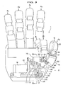
- the robot hand apparatus 1 has a five fingers Fa, Fb, Fc, Fd, and Fe, like a human.
- a finger link F1 is installed on the finger Fa, which corresponds to a thumb of a human, and is allowed to change the posture between posture A, posture C, and posture B.
- the posture A and posture B are respectively indicated using a dot dash line.
- the posture A is the condition where the finger link F1 is flexed inside and is in the vicinity of the palm section.
- the posture B is the condition where the finger link F1 is flexed inside and is separated from the palm section.
- the posture C is the condition where the finger link F1 is stretched and is in the outside than the posture B.
- each of the remaining fingers Fb -Fe is provided with a first joint and a second joint and is actuated by other motor (not shown) and a link mechanism so as to change the posture between a stretched posture and a hunched posture.
- FIG.2 the case where each of the fingers Fb-Fe is in a stretched posture is shown in FIG.2 .
- the robot hand apparatus 1 has the finger link F1, a motor M, a first link 10, and a second link 20.
- the finger link F1 of the present embodiment consists of a finger base 50, a finger tip 51, a cover 52, and a cover 53.
- the finger tip 51 rotatably connects with the tip of the finger base 50.
- the cover 52 and the cover 53 cover the periphery of the finger base 50 and the finger tip 51, respectively, and has a shape of a finger (see FIG.3 ).
- the motor M is fixed to a base 2, which is a plate-like shaped member, through a reduction unit G.
- This base 2 is fixed to a base stage S provided on a wrist of the arm R3.
- a motor base 5, to which the motor M is fixed is fixed to the base stage S, and the reduction unit G is fixed to the base 2 and motor base 5 through a screw.
- the motor M is fixed to the region in a direction X1 side of the base 2, and an actuation shaft g, which connects with an output shaft (not shown) of the motor M through the reduction unit G, elongates in a direction X2 side.
- a rotation hole 2a and a second guide path 2b each penetrates in a direction parallel to the line X1-X2, are provided on the base 2.
- the position where the second guide path 2b is provided is in the vicinity of the rotation hole 2a.
- the line X1-X2 is in parallel to the output shaft of the motor M.
- the second guide path 2b comprises a second guide hole 2b2, which is a curved hole elongating in a circumference direction around the rotation hole 2a, and a first guide hole 2b1, which is a straight long hole elongating in a radial direction.
- the second guide path 2b is formed by joining the first guide hole 2b1 and the second guide hole 2b2.
- the first link 10 is obtained by combining into an integral body a pair of legs 11 and 12 and a pair of guide plates 13 and 14.
- Each of legs 11 and 12 is disposed in parallel to the base 2 and each of legs 11 and 12 is an elongated plate.
- the base end of the leg 11 and 12 is provided with a hole 11a and 12a and a guide long hole (a first guide path) 11b and 12b respectively.
- a predetermined interval is provided between the hole 11a (12a) and the guide long hole 11b (12b).
- leg 11 and 12 are disposed in parallel in a direction along the line X1-X2.
- connection hole 13a and 14a is formed at a corner in an direction X2 side of the guide plate 13 and 14.
- a clearance 15 with a predetermined width is formed between the side-surface 12c of leg 12 and the edge 13b and 14b of the guide plate 13 and 14.
- the second link 20 consists of a rotator 21 and a connection link 22.
- the rotator 21 is a disk-like shaped member and is disposed in parallel to the base 2.
- a driven hole 21a which serves as a rotation center, and a connection hole 21b are formed on the rotator 21.
- the position where the connection hole 21b is formed is the eccentric position with respect to the driven hole 21a.
- a protrusion 21c having a sector shape is provided on the rotator 21 and is formed into an integral shape with the rotator 21.
- the position where the protrusion 21c is provided is the position opposite across the driven hole 21a with regard to the connection hole 21b.
- connection link 22 has a long link plate 22a, which has a through hole 22a1 at one end thereof and has a connection hole 22a2 at the other end thereof, and a short link plate 22b, which has a through hole 22b1 being coaxial with respect to the through hole 22a1.
- the long link plate 22a and the short link plate 22b are disposed in parallel in a direction along the line X1-X2 by the connection plate 22c so that a predetermined interval is secured therebetween.
- a elevating member 30 is provided on the connection link 22.
- the elevating member 30 has a side plate 30a, which faces a direction along the line X1-X2, a pair of side plates 30b and 30b orthogonal to the side plate 30a, and a bottom plate 30c (see FIG. 7 ).
- a rectangular shaped space Q is formed inside of the elevating member 30.
- the side plate 30a is provided with a connection hole 30a1
- the side plate 30b and 30b is provided with a pin connection hole 30b1 and 30b1.
- the distance between side plates 30b of the elevating member 30 is established so that the elevating member 30 can slide between the guide plate 13 and the guide plate 14.
- An arm member 31 is provided to the elevating member 30.
- the width of the arm member 31 is established so that the arm member 31 can be inserted between the side plates 30b and 30b, and one end of the arm member 31 is curved to a direction X2 side.
- the arm member 31 is provided with pin holes 31a and 31b, which are in parallel to the pin connection hole 30b1, at base end and tip thereof.
- the finger base 50 which constitutes a part of the finger link F1 has a pair of connection sections 50a and 50a.
- the connection sections 50a and 50a are disposed with an interval therebetween so that the insertion to this interval of the arm member 31 is enabled.
- connection section 50a is provided with a pin connection hole 50a1 which is in parallel to the pin hole 31b, and a connection hole 50a2 which is in parallel to the connection hole 13a and 14a is provided in the vicinity of the pin connection hole 50a1.
- connection hole 50a2 disposed on one of the connection sections 50a is not shown in FIG.4 .
- a bearing 60 which can slide within the second guide path 2b is provided.
- the bearing 60 is obtained by sandwiching a plurality of balls, which are aligned along a periphery direction while allowing the rotation, between an inside ring (not shown) and an outside ring (not shown).
- the bearing 60 is adapted to move the inside of the second guide path 2b while keeping the contact between the circumference thereof with the inside circumference of the second guide path 2b.
- dropout prevention means (not shown) is provided on a control axis 42 or the base 2 for preventing the dropout of the bearing 60 from the second guide path 2b.
- the first link 10 connects with the base 2 through a rigid axis 40. That is, after disposing the first link 10 so that the base 2 is positioned between the leg 11 and the leg 12, the rigid axis 40 is inserted from a direction X1 side in order of: the hole 11a, the rotation hole 2a, and the hole 12a. Thereby, the first link 10 connects with the base 2 while allowing the rotation around the rigid axis 40.
- the rotation center of the first link 10 serves as a first axis S1 (see FIG.2 and FIG.3 ).
- connection link 22 becomes rotatable with respect to the rotator 21.
- connection link 22 After disposing the connection link 22 so that leg 12 is positioned between the long link plate 22a and the short link plate 22b, which are provided to the connection link 22, the first link 10 and the second link 20 are connected each other by the control axis 42.
- the control axis 42 is inserted from a direction X1 side in order of: guide long hole 11b of the leg 11, the second guide path 2b of the base 2, the bearing 60, the through hole 22b1 of the short link plate 22b1, the long hole 12b of the leg 12, the through hole 22a1 of the long link plate 22a, and the connection hole 30a1 of the elevating member 30.
- the first link 10 and the connection link 22 of the second link 20 are joined each other.
- control axis 42 is guided by long holes 11b and 12b and the second guide path 2b, and the elevating member 30 moves between the guide plate 13 and the guide plate 14 while rotating with respect to the connection link 22.
- the a pin 43 is inserted into the pin connection hole 30b1 and 30b1 of the elevating member 30 and the pin hole 31a of the arm member 31, under the condition the base end of the arm member 31 is inserted into the space Q of the elevating member 30.
- the arm member 31 rotetably connects with the elevating member 30.
- a pin 44 is inserted into the pin hole 31b of the arm member 31 and the pin connection hole 50a1 and 50a1 of the connection section 50a and 50a, under the condition the tip of the arm member 31 is inserted between the connection sections 50a and 50a of the finger link F1. Thereby, the arm member 31 is rotateably connects with the finger link F1.
- connection pin 45 is inserted into the connection hole 50a2 and 50a2 (one of them is not shown) of the connection section 50a and 50a and connection hole 13a and 14a of the guide plate 13 and 14, under the condition the connection section 50a and 50a of the finger link F1 is inserted between the guide plates 13 and 14 of the first link 10.
- the finger link F1 is rotatably connects with the first link 10.
- the finger link F1 changes the posture between posture A, posture C, and posture B, under the condition where the palm section is facing an upside.
- the posture A is the condition where the finger link F1 is flexed inside and is in the vicinity of the palm section.
- the posture B is the condition where the finger link F1 was rotated, from posture A, around the first axis S1 (see FIG.2 and FIG.3 ) to an upper direction separating from the palm section.
- the posture C is the condition where the finger link F1 was rotated, from posture B, around the second axis S2 to the outside.
- the finger link F1 slightly turns outside around the second axis S2 (see FIG.2 and FIG.3 ), during the change of the posture from posture A to posture B.
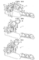
- FIGS 5A to 5C the indication of the arm member 31 to be connected to the elevating member 30, the finger base 50 to be connected to this arm member 31, and the finger tip 51 is omitted.
- the posture A shown in FIG.5A is the condition where the rotator 21 was fully rotated in a clockwise direction around the actuation shaft g.
- the control axis 42 is positioned within the first guide hole 2b1 of the second guide path 2b, and is in the vicinity of a base side (a rigid axis 40 side) of the guide long hole 11b of the leg 11.
- the control axis 42 is positioned in the guide long hole 12b at almost the same position as the position within the guide long hole 11b of the control axis 42.
- the first link 10 rotates in a clockwise direction around the rigid axis 40 which serves as the first axis S1 as the supporting point.
- the finger link F1 is flexed in compliance with the flexing of the first link 10. Additionally, due to the flexing of the first link 10, the elevating member 30 sandwiched between guide plates 13 and 14 turns in a clockwise direction around the control axis 42, which serves as the supporting point, together with the first link 10, and this the elevating member 30 is positioned at the end (rigid axis 40 side) of the guide pate 13 and 14.
- connection link 22 In the condition of posture A of FIG.5A and FIG.6A , the connection link 22 begin to rotate in a clockwise direction with respect to the rotator 21 around the link axis 41, when the rotator 21 is rotated in an anti-clockwise direction.
- the second guide hole 2b2 is formed along the circular arc equidistant from the rigid axis 40, the position within the guide long hole 11b of the control axis 42 does not change relatively.
- the finger link F1 supported by the finger link F1 is also rotated in an anti clockwise direction, which is a direction apart from the palm, around the first axis S1, as the supporting point.
- the second guide hole 2b2 is formed along a direction separating from the rigid axis 40, the position within the guide long hole 11b of the control axis 42 changes so that the control axis 42 gradually separate from the rigid axis 40. That is, in the posture B, since the direction of the second guide hole 2b2 and the direction of the guide long hole 11b agree each other, further rotation of the first link 10 (leg 11) in an anti clockwise direction is forbidden. Thus, the elevating member 30 connected to the connection link 22 is lifted under the guide of the guide plate 13 and 14.
- a protruding part 25 is formed on the base 2 so that the protruding part 25 intersects with a rotation locus of the protrusion 21c disposed on the rotator 21.
- the protruding part 25 contacts with the protrusion 21c of rotator 21 when the posture is changed to the posture C of FIG.5C and FIG.6C , and the protruding part 25 forbids the further rotation in an anti clockwise direction of the rotator 21.
- the elevating member 30 moves downward between the guide plate 13 and the guide plate 14 while supporting the control axis 42 by the guide long hole 11b and the second guide hole 2b2, by rotating the rotator 21 in an anti clockwise direction under the posture C.
- the finger link F1 is rotated to an inside direction around the connection pin 45, which serves as the supporting point (see FIG.2 ), and thus the posture is changed to the posture B.
- the first link 10 is flexed around the first axis S1, which serves as the supporting point, under the guide of the guide long hole 11b and first guide hole 2b1, by rotating the rotator 21 in a clockwise direction.
- the finger link F1 is flexed to a direction approaching to a palm.
- the actuation of the finger link F1 around each of the first axis S1 and the second axis S2 is enabled. Therefore, the number of the parts can be reduced, and the reduction of the apparatus's weight can be enabled. Furthermore, since the weight at tip of the arm R3 can be reduced, the decreasing of the moment of inertia can be achieved.
- the smooth actuation of the finger link F1 can be constantly achieved. Additionally, the adoption of the bearing 60 enables much smooth actuation of the finger link F1 and the smooth actuation at the inflexion point between the first guide hole 2b1 and the second guide hole 2b2.
- connection link 22 and the elevating member 30 are joined through the control axis 42, the reducing of the number of the parts can be achieved.
- connection link 22 and the elevating member 30 may be joined using the other axis other than the control axis 42.
- FIG.8A and FIG.8B are respectively a perspective view showing the mechanism linking directly the first link and the finger link.
- the finger link F1 of each mechanism is directly actuated by a torque of the control axis 42, and is not indirectly actuated by a torque of the control axis 42 that is transferred through the arm member 31 and the elevating member 30.
- the sphere 42a is rotatably engaged with the pin connection holes 50a1 and 50a1 disposed on the finger link F1.
- a coupling 42b to which pin insertion hole 42b1 is formed, is provided to the tip of the control axis 42, and the coupling 42b rotatably connects with the pin connection holes 50a1 and 50a1 through a pin 46
- the pin connection hole 50a1 is not always a through hole, and this pin connection hole 50a1 may be a bottomed hole.
- the finger link F1 is rotated around the connection hole 50a2 (the second axis S2), which serves as a supporting point, by the ups-and-downs direction's movement of the control axis 42 that is caused in accordance with the actuation of the connection link 22 (not shown).
- the control axis 42 By directly actuating the finger link F1 by the control axis 42, the omission of the elevating member 30 and the arm member 31 is enabled. Thereby, further reducing of the number of the parts can be enabled.
- FIG.9 is a schematic view showing robot hand apparatus 1A, in which the second link is simplified.
- FIG.9A indicates the motion around a first axis
- FIG.9B indicates the motion around a second axis.
- the robot hand apparatus 1A has a first link 10A, a second link 20A, and a finger link F1.
- the first link 10A has a guide long hole 11c (first guide path) and is rotatable around the rigid axis 40A disposed on the base (not shown). Additionally, the finger link F1 rotatably connects with the first link 10A through the connection pin 45A.
- One end of the second link 20A is supported by the actuation shaft g and is allowed the rotation around the actuation shaft g, and the other end thereof is fixed to the control axis 42A, which is inserted into the guide long hole 11c so that the control axis 42A is moveable along the guide-long-hole 11c.
- control axis 42A rotatably connects with the finger link F1 through the elevating member 30A.
- the finger link F1 is rotated around the rigid axis 40A which serves as first axis, and is moved to the position shown by dot dash line. That is, the finger link F1 is actuated as if a thumb moves to the position where a thumb is directed upwardly.
- the finger link F1 is pushed upwardly by the elevating member 30A in compliance with the torque during the upward movement of the control axis 42A.
- the finger link F1 is rotated around the connection pin 45A, which serves as second axis, and is moved to the position shown by dot dash line. That is, the finger link F1 is actuated as if a thumb moves to the position where a thumb is directed to an outside.
- the present invention is not limited to the above described embodiments, and the shape of the second guide path 2b may be changed as appropriate.
- the second guide path 2b is not limited to the second guide path consisting of the curved first guide hole 2b1 and the straight second guide hole 2b2.
- the shape of the second guide path 2b may be straight or curves as a whole.
- connection mechanism i.e. the connection mechanism between the base 2 and the first link 10; the connection mechanism between the elevating member 30 and the arm member 31; the connection mechanisms between the arm member 31 and the finger link F1 ; and the connection mechanism between the first link 10 and the finger link F1.
- Two joining members may be joined each other by rotatably connecting a concave portion and a convex portion which are provided on two joining members.
Landscapes
- Engineering & Computer Science (AREA)
- Robotics (AREA)
- Mechanical Engineering (AREA)
- Health & Medical Sciences (AREA)
- General Health & Medical Sciences (AREA)
- Orthopedic Medicine & Surgery (AREA)
- Manipulator (AREA)
Claims (10)
- Dispositif de main de robot (1) comprenant :une base (2) ;un moteur (M) fixé à la base;une première biellette (10) qui est supportée par la base tout en permettant la rotation autour d'un premier axe (S1) et qui a un premier trajet de guidage (11b) dans lequel un axe de commande (42) est mobile, le premier axe est parallèle à un axe d'actionnement (G) du moteur et est positionné séparément de l'axe d'actionnement ;une deuxième biellette (20) qui est reliée à l'axe d'actionnement (G) du moteur et supporte l'axe de commande (42) et qui déplace l'axe de commande dans le premier trajet de guidage (116) conformément à la rotation de l'axe d'actionnement du moteur ;caractérisé en ce qu'il comprend en outre :une biellette de doigt (F1) qui est supportée par la première biellette (10) tout en permettant la rotation autour d'un deuxième axe (S2) croisant le premier axe, la biellette de doigt (F1) étant directement ou indirectement reliée à l'axe de commande de sorte que la biellette de doigt est tournée autour du deuxième axe conformément à l'actionnement de l'axe de commande.
- Dispositif de main de robot (1) selon la revendication 1, dans lequel
la base (2) a un deuxième trajet de guidage (2b) dans la plage de mouvement du premier trajet de guidage, et
la deuxième biellette (10) comprend
un élément rotatif (21) fixé à l'axe d'actionnement ; et
une biellette de liaison (22) qui est supportée en rotation par l'élément rotatif et qui supporte l'axe de commande. - Dispositif de main de robot selon la revendication 2, dans lequel
le deuxième trajet de guidage (2b) est formé en reliant un premier trou de guidage (21a) qui est allongé dans une direction circonférentielle autour du premier axe, et un deuxième trou de guidage (21b) qui est allongé dans une direction radiale par rapport au premier axe. - Dispositif de main de robot selon la revendication 3, dans lequel
le premier trou de guidage (21c) guide l'axe de commande dans une direction circonférentielle autour du premier axe, et
le deuxième trou de guidage (21b) guide l'axe de commande dans une direction radiale par rapport au premier axe. - Dispositif de main de robot selon la revendication 3, dans lequel
l'axe de commande (42) est adapté pour coulisser dans le premier trou de guidage et le deuxième trou de guidage. - Dispositif de main de robot selon la revendication 2, dans lequel
la position de l'élément rotatif où la biellette de liaison (22) est supportée est une position excentrée par rapport à la position où l'axe d'actionnement est fixé. - Dispositif de main de robot selon la revendication 5, dans lequel
une protubérance (21c) qui vient en contact avec une partie saillante (25) prévue sur la base et qui commande la rotation de l'élément rotatif est prévue sur l'élément rotatif, dans lequel
la position où la protubérance est prévue est la position opposée à la position où l'axe d'actionnement est fixé par rapport à la position où la biellette de liaison est supportée. - Dispositif de main de robot selon la revendication 3, dans lequel
le premier trajet de guidage (116) est un long trou qui est allongé dans une direction radiale par rapport à l'axe de commande. - Dispositif de main de robot selon la revendication 8, dans lequel
la direction d'allongement du premier trajet de guidage (116) correspond à un deuxième trou de guidage (2b2) du deuxième trajet de guidage (2b) lorsque la biellette de doigt (F1) est tournée autour du deuxième axe. - Dispositif de main de robot selon la revendication 9, dans lequel
un élément d'élévation (30) qui est relié à l'axe de commande et qui se déplace avec l'axe de commande lorsque l'axe de commande se déplace le long du deuxième trajet de guidage est prévu sur la biellette de liaison,
l'élément d'élévation est pourvu d'un élément formant bras (31) qui est relié en rotation à la biellette de doigt et qui fait tourner la biellette de doigt autour du deuxième axe.
Applications Claiming Priority (2)
| Application Number | Priority Date | Filing Date | Title |
|---|---|---|---|
| JP2004361550A JP4456473B2 (ja) | 2004-12-14 | 2004-12-14 | ロボットハンド装置 |
| PCT/JP2005/017974 WO2006064603A1 (fr) | 2004-12-14 | 2005-09-29 | Dispositif de main robot |
Publications (3)
| Publication Number | Publication Date |
|---|---|
| EP1829650A1 EP1829650A1 (fr) | 2007-09-05 |
| EP1829650A4 EP1829650A4 (fr) | 2008-01-23 |
| EP1829650B1 true EP1829650B1 (fr) | 2008-10-01 |
Family
ID=36587667
Family Applications (1)
| Application Number | Title | Priority Date | Filing Date |
|---|---|---|---|
| EP05788043A Expired - Lifetime EP1829650B1 (fr) | 2004-12-14 | 2005-09-29 | Dispositif de main robot |
Country Status (6)
| Country | Link |
|---|---|
| US (1) | US7735887B2 (fr) |
| EP (1) | EP1829650B1 (fr) |
| JP (1) | JP4456473B2 (fr) |
| KR (1) | KR100754475B1 (fr) |
| DE (1) | DE602005010119D1 (fr) |
| WO (1) | WO2006064603A1 (fr) |
Cited By (1)
| Publication number | Priority date | Publication date | Assignee | Title |
|---|---|---|---|---|
| DE102009037898A1 (de) * | 2009-08-19 | 2011-03-03 | Otto Bock Healthcare Products Gmbh | Greifeinrichtung |
Families Citing this family (10)
| Publication number | Priority date | Publication date | Assignee | Title |
|---|---|---|---|---|
| JP5430253B2 (ja) * | 2009-03-27 | 2014-02-26 | 本田技研工業株式会社 | ロボットハンド装置 |
| US8504198B2 (en) * | 2009-05-14 | 2013-08-06 | Honda Motor Co., Ltd. | Robot hand and control system, control method and control program for the same |
| JP5500921B2 (ja) * | 2009-09-10 | 2014-05-21 | 本田技研工業株式会社 | 多指ハンド装置 |
| JP5312207B2 (ja) * | 2009-06-05 | 2013-10-09 | 本田技研工業株式会社 | ロボットハンド装置 |
| US8424941B2 (en) | 2009-09-22 | 2013-04-23 | GM Global Technology Operations LLC | Robotic thumb assembly |
| DE102015218523B4 (de) * | 2015-09-25 | 2021-04-29 | Schunk Gmbh & Co. Kg Spann- Und Greiftechnik | Greifvorrichtung |
| USD783448S1 (en) * | 2015-12-15 | 2017-04-11 | Kamal Siegel | Figurine articulated hand |
| DE102018100173A1 (de) | 2018-01-05 | 2019-07-11 | Otto Bock Healthcare Products Gmbh | Greifeinrichtung |
| WO2024133144A2 (fr) | 2022-12-19 | 2024-06-27 | Otto Bock Healthcare Products Gmbh | Main prothétique |
| DE102022133976A1 (de) | 2022-12-19 | 2024-06-20 | Otto Bock Healthcare Products Gmbh | Prothesenhand |
Family Cites Families (14)
| Publication number | Priority date | Publication date | Assignee | Title |
|---|---|---|---|---|
| US2553827A (en) * | 1948-10-27 | 1951-05-22 | Northrop Aircraft Inc | Artificial hand with articulated fingers and passively positioned thumb |
| US2669727A (en) * | 1951-07-24 | 1954-02-23 | Opuszenski Theodore | Artificial hand |
| US3694021A (en) * | 1970-07-31 | 1972-09-26 | James F Mullen | Mechanical hand |
| US4246661A (en) * | 1979-03-15 | 1981-01-27 | The Boeing Company | Digitally-controlled artificial hand |
| JPS5662785A (en) * | 1979-10-25 | 1981-05-28 | Kogyo Gijutsuin | Griper |
| US4921293A (en) * | 1982-04-02 | 1990-05-01 | The United States Of America As Represented By The Administrator Of The National Aeronautics And Space Administration | Multi-fingered robotic hand |
| US4946380A (en) * | 1989-05-30 | 1990-08-07 | University Of Southern California | Artificial dexterous hand |
| US5447403A (en) * | 1990-01-05 | 1995-09-05 | Engler, Jr.; Charles D. | Dexterous programmable robot and control system |
| JP3245095B2 (ja) | 1997-08-07 | 2002-01-07 | 川▲崎▼ 晴久 | ロボットハンド |
| JP2001277175A (ja) * | 2000-03-30 | 2001-10-09 | Hiroshima Pref Gov | 多指可動ロボットハンド及びその把持制御方法 |
| JP4545331B2 (ja) * | 2000-04-04 | 2010-09-15 | 本田技研工業株式会社 | 多指ハンド装置 |
| JP3848123B2 (ja) * | 2001-10-15 | 2006-11-22 | 独立行政法人科学技術振興機構 | 人型ロボットハンド |
| JP3914045B2 (ja) * | 2001-12-17 | 2007-05-16 | 本田技研工業株式会社 | 多指ハンド装置 |
| JP2004174625A (ja) * | 2002-11-25 | 2004-06-24 | Sony Corp | ロボット装置の手構造及びロボット装置並びに駆動装置及び駆動方法 |
-
2004
- 2004-12-14 JP JP2004361550A patent/JP4456473B2/ja not_active Expired - Fee Related
-
2005
- 2005-09-29 KR KR1020067008871A patent/KR100754475B1/ko not_active Expired - Fee Related
- 2005-09-29 DE DE602005010119T patent/DE602005010119D1/de not_active Expired - Lifetime
- 2005-09-29 EP EP05788043A patent/EP1829650B1/fr not_active Expired - Lifetime
- 2005-09-29 WO PCT/JP2005/017974 patent/WO2006064603A1/fr not_active Ceased
- 2005-09-29 US US10/576,190 patent/US7735887B2/en active Active
Cited By (4)
| Publication number | Priority date | Publication date | Assignee | Title |
|---|---|---|---|---|
| DE102009037898A1 (de) * | 2009-08-19 | 2011-03-03 | Otto Bock Healthcare Products Gmbh | Greifeinrichtung |
| DE102009037898A8 (de) * | 2009-08-19 | 2011-06-01 | Otto Bock Healthcare Products Gmbh | Greifeinrichtung |
| DE102009037898B4 (de) * | 2009-08-19 | 2011-09-15 | Otto Bock Healthcare Products Gmbh | Greifeinrichtung |
| US8915528B2 (en) | 2009-08-19 | 2014-12-23 | Otto Bock Healthcare Products Gmbh | Gripping device |
Also Published As
| Publication number | Publication date |
|---|---|
| WO2006064603A1 (fr) | 2006-06-22 |
| KR20060093121A (ko) | 2006-08-23 |
| US7735887B2 (en) | 2010-06-15 |
| JP2006167839A (ja) | 2006-06-29 |
| JP4456473B2 (ja) | 2010-04-28 |
| EP1829650A4 (fr) | 2008-01-23 |
| EP1829650A1 (fr) | 2007-09-05 |
| KR100754475B1 (ko) | 2007-09-03 |
| US20090016851A1 (en) | 2009-01-15 |
| DE602005010119D1 (en) | 2008-11-13 |
Similar Documents
| Publication | Publication Date | Title |
|---|---|---|
| EP1829650B1 (fr) | Dispositif de main robot | |
| CN111015733B (zh) | 附装机构、机器人装置和附装方法 | |
| CN100588512C (zh) | 自动机械的关节结构 | |
| EP2042272B1 (fr) | Robot industriel avec préhenseur actionné par des cames | |
| US20110154936A1 (en) | Parallel robot | |
| US10350697B2 (en) | Rotary changer for welding torches | |
| KR20130020791A (ko) | 개폐장치 | |
| KR101244462B1 (ko) | 링크 길이가 가변되는 병렬로봇 | |
| KR101167238B1 (ko) | 로봇 핸드 | |
| CN118650648B (zh) | 灵巧手手指、灵巧手和机器人 | |
| EP1936472A1 (fr) | Dispositif mobile et dispositif de charniere | |
| EP1714750B1 (fr) | Main de robot comprenant des éléments de préhension | |
| US20070193398A1 (en) | Rotation and extension/retraction link mechanism | |
| JP2008024511A (ja) | 往復運動機構及びピックアンドプレイス装置 | |
| JP2003031067A (ja) | キースイッチ装置及びキーボード | |
| EP2801732A1 (fr) | Unité à ressort et mécanisme coulissant | |
| CA2948636C (fr) | Mecanisme de changement rotatif destine a des chalumeaux de soudage | |
| JP2009018390A (ja) | ロボットハンド | |
| EP1936471A1 (fr) | Dispositif mobile | |
| EP3865373A1 (fr) | Dispositif de colonne de direction | |
| EP4148758B1 (fr) | Interrupteur de fin de course | |
| JP2007173098A (ja) | 多方向スイッチ装置 | |
| KR100976117B1 (ko) | 휴대통신단말기용 슬라이드 액추에이터 조립체 | |
| JP3698070B2 (ja) | テーブル位置決め装置 | |
| JP2005069367A (ja) | 1軸ヒンジ装置 |
Legal Events
| Date | Code | Title | Description |
|---|---|---|---|
| PUAI | Public reference made under article 153(3) epc to a published international application that has entered the european phase |
Free format text: ORIGINAL CODE: 0009012 |
|
| 17P | Request for examination filed |
Effective date: 20060509 |
|
| AK | Designated contracting states |
Kind code of ref document: A1 Designated state(s): DE FR GB |
|
| A4 | Supplementary search report drawn up and despatched |
Effective date: 20071221 |
|
| DAX | Request for extension of the european patent (deleted) | ||
| RBV | Designated contracting states (corrected) |
Designated state(s): DE FR GB |
|
| GRAP | Despatch of communication of intention to grant a patent |
Free format text: ORIGINAL CODE: EPIDOSNIGR1 |
|
| GRAS | Grant fee paid |
Free format text: ORIGINAL CODE: EPIDOSNIGR3 |
|
| GRAA | (expected) grant |
Free format text: ORIGINAL CODE: 0009210 |
|
| AK | Designated contracting states |
Kind code of ref document: B1 Designated state(s): DE FR GB |
|
| REG | Reference to a national code |
Ref country code: GB Ref legal event code: FG4D |
|
| REF | Corresponds to: |
Ref document number: 602005010119 Country of ref document: DE Date of ref document: 20081113 Kind code of ref document: P |
|
| PLBE | No opposition filed within time limit |
Free format text: ORIGINAL CODE: 0009261 |
|
| STAA | Information on the status of an ep patent application or granted ep patent |
Free format text: STATUS: NO OPPOSITION FILED WITHIN TIME LIMIT |
|
| 26N | No opposition filed |
Effective date: 20090702 |
|
| PGFP | Annual fee paid to national office [announced via postgrant information from national office to epo] |
Ref country code: FR Payment date: 20100921 Year of fee payment: 6 |
|
| PGFP | Annual fee paid to national office [announced via postgrant information from national office to epo] |
Ref country code: GB Payment date: 20100929 Year of fee payment: 6 |
|
| GBPC | Gb: european patent ceased through non-payment of renewal fee |
Effective date: 20110929 |
|
| REG | Reference to a national code |
Ref country code: FR Ref legal event code: ST Effective date: 20120531 |
|
| PG25 | Lapsed in a contracting state [announced via postgrant information from national office to epo] |
Ref country code: GB Free format text: LAPSE BECAUSE OF NON-PAYMENT OF DUE FEES Effective date: 20110929 Ref country code: FR Free format text: LAPSE BECAUSE OF NON-PAYMENT OF DUE FEES Effective date: 20110930 |
|
| REG | Reference to a national code |
Ref country code: DE Ref legal event code: R084 Ref document number: 602005010119 Country of ref document: DE Effective date: 20140430 |
|
| PGFP | Annual fee paid to national office [announced via postgrant information from national office to epo] |
Ref country code: DE Payment date: 20190917 Year of fee payment: 15 |
|
| REG | Reference to a national code |
Ref country code: DE Ref legal event code: R119 Ref document number: 602005010119 Country of ref document: DE |
|
| PG25 | Lapsed in a contracting state [announced via postgrant information from national office to epo] |
Ref country code: DE Free format text: LAPSE BECAUSE OF NON-PAYMENT OF DUE FEES Effective date: 20210401 |