EP1829656B1 - Holzbearbeitungsmaschine - Google Patents
Holzbearbeitungsmaschine Download PDFInfo
- Publication number
- EP1829656B1 EP1829656B1 EP20070002687 EP07002687A EP1829656B1 EP 1829656 B1 EP1829656 B1 EP 1829656B1 EP 20070002687 EP20070002687 EP 20070002687 EP 07002687 A EP07002687 A EP 07002687A EP 1829656 B1 EP1829656 B1 EP 1829656B1
- Authority
- EP
- European Patent Office
- Prior art keywords
- tool
- frame
- swivel frame
- swivel
- shaft
- Prior art date
- Legal status (The legal status is an assumption and is not a legal conclusion. Google has not performed a legal analysis and makes no representation as to the accuracy of the status listed.)
- Not-in-force
Links
Images


Classifications
-
- B—PERFORMING OPERATIONS; TRANSPORTING
- B27—WORKING OR PRESERVING WOOD OR SIMILAR MATERIAL; NAILING OR STAPLING MACHINES IN GENERAL
- B27B—SAWS FOR WOOD OR SIMILAR MATERIAL; COMPONENTS OR ACCESSORIES THEREFOR
- B27B5/00—Sawing machines working with circular or cylindrical saw blades; Components or equipment therefor
- B27B5/16—Saw benches
- B27B5/22—Saw benches with non-feedable circular saw blade
- B27B5/24—Saw benches with non-feedable circular saw blade the saw blade being adjustable according to depth or angle of cut
- B27B5/243—Saw benches with non-feedable circular saw blade the saw blade being adjustable according to depth or angle of cut the saw blade being arranged underneath the work-table
-
- B—PERFORMING OPERATIONS; TRANSPORTING
- B23—MACHINE TOOLS; METAL-WORKING NOT OTHERWISE PROVIDED FOR
- B23D—PLANING; SLOTTING; SHEARING; BROACHING; SAWING; FILING; SCRAPING; LIKE OPERATIONS FOR WORKING METAL BY REMOVING MATERIAL, NOT OTHERWISE PROVIDED FOR
- B23D45/00—Sawing machines or sawing devices with circular saw blades or with friction saw discs
- B23D45/06—Sawing machines or sawing devices with circular saw blades or with friction saw discs with a circular saw blade arranged underneath a stationary work-table
- B23D45/068—Sawing machines or sawing devices with circular saw blades or with friction saw discs with a circular saw blade arranged underneath a stationary work-table the saw blade being adjustable according to depth or angle of cut
-
- Y—GENERAL TAGGING OF NEW TECHNOLOGICAL DEVELOPMENTS; GENERAL TAGGING OF CROSS-SECTIONAL TECHNOLOGIES SPANNING OVER SEVERAL SECTIONS OF THE IPC; TECHNICAL SUBJECTS COVERED BY FORMER USPC CROSS-REFERENCE ART COLLECTIONS [XRACs] AND DIGESTS
- Y10—TECHNICAL SUBJECTS COVERED BY FORMER USPC
- Y10T—TECHNICAL SUBJECTS COVERED BY FORMER US CLASSIFICATION
- Y10T83/00—Cutting
- Y10T83/768—Rotatable disc tool pair or tool and carrier
- Y10T83/7684—With means to support work relative to tool[s]
- Y10T83/7701—Supporting surface and tool axis angularly related
- Y10T83/7705—Adjustable angular relationship
-
- Y—GENERAL TAGGING OF NEW TECHNOLOGICAL DEVELOPMENTS; GENERAL TAGGING OF CROSS-SECTIONAL TECHNOLOGIES SPANNING OVER SEVERAL SECTIONS OF THE IPC; TECHNICAL SUBJECTS COVERED BY FORMER USPC CROSS-REFERENCE ART COLLECTIONS [XRACs] AND DIGESTS
- Y10—TECHNICAL SUBJECTS COVERED BY FORMER USPC
- Y10T—TECHNICAL SUBJECTS COVERED BY FORMER US CLASSIFICATION
- Y10T83/00—Cutting
- Y10T83/768—Rotatable disc tool pair or tool and carrier
- Y10T83/7684—With means to support work relative to tool[s]
- Y10T83/7722—Support and tool relatively adjustable
- Y10T83/7726—By movement of the tool
-
- Y—GENERAL TAGGING OF NEW TECHNOLOGICAL DEVELOPMENTS; GENERAL TAGGING OF CROSS-SECTIONAL TECHNOLOGIES SPANNING OVER SEVERAL SECTIONS OF THE IPC; TECHNICAL SUBJECTS COVERED BY FORMER USPC CROSS-REFERENCE ART COLLECTIONS [XRACs] AND DIGESTS
- Y10—TECHNICAL SUBJECTS COVERED BY FORMER USPC
- Y10T—TECHNICAL SUBJECTS COVERED BY FORMER US CLASSIFICATION
- Y10T83/00—Cutting
- Y10T83/768—Rotatable disc tool pair or tool and carrier
- Y10T83/7684—With means to support work relative to tool[s]
- Y10T83/773—Work-support includes passageway for tool [e.g., slotted table]
-
- Y—GENERAL TAGGING OF NEW TECHNOLOGICAL DEVELOPMENTS; GENERAL TAGGING OF CROSS-SECTIONAL TECHNOLOGIES SPANNING OVER SEVERAL SECTIONS OF THE IPC; TECHNICAL SUBJECTS COVERED BY FORMER USPC CROSS-REFERENCE ART COLLECTIONS [XRACs] AND DIGESTS
- Y10—TECHNICAL SUBJECTS COVERED BY FORMER USPC
- Y10T—TECHNICAL SUBJECTS COVERED BY FORMER US CLASSIFICATION
- Y10T83/00—Cutting
- Y10T83/849—With signal, scale, or indicator
- Y10T83/853—Indicates tool position
- Y10T83/855—Relative to another element
- Y10T83/856—To work-engaging member
- Y10T83/857—Calibrated scale or indicator
Definitions
- the invention relates to a woodworking machine, in particular a circular saw, with a machine frame, on which a table top is received, and arranged with a below the table top to a pivotable with the top of the table top coplanar pivot axis pivoting frame, on which a height-adjustable tool console is added, the carries at least one an associated slot of the table top by cross-machining tool that is clamped on a shaft which is driven by means of a mounted on the tool console motor.
- the disadvantage here is that the pinion shaft participates in each pivoting movement of the pivoting frame, so that the handwheel accommodated on the pinion shaft changes position with each pivoting movement of the pivoting frame. This is undesirable for operational reasons.
- the through-slot of the machine frame, which is penetrated by the pinion shaft can pose a safety risk and must accordingly be covered.
- the direct transmission of the rotational movement of the handwheel on the swing frame is also unfavorable in terms of the achievable accuracy.
- at the known arrangement of the suspended in the machine frame swing frame separated from the table top which complicates the assembly.
- the swing frame pivotally suspended in the region of its in the cutting direction opposite ends on attachable to the underside of the table top bearing blocks and by means of a hinged, arranged with Schwenk technicallysgrad adjusting rod is pivotable that recorded on the swing frame tool console by means of a arranged on the swing frame actuator is adjustable in height, which is drivingly connected to an extendable propeller shaft, and that the control rod and the propeller shaft by means of at least one fixedly positioned on the operating side of the machine frame operating member can be actuated.
- the table top and the swing frame together with tool console form here advantageously a common preassembled module.
- This facilitates the achievement of an exact position of coplanar with the table surface pivot axis of the swing frame and thus a high work accuracy.
- the pivoting frame associated, operable by means of an operating member control rod also allows a high reduction, which has an advantageous effect on the achievable operating accuracy.
- Another advantage of the measures according to the invention is the fact that each control element is stationary in its position as a result of mobility within the drive train to the swing frame or the tool console, so that no associated with an actuator shaft associated penetration slot of the housing is needed. The result is a high level of user-friendliness and safety as well as a high stability of the machine housing. Become with the inventive measures Therefore, the disadvantages of the above-mentioned prior art completely avoided in an advantageous manner.
- the pivoting frame associated control rod may advantageously be formed as a threaded spindle, on the one hand engages in a pivotally and axially fixed in the pivotal frame received nut and on the other hand is pivotally mounted about the axis of the associated actuator and cooperates via an angular gear with the associated actuator.
- the use of a threaded spindle allows a comparatively high reduction, which can be supported if necessary by appropriate design of the angular gear.
- the threaded spindle advantageously results in a self-locking, which supports the ease of use and accuracy.
- the actuator assigned to the tool console can advantageously be designed as a threaded spindle arranged vertically on the pivoting frame, which engages in a nut fixedly attached to the tool console and is connected via an angular gear to the articulated shaft provided with joints at both ends.
- a high reduction and self-locking can be achieved in an advantageous manner.
- Another, particularly preferable measure may consist in that the control rod and the adjusting spindle is assigned in each case a separate actuator, said actuators may advantageously be arranged at a lateral distance at the same height.
- the swing frame may be formed as a molding, which contains a standing wall, which provided with at least one open-topped, by a machine tool carrying shaft accessed through the access window and on the tool-far side has a the tool console associated, standing threaded spindle receiving projection and a spindle-parallel guide for the tool console.
- the pivoting frame can be provided at least on the tool side with a peripheral, preferably interrupted in the tool area edge flange to which a cover plate is attached.
- a peripheral preferably interrupted in the tool area edge flange to which a cover plate is attached.
- the tool console may be formed as a molding containing a standing wall, which is provided on the one hand with guide bushes provided with projections and bearing the tool bearing shaft associated bearing area and on the other hand with a co-acting with the actuator threaded spindle cooperating nut containing projection ,
- the use of moldings for the swing frame and the tool console also leads to a high degree of vibration freedom, which also has a positive effect on the achievable accuracy.
- the main field of application of the invention are circular saws equipped with a machining tool in the form of a circular saw blade.
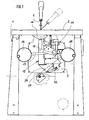
- the circular saw underlying the drawing has a cabinet-like machine frame 1, on which a table top 2 is added.
- the cabinet-like machine frame 1 is as shown Fig. 1 it can be seen on the operating side is provided with a Revisionsluke 3, by means of a in Fig. 1 removed inspection cover is closed. In Fig. 6 the inspection cover 4 is attached.
- the table top 2 has a passage slot, not shown in the drawings, through which the machining tool, here in the form of a saw blade 5, passes.
- the saw blade 5 is one of the best FIG. 2 recognizable splitting wedge 6 assigned to which a suction hood 7 may be attached.
- the saw blade 5 is adjustable in height to cut different thickness workpieces can.
- the saw blade 5 can be pivoted.
- the pivot axis is practically formed by the line of intersection of the surface of the table top 2 with the median plane of the saw blade 5.
- Two parking spaces are in Fig. 1 indicated by broken lines.
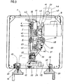
- the saw blade 5 is, as from the Fig. 2 and 3 can be removed, on a below the table top 2 located tool shaft 8 clamped by means of a associated electric motor 9 is driven.
- the motor shaft is offset from the tool shaft 8 and hereby, as best of Fig. 2 can be seen, drivingly connected by a countershaft 10, which may be a belt drive.
- the tool shaft 8 is like the Fig. 2 and 3 further show, mounted on a tool console 11 to which the motor 9 is mounted.
- the tool console 11 is in turn adjustable in height on a arranged below the table top 2, to the above-defined, pivotable to the top of the table coplanar pivot axis pivoting frame 12 was added.
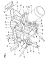
- Fig. 4 This one is how best Fig. 4 can be seen, attached to its opposite in the cutting direction opposite ends, concentric with the above-mentioned pivot axis extending, ring-shaped bearing strips 13 and pivotally mounted with this in screwed on the underside of the table top 2 bearing blocks 14.
- the bearing blocks 14 are provided with the bearing strips 13 associated Segmentnuten 15, in which engage the bearing strips 13 in the manner of tongue and groove.
- the table top 2, the bearing blocks 14 which can be screwed thereto and the swing frame 12, which can be accommodated thereon, and the tool console 11 which can be accommodated thereon form a jointly preassembled subassembly.
- the tool console 11 and the swing frame 12 are suitably formed as Gußformlinge, as from Fig. 4 clearly shows.
- the adjusting rod 17 may be formed, for example, as a threaded rod, etc.
- the threaded rod 17 is advantageously formed as a threaded spindle, on the one hand engages in a pivotally and axially fixed to the pivot frame 12 mounted nut 18 and on the other hand about the axis of rotation of the associated handwheel 16 is pivotally and via an angle gear 19 with the handwheel 16 together looks like out Fig. 3 is apparent.
- the angle gear 19 is formed by two bevel gears, one of which is connected to a hand wheel 16 connected to the frame side Stub shaft 20 and one on the adjacent, in a pivotable about the axis of the stub shaft 20 bearing housing 21 engaging end of the control rod 17 is received.
- the formation of the control rod 17 as a threaded spindle leads to a self-locking arrangement with large reduction.
- the threaded spindle associated nut 18 is, as best of Fig. 4 can be seen as formed about its axis pivotally mounted in a fork-shaped bearing lug 22 of the pivot frame 12 bolts, which is provided with a transverse to its axis threaded bore into which the vertical rod 17 forming threaded spindle engages.
- the height-adjustable recorded on the swing frame 12 tool console 11 is, as from the Fig. 2 to 4 emerges, guided on vertical guide rods 23 of the swing frame 12.
- two guide windows 23 flanking a pass-through window 24 for the tool shaft 8 or the bearing device associated therewith are provided.
- the tool console 11 is provided with the guide rods 23 associated bearing bushings 25.
- a parallel to the guide rods 23, standing on the swing frame recorded, as this associated actuator serving threaded spindle 26 is provided which is in engagement with a nut 27 attached to the tool console 11.
- the threaded spindle 26 is received on a tool bracket 11 engages under projection 28 of the swing frame 12 and driven by a arranged on the underside of the projection 28 bevel gear 29.
- the nut 27 is located on a projection 28 overarching projection 30 of the tool console eleventh
- the bevel gear 29 is formed by two bevel gears, one of which is attached to the projection 28 by a cross-pickup stub of the threaded spindle 26 and the second is mounted on an associated, mounted on a by a bracket 28 attached to the bracket gear housing mounted gear shaft 31.
- a rotary member 34 is drivingly connected to an associated mating gear 35 which is received on a rotatably mounted in the operating side wall of the machine frame 1 stub shaft 36 which carries an associated handwheel 37 at its outer end.
- the circulating organ 34 is expediently designed as a chain.
- the drive wheel 33 and the mating gear 35 are therefore formed as sprockets.
- the hand wheel 37 could also be attached to a drive wheel 33 receiving shaft.
- the illustrated embodiment facilitates a height-equal arrangement of the hand wheels 16 and 37th
- the threaded spindle 26 is driven via the described drive train in the form of the chain drive containing the rotary member 34, the articulated shaft 32 provided on both sides and the angle gear 29.
- the rotational movement of the threaded spindle 26 is converted by the nut 27 into an adjusting movement of the tool console 11. This results in a high overall reduction and self-locking.
- the length of the articulated shaft 32 provided with joints on both sides can be changed, so that the articulated shaft 32 permits a pivoting movement of the pivoting frame 12.
- the propeller shaft 32 is formed as a two-part shaft with two shaft sections 32a, b, which have telescopically engaging polygonal areas. These can be formed on the respective associated shaft portion.
- two handwheels 16 and 37 are provided, of which the handwheel 16 serves to effectuate a pivotal movement of the swing frame 12 and the handwheel 37 to effect a height adjustment of the tool bracket 11 received on the swing frame 12.
- the hand wheels 16 and 37 are arranged at a lateral distance at approximately the same height in the region of the operating side of the machine frame 1, as seen from Fig. 1 evident. But it would also be possible to accomplish the pivoting movement and height adjustment to provide only a common handwheel. This could be arranged axially adjustable and can be coupled in its end positions alternatively with a cooperating with the control rod 17 and the propeller shaft 32 organ.
- the swing frame 12 is expedient, as already mentioned above, formed as a molding. This one has, as from the Fig. 3 and 4 it can be seen, one of the tool shaft 8 associated penetration window 24 containing standing wall 38, which is provided on the tool-distal side with a peripheral edge-surrounding edge ribbing 39. This is designed so that two the passage window 24 flanking, over the entire height of the swing frame 12 continuous chambers 40 result, in each of which a guide rod 23 is arranged.
- the guide rods 23 are fastened with their upper and lower ends to the respective associated chamber closing edge flange.
- the tool console 11 is provided with protruding into the chambers 40, each one of a guide rod 23 interspersed guide bushing 25 containing projections 41.
- the threaded spindle 26 associated projection 28 of the swing frame 12 which may be integrated into the ribbing 39.
- the for receiving the adjusting rod 17 associated with the nut 18 provided, fork-shaped projection 22 is mounted in the region of the operating side facing the end of the swing frame 12 to this, suitably formed. In this case, the projection 22 may be integrated into the ribbing 39.
- machining tool 5 side facing the wall 38 of the swing frame 12 is not ribbed.
- only one at least laterally and laterally encircling, at the top omitted, or at least in the region of the machining tool interrupted edge flange 42 is provided on which a wall-parallel cover plate 43 is attached, such as Fig. 3 shows.
- a wall-parallel cover plate 43 is attached, such as Fig. 3 shows.
- the connecting piece 45 can by a hose not shown with a near a wall the machine frame 1 provided through-piece 46 may be connected, which may have a connection piece 47 for a outgoing from the suction hood 7 line and may be connected by a hose in a conventional manner with a suction fan.
- the chamber 44 is how out Fig. 3 can be seen, penetrated by a projecting from the wall 38 pin 48 on which the riving knife 6 is receivable.
- the tool console 11 is also formed as a molding, as shown in the Fig. 3 and 4 shows a parallel to the wall 38 of the swing frame 12, standing wall 49, to which on the one hand a tool shaft 8 associated bearing means 50 and the bearing bushes 25 containing projections 41 and on the other hand, the nut 27 bearing projection 30 are formed.
- the wall 49 is suitably ribbed.
- a wall-parallel plate 51 adjustably mounted, which carries the motor 9.
- the adjustability of the holding plate 51 allows a reliable tension of the belt of the belt drive 10.
- the holding plate 51 is held by screws which pass through associated slots.
- a counter-rotating to the actual machining tool 5 scoring tool is usually required.
- a Vorritzaggregat 53 containing a scoring tool 52 is shown, which can be selectively attached to the swing frame 12.
- the Vorritzaggregat 53 attached to the swing frame 12.
- the scoring unit is removed.
- the scoring tool 52 is in a plane with the machining tool 5 and cuts through the coating of a plate, which can then be severed by means of the machining tool 5 without the risk of breaking out of the coating.
- the scoring unit 53 includes an electric motor 54, which is connected via a suitably designed as a belt drive countershaft 55 drivingly with the scoring tool 52 receiving shaft 56.
- the Vorritzaggregat 53 is, as already mentioned, designed as a cultivation unit.
- the scoring unit 53 includes an attachment which can be received on an associated receiving device of the swing frame 12.
- the standing wall 38 of the swing frame 12, as seen from Fig. 4 can be removed, provided with the receiving device for the Vorritzaggregat 53 forming, projecting from the tool-distal side Anschraubdomen 57.
- the scoring unit includes a mounting plate 58, which, as indicated by arcuate slots 59, adjustable to the Anschraubdomen 57 can be fixed.
- a support block 60 is mounted on which a pre-scriber 52 containing adjusting block 61 is received in height and axially adjustable.
- the scoring tool 52 supporting shaft 56 is mounted, which is feasible with sufficient clearance for an axial and vertical adjustment by an associated recess of the wall 38.
- the said recess is in Fig. 4 covered by a cover plate 62.
- the control block 61 is as shown Fig. 5 further shows, provided with two screws 63, one of which is used for height adjustment and axial adjustment. The height adjustment takes place via the thread of the associated screw 63.
- the arrangement of the motor 54 is such that the belt of the countershaft 55 is tensioned in every position of the control block 61.
- the associated screw 63 with an in FIG. 5 not visible screw provided. This cooperates with a peripherally fitted in an associated recess of the control block, axially displaceable gear 75, which has a lateral collar, which is provided with a thread which engages in a mating thread of the control block.
- gear 75 together with the collar shaft 56 is mounted.
- the screws 63 are over in Fig. 2 and 4 shown holes 64 in the table top 2 and in the top of the swing frame 12 accessible from above and actuated by means of a suitable plug-in tool.
- the display devices each consist of a scale and an associated pointer, wherein the arrangement is such that a readability in the area of the operating side is given as out Fig. 6 evident.
- the angle indicator includes a mounted on a on the operating side of the machine frame 1 facing the end of the swing frame 12 parallel to the service-side wall of the machine frame 1, in Fig. 4
- the operating side wall of the machine frame 1, here the one of this wall forming the inspection cover 4 is, as shown Fig. 6 shows, provided with a window 67 in which the angle scale 66 appears.
- a pointer 68 is fixed, which indicates the set angular position.
- To improve the readability of the window 67 may be associated with a magnifying lens.
- the height indicator comprises at least one mounted in the region of the edge of a window 69 of the inspection cover 4 height scale 70, which is associated with a appearing in the region of the window 69 movable pointer 71.
- Fig. 4 shows attached to a parallel to the operating side wall of the machine frame 1 tab 72 which is fixed by means of a bracket 73 on the height-adjustable tool console 11.
- a number of different height scales 70 are expediently provided, which are assigned to different tool diameters. In the example shown are as out Fig. 6 it can be seen, two different height scales 70 are provided.
Landscapes
- Life Sciences & Earth Sciences (AREA)
- Engineering & Computer Science (AREA)
- Mechanical Engineering (AREA)
- Wood Science & Technology (AREA)
- Forests & Forestry (AREA)
- Sawing (AREA)
- Milling, Drilling, And Turning Of Wood (AREA)
- Fish Paste Products (AREA)
- Chemical And Physical Treatments For Wood And The Like (AREA)
- Bakery Products And Manufacturing Methods Therefor (AREA)
- Workshop Equipment, Work Benches, Supports, Or Storage Means (AREA)
- Soil Working Implements (AREA)
- Formation And Processing Of Food Products (AREA)
- Table Devices Or Equipment (AREA)
Description
- Die Erfindung betrifft eine Holzbearbeitungsmaschine, insbesondere eine Kreissäge, mit einem Maschinengestell, auf dem eine Tischplatte aufgenommen ist, und mit einem unterhalb der Tischplatte angeordneten, um eine mit der Oberseite der Tischplatte koplanare Schwenkachse schwenkbaren Schwenkrahmen, auf dem eine höhenverstellbare Werkzeugkonsole aufgenommen ist, die wenigstens ein einen zugeordneten Schlitz der Tischplatte durchgreifendes Bearbeitungswerkzeug trägt, das auf eine Welle aufspannbar ist, die mittels eines an der Werkzeugkonsole angebrachten Motors antreibbar ist.
- Eine Anordnung dieser Art ist beispielsweise aus der
EP 0 235 683 B1 bekannt. Bei dieser bekannten Anordnung ist der Schwenkrahmen im Bereich seines vorderen und hinteren Endes mit Gleitsteinen versehen, die paarweise in einen jeweils zugeordneten Bogenschlitz eines vorderen und hinteren, in das Maschinengestell integrierten, stationären Lagerschilds eingreifen. Die Lagerschilde sind an ihrem unteren, zum Bogenschlitz konzentrischen Rand mit einer Verzahnung versehen, mit der ein mittels eines Handrads antreibbares Ritzel im Eingriff ist. Die den Ritzeln zugeordnete Ritzelwelle, auf der das Handrad aufgenommen ist, ist auf dem Schwenkrahmen gelagert und aus dem Maschinengestell herausgeführt, das hierfür einen zum Bogenschlitz der stationären Lagerschilde konzentrischen Durchgriffsschlitz benötigt. - Nachteilig hierbei ist, dass die Ritzelwelle jede Schwenkbewegung des Schwenkrahmens mitmacht, so dass das auf der Ritzelwelle aufgenommene Handrad bei jeder Schwenkbewegung des Schwenkrahmens seine Position ändert. Dies ist aus bedienungstechnischen Gründen unerwünscht. Hinzu kommt, dass der von der Ritzelwelle durchgriffene Durchgriffsschlitz des Maschinengestells ein Sicherheitsrisiko darstellen kann und dementsprechend abgedeckt werden muss. Die direkte Übertragung der Drehbewegung des Handrads auf den Schwenkrahmen ist auch hinsichtlich der erzielbaren Genauigkeit ungünstig. Außerdem ist bei der bekannten Anordnung der im Maschinengestell aufgehängte Schwenkrahmen von der Tischplatte getrennt, was die Montage erschwert.
- Hiervon ausgehend ist es daher die Aufgabe der vorliegenden Erfindung, eine Anordnung eingangs erwähnter Art mit einfachen und kostengünstigen Mitteln so zu verbessern, dass nicht nur eine hohe Bedienungsfreundlichkeit, Sicherheit und Genauigkeit erreicht wird, sondern auch ein sinnfälliger Aufbau.
- Diese Aufgabe wird erfindungsgemäß dadurch gelöst, dass der Schwenkrahmen im Bereich seiner in Schnittrichtung einander entgegen gesetzten Enden auf an der Unterseite der Tischplatte anbringbaren Lagerböcken schwenkbar aufgehängt und mittels einer angelenkten, mit Schwenkfreiheitsgrad angeordneten Stellstange verschwenkbar ist, dass die auf dem Schwenkrahmen aufgenommene Werkzeugkonsole mittels eines auf dem Schwenkrahmen angeordneten Stellorgans in der Höhe verstellbar ist, das mit einer verlängerbaren Gelenkwelle antriebsmäßig verbunden ist, und dass die Stellstange und die Gelenkwelle mittels wenigstens eines an der Bedienungsseite des Maschinengestells fest positionierten Bedienungsorgans betätigbar sind.
- Die Tischplatte sowie der Schwenkrahmen samt Werkzeugkonsole bilden hier in vorteilhafter Weise eine gemeinsam vormontierbare Baugruppe. Dies erleichtert die Erzielung einer exakten Lage der mit der Tischoberfläche koplanaren Schwenkachse des Schwenkrahmens und damit eine hohe Arbeitsgenauigkeit. Die dem Schwenkrahmen zugeordnete, mittels eines Bedienungsorgans betätigbare Stellstange ermöglicht zudem eine hohe Untersetzung, was sich vorteilhaft auf die erzielbare Bediengenauigkeit auswirkt. Dasselbe gilt für die der Werkzeugkonsole zugeordnete Gelenkwelle, der Untersetzungseinrichtungen vor- und/oder nachgeordnet sein können. Ein weiterer Vorteil der erfindungsgemäßen Maßnahmen ist darin zu sehen, dass jedes Bedienungsorgan in Folge der Beweglichkeit innerhalb des Antriebszugs zum Schwenkrahmen bzw. zur Werkzeugkonsole in seiner Position stationär ist, so dass auch kein einer mit einem Betätigungsorgan verbundenen Welle zugeordneter Durchgriffsschlitz des Gehäuses benötigt wird. Die Folge davon sind eine hohe Bedienungsfreundlichkeit und Sicherheit sowie eine hohe Stabilität des Maschinengehäuses. Mit den erfindungsgemäßen Maßnahmen werden daher die Nachteile des eingangs genannten Standes der Technik in vorteilhafter Weise vollständig vermieden.
- Vorteilhafte Ausgestaltungen und zweckmäßige Fortbildungen der übergeordneten Maßnahmen sind in den Unteransprüchen angegeben.
- So kann die dem Schwenkrahmen zugeordnete Stellstange vorteilhaft als Gewindespindel ausgebildet sein, die einerseits in eine schwenkbar und in axialer Richtung feststehend im Schwenkrahmen aufgenommene Mutter eingreift und andererseits um die Achse des zugeordneten Betätigungsorgans schwenkbar gelagert ist und über ein Winkelgetriebe mit dem zugeordneten Betätigungsorgan zusammenwirkt. Die Verwendung einer Gewindespindel ermöglicht eine vergleichsweise hohe Untersetzung, was bei Bedarf durch entsprechende Gestaltung des Winkelgetriebes noch unterstützt werden kann. Zudem ergibt die Gewindespindel in vorteilhafter Weise eine Selbsthemmung, was den Bedienungskomfort und die Genauigkeit unterstützt.
- In weiterer Fortbildung der übergeordneten Maßnahmen kann das der Werkzeugkonsole zugeordnete Stellorgan vorteilhaft als stehend auf dem Schwenkrahmen angeordnete Gewindespindel ausgebildet sein, die in eine an der Werkzeugkonsole fest angebrachte Mutter eingreift und über ein Winkelgetriebe mit der an beiden Enden mit Gelenken versehenen Gelenkwelle verbunden ist. Auch hierbei lassen sich in vorteilhafter Weise eine hohe Untersetzung sowie eine Selbsthemmung erreichen.
- Eine weitere, besonders zu bevorzugende Maßnahme kann darin bestehen, dass der Stellstange und der Stellspindel jeweils ein eigenes Betätigungsorgan zugeordnet ist, wobei diese Betätigungsorgane vorteilhaft mit seitlichem Abstand auf gleicher Höhe angeordnet sein können. Diese Maßnahmen ermöglichen eine synchrone Betätigung der Schwenkeinrichtung und der Höhenverstellung.
- Zweckmäßig kann der Schwenkrahmen als Gußformling ausgebildet sein, der eine stehende Wand enthält, die mit wenigstens einem nach oben offenen, von einer ein Bearbeitungswerkzeug tragenden Welle durchgriffenen Durchgriffsfenster versehen ist und auf der werkzeugfernen Seite einen die der Werkzeugkonsole zugeordnete, stehende Gewindespindel aufnehmenden Vorsprung sowie eine spindelparallele Führung für die Werkzeugkonsole aufweist. Hierdurch ergibt sich eine kostengünstig herstellbare, verwindungssteife Ausbildung des Schwenkrahmens. Es genügt daher in vorteilhafter Weise eine Stellstange.
- Vorteilhaft kann der Schwenkrahmen zumindest werkzeugseitig mit einem umlaufenden, vorzugsweise im Werkzeugbereich unterbrochenen Randflansch versehen sein, an dem eine Abdeckplatte angebracht ist. Hierdurch wird in vorteilhafter Weise eine dem Werkzeug zugeordnete, nach oben offene Kammer gebildet, die an eine Absaugeinrichtung anschließbar ist, was die Spanabfuhr erleichtert.
- Zweckmäßig kann auch die Werkzeugkonsole als Gußformling ausgebildet sein, der eine stehende Wand enthält, die einerseits mit mit Führungsbüchsen versehenen Vorsprüngen sowie mit einem der das Werkzeug tragenden Welle zugeordneten Lagerbereich und andererseits mit einem die mit der das Stellorgan bildenden Gewindespindel zusammenwirkende Mutter enthaltenden Vorsprung versehen ist. Hierbei ergibt sich eine kostengünstig herstellbare, verwindungssteife Ausbildung der Werkzeugkonsole. Gleichzeitig führt die Verwendung von Gußformlingen für den Schwenkrahmen und die Werkzeugkonsole auch zu einer hohen Schwingungsfreiheit, was sich ebenfalls positiv auf die erzielbare Genauigkeit auswirkt.
- Weitere vorteilhafte Ausgestaltungen und zweckmäßige Fortbildungen der übergeordneten Maßnahmen sind in den restlichen Unteransprüchen angegeben und aus der nachstehenden Beispielsbeschreibung anhand der Zeichnung näher entnehmbar.
- In der nachstehend beschriebenen Zeichnung zeigen:
- Figur 1
- eine Ansicht der Bedienungsseite einer erfindungsgemäßen Kreissäge mit abgenommenen Revisionsdeckel und teilweise ausgebrochener Frontwand,
- Figur 2
- einen Längsschnitt durch die Anordnung gemäß
Figur 1 , - Figur 3
- eine schematische Draufsicht auf die Anordnung gemäß
Figur 1 bei entfernter Tischplatte, - Figur 4
- eine perspektivische Ansicht des Schwenkrahmens mit aufgenommener Werkzeugkonsole und zugeordneten Lagerböcken,
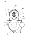
- Figur 5
- eine Ansicht eines an den Schwenkrahmen anbaubaren Vorritzaggregats und
- Figur 6
- eine der
Figur 1 entsprechende Ansicht der erfindungsgemäßen Kreissäge mit angebrachtem, Anzeigeeinrichtungen enthaltendem Revisionsdeckel. - Hauptanwendungsgebiet der Erfindung sind mit einem Bearbeitungswerkzeug in Form eines kreisförmigen Sägenblatts ausgestattete Kreissägen. Die der Zeichnung zugrunde liegende Kreissäge besitzt ein gehäuseartiges Maschinengestell 1, auf dem eine Tischplatte 2 aufgenommen ist. Das gehäuseartige Maschinengestell 1 ist, wie aus
Fig. 1 ersichtlich ist, an der Bedienseite mit einer Revisionsluke 3 versehen ist, die mittels eines inFig. 1 entfernten Revisionsdeckels verschließbar ist. InFig. 6 ist der Revisionsdeckel 4 angebracht. Die Tischplatte 2 besitzt einen in den Zeichnungen nicht näher dargestellten Durchtrittsschlitz, durch den das Bearbeitungswerkzeug, hier in Form eines Sägenblatts 5 durchgreift. Im Sägenblatt 5 ist ein am besten ausFigur 2 erkennbarer Spaltkeil 6 zugeordnet, an dem eine Absaughaube 7 angebracht sein kann. - Das Sägenblatt 5 ist in der Höhe verstellbar, um unterschiedlich dicke Werkstücke schneiden zu können. Um gegenüber der Oberfläche der Tischplatte 2 geneigte Schnitte ausführen zu können, kann das Sägenblatt 5 verschwenkt werden. Die Schwenkachse wird praktisch durch die Verschneidungslinie der Oberfläche der Tischplatte 2 mit der Mittelebene des Sägenblatts 5 gebildet. Dabei kann ausgehend von der in
Fig. 1 mit durchgehenden Linien angedeuteten lotrechten Mittelstellung eine Schwenkbarkeit nach jeweils einer Seite (links oder rechts) oder nach beiden Seiten vorgesehen sein. Zwei Stellmöglichkeiten sind inFig. 1 mit unterbrochenen Linien angedeutet. - Das Sägenblatt 5 ist, wie aus den
Fig. 2 und3 entnehmbar ist, auf eine unterhalb der Tischplatte 2 sich befindende Werkzeugwelle 8 aufspannbar, die mittels eines zugeordneten Elektromotors 9 antreibbar ist. Zweckmäßig ist dabei die Motorwelle gegenüber der Werkzeugwelle 8 versetzt und hiermit, wie am besten ausFig. 2 erkennbar ist, durch ein Vorgelege 10 antriebsmäßig verbunden, bei dem es sich um einen Riementrieb handeln kann. Die Werkzeugwelle 8 ist, wie dieFig. 2 und3 weiter zeigen, auf einer Werkzeugkonsole 11 gelagert, an der auch der Motor 9 angebracht ist. Die Werkzeugkonsole 11 ist ihrerseits in der Höhe verstellbar auf einem unterhalb der Tischplatte 2 angeordneten, um die oben definierte, zur Tischoberseite koplanare Schwenkachse schwenkbaren Schwenkrahmen 12 aufgenommen. - Dieser ist, wie am besten aus
Fig. 4 ersichtlich ist, mit an seinen in Schnittrichtung einander entgegengesetzten Enden angebrachten, konzentrisch zur oben genannten Schwenkachse verlaufenden, ringsegmentförmigen Lagerleisten 13 versehen und mit diesen in an der Unterseite der Tischplatte 2 anschraubbaren Lagerböcken 14 schwenkbar gelagert. Die Lagerböcke 14 sind mit den Lagerleisten 13 zugeordneten Segmentnuten 15 versehen, in welche die Lagerleisten 13 nach Art von Nut und Feder eingreifen. Die Tischplatte 2, die hieran anschraubbaren Lagerböcke 14 sowie der hierauf aufnehmbare Schwenkrahmen 12 und die auf diesem aufnehmbare Werkzeugkonsole 11 bilden eine gemeinsam vormontierbare Baugruppe. Die Werkzeugkonsole 11 und der Schwenkrahmen 12 sind zweckmäßig als Gußformlinge ausgebildet, wie ausFig. 4 anschaulich hervorgeht. - Zum Schwenken des Schwenkrahmens 12 ist diesem, wie aus den
Fig. 1 und3 entnehmbar ist, eine mittels eines im Bereich der Bedienungsseite des Maschinengestells 1 angeordneten Handrads 16 betätigbare Stellstange 17 zugeordnet, die an den Schwenkrahmen 12 angelenkt ist und den erforderlichen Schwenkfreiheitsgrad besitzt. Die Stellstange 17 kann z.B. als Gewindestange etc. ausgebildet sein. Im dargestellten Beispiel ist die Gewindestange 17 vorteilhaft als Gewindespindel ausgebildet, die einerseits in eine schwenkbar und in axialer Richtung feststehend am Schwenkrahmen 12 angebrachte Mutter 18 eingreift und andererseits um die Drehachse des zugeordneten Handrads 16 schwenkbar ist und die über ein Winkelgetriebe 19 mit dem Handrad 16 zusammen wirkt, wie ausFig. 3 ersichtlich ist. Das Winkelgetriebe 19 wird durch zwei Kegelräder gebildet, von denen eines auf einem mit dem Handrad 16 verbundenen, gestellseitig gelagerten Wellenstummel 20 und eines auf dem benachbarten, in ein um die Achse des Wellenstummels 20 schwenkbares Lagergehäuse 21 eingreifenden Ende der Stellstange 17 aufgenommen ist. Die Ausbildung der Stellstange 17 als Gewindespindel führt zu einer selbsthemmenden Anordnung mit großer Untersetzung. Die der Gewindespindel zugeordnete Mutter 18 ist, wie am besten ausFig. 4 erkennbar ist, als um seine Achse schwenkbar in einem gabelförmigen Lageransatz 22 des Schwenkrahmens 12 gelagerter Bolzen ausgebildet, der mit einer quer zu seiner Achse verlaufenden Gewindebohrung versehen ist, in welche die die Steilstange 17 bildende Gewindespindel eingreift. - Die in der Höhe verstellbar auf dem Schwenkrahmen 12 aufgenommene Werkzeugkonsole 11 ist, wie aus den
Fig. 2 bis 4 hervorgeht, auf vertikalen Führungsstangen 23 des Schwenkrahmens 12 geführt. Im dargestellten Beispiel sind zwei ein Durchgriffsfenster 24 für die Werkzeugwelle 8 bzw. die dieser zugeordnete Lagereinrichtung flankierende Führungsstangen 23 vorgesehen. Die Werkzeugkonsole 11 ist mit den Führungsstangen 23 zugeordneten Lagerbüchsen 25 versehen. Zur Bewerkstelligung einer vertikalen Verstellbarkeit der Werkzeugkonsole 11 auf dem Schwenkrahmen 12 ist, wie dieFig. 2 bis 4 weiter erkennen lassen, eine zu den Führungsstangen 23 parallele, stehend auf dem Schwenkrahmen aufgenommene, als diesem zugeordnetes Stellorgan dienende Gewindespindel 26 vorgesehen, die im Eingriff mit einer an der Werkzeugkonsole 11 befestigten Mutter 27 ist. - Die Gewindespindel 26 ist auf einer die Werkzeugkonsole 11 untergreifenden Auskragung 28 des Schwenkrahmens 12 aufgenommen und über ein an der Unterseite der Auskragung 28 angeordnetes Winkelgetriebe 29 antreibbar. Die Mutter 27 befindet sich auf einer die Auskragung 28 übergreifenden Auskragung 30 der Werkzeugkonsole 11.
- Das Winkelgetriebe 29 wird durch zwei Kegelräder gebildet, von denen eines an einem die Auskragung 28 durchgreifenden Aufnahmestummel der Gewindespindel 26 befestigt ist und das zweite auf einer zugeordneten, auf einem durch einen an der Auskragung 28 befestigten Bügel gebildeten Getriebegehäuse gelagerten Getriebewelle 31 aufgenommen ist. An die Getriebewelle 31 ist eine Gelenkwelle 32 angelenkt, die mit ihrem anderen Ende, wie am besten aus
Fig. 2 ersichtlich ist, an ein an der Innenseite der bedienungsseitigen Wand des Maschinengestells 1 drehbar gelagertes Antriebsrad 33 angelenkt ist. Dieses ist, wie aus denFig. 2 und3 ersichtlich ist, über ein Umlauforgan 34 antriebsmäßig mit einem zugeordneten Gegenrad 35 verbunden, das auf einem in der bedienungsseitigen Wand des Maschinengestells 1 drehbar gelagerten Wellenstummel 36 aufgenommen ist, das an seinem äußeren Ende ein zugeordnetes Handrad 37 trägt. Das Umlauforgan 34 ist zweckmäßig als Kette ausgebildet. Das Antriebsrad 33 und das Gegenrad 35 sind daher als Kettenräder ausgebildet. Natürlich könnte das Handrad 37 auch an einer das Antriebsrad 33 aufnehmenden Welle angebracht sein. Die dargestellte Ausführung erleichtert jedoch eine höhengleiche Anordnung der Handräder 16 und 37. - Durch Drehen des Handrads 37 wird die Gewindespindel 26 über den beschriebenen Antriebszug in Form des das Umlauforgan 34 enthaltenden Kettentriebs, der beidseitig mit Gelenken versehenen Gelenkwelle 32 und des Winkelgetriebes 29 angetrieben. Die Drehbewegung der Gewindespindel 26 wird durch die Mutter 27 in eine Stellbewegung der Werkzeugkonsole 11 umgesetzt. Dabei ergeben sich eine hohe Gesamtuntersetzung sowie eine Selbsthemmung.
- Die Länge der beidseitig mit Gelenken versehenen Gelenkwelle 32 ist veränderbar, so dass die Gelenkwelle 32 eine Schwenkbewegung des Schwenkrahmens 12 zulässt. Hierzu ist die Gelenkwelle 32 als zweiteilige Welle mit zwei Wellenabschnitten 32a, b ausgebildet, die teleskopartig ineinander eingreifende Mehrkantbereiche aufweisen. Diese können an den jeweils zugeordneten Wellenabschnitt angeformt sein.
- Im dargestellten Beispiel sind zwei Handräder 16 bzw. 37 vorgesehen, von denen das Handrad 16 zur Bewerkstelligung einer Schwenkbewegung des Schwenkrahmens 12 und das Handrad 37 zur Bewerkstelligung einer Höhenverstellung der auf dem Schwenkrahmen 12 aufgenommenen Werkzeugkonsole 11 dient. Die Handräder 16 bzw. 37 sind mit seitlichem Abstand auf etwa gleicher Höhe im Bereich der Bedienungsseite des Maschinengestells 1 angeordnet, wie aus
Fig. 1 hervorgeht. Es wäre aber auch denkbar, zur Bewerkstelligung der Schwenkbewegung und Höhenverstellung nur ein gemeinsames Handrad vorzusehen. Dieses könnte axial verstellbar angeordnet und in seinen Endstellungen alternativ mit einem mit der Stellstange 17 bzw. der Gelenkwelle 32 zusammenwirkenden Organ kuppelbar sein. - Der Schwenkrahmen 12 ist zweckmäßig, wie oben bereits erwähnt wurde, als Gußformling ausgebildet. Dieser besitzt, wie aus den
Fig. 3 und4 erkennbar ist, eine das der Werkzeugwelle 8 zugeordnete Durchgriffsfenster 24 enthaltende stehende Wand 38, die auf der werkzeugfernen Seite mit einer einen randseitig umlaufenden Randflansch enthaltenden Verrippung 39 versehen ist. Diese ist so ausgebildet, dass sich zwei das Durchtrittsfenster 24 flankierende, über die ganze Höhe des Schwenkrahmens 12 durchgehende Kammern 40 ergeben, in denen jeweils eine Führungsstange 23 angeordnet ist. Die Führungsstangen 23 sind mit ihren oberen und unteren Enden an den die jeweils zugeordnete Kammer verschließenden Randflanschbereichen befestigt. Die Werkzeugkonsole 11 ist mit in die Kammern 40 hineinragenden, jeweils eine von einer Führungsstange 23 durchsetzte Führungsbüchse 25 enthaltenden Vorsprüngen 41 versehen. Im Bereich unterhalb des Durchgriffsfensters 24 befindet sich die der Gewindespindel 26 zugeordnete Auskragung 28 des Schwenkrahmens 12, die in die Verrippung 39 integriert sein kann. Der zur Aufnahme der der Stellstange 17 zugeordneten Mutter 18 vorgesehene, gabelförmige Ansatz 22 ist im Bereich des der Bedienungsseite zugewandten Endes des Schwenkrahmens 12 an diesem angebracht, zweckmäßig angeformt. Hierbei kann der Ansatz 22 in die Verrippung 39 integriert sein. - Auf der dem Bearbeitungswerkzeug 5 zugewandten Seite ist die Wand 38 des Schwenkrahmens 12 nicht verrippt. Hier ist lediglich ein zumindest seitlich und unten umlaufender, oben weggelassener, bzw. zumindest im Bereich des Bearbeitungswerkzeugs unterbrochener Randflansch 42 vorgesehen, an dem eine wandparallele Abdeckplatte 43 angebracht ist, wie
Fig. 3 zeigt. Auf diese Weise ergibt sich eine nach oben offene Aufnahmekammer 44 für das Bearbeitungswerkzeug 5. Von der Aufnahmekammer 44 geht ein in denFig. 2 und3 gezeigter Anschlussstutzen 45 für eine Absaugleitung ab. Der Anschlussstutzen 45 kann durch einen nicht näher dargestellten Schlauch mit einem im Bereich einer Wand des Maschinengestells 1 vorgesehenen Durchführstutzen 46 verbunden sein, der einen Anschlussstutzen 47 für eine von der Absaughaube 7 abgehende Leitung aufweisen kann und durch einen Schlauch in an sich bekannter Weise mit einem Absauggebläse verbunden sein kann. Die Kammer 44 wird, wie ausFig. 3 ersichtlich ist, von einem von der Wand 38 abstehenden Stift 48 durchgriffen, auf dem der Spaltkeil 6 aufnehmbar ist. - Die Werkzeugkonsole 11 ist ebenfalls als Gußformling ausgebildet, der wie aus den
Fig. 3 und4 hervorgeht, eine zur Wand 38 des Schwenkrahmens 12 parallele, stehende Wand 49 enthält, an die einerseits eine der Werkzeugwelle 8 zugeordnete Lagereinrichtung 50 und die die Lagerbüchsen 25 enthaltenden Vorsprünge 41 und andererseits die die Mutter 27 tragende Auskragung 30 angeformt sind. Auf der vom Schwenkrahmen 12 abgewandten Seite ist die Wand 49 zweckmäßig verrippt. An dieser Verrippung ist, wie aus denFig. 2 bis 4 hervorgeht, eine wandparallele Halteplatte 51 verstellbar angebracht, die den Motor 9 trägt. Die Verstellbarkeit der Halteplatte 51 ermöglicht eine zuverlässige Spannung des Riemens des Riementriebs 10. Im dargestellten Beispiel wird die Halteplatte 51 durch Schrauben gehalten, die zugeordnete Langlöcher durchgreifen. - Beim Schneiden von beschichteten Platten etc. wird in der Regel ein gegenläufig zum eigentlichen Bearbeitungswerkzeug 5 drehendes Vorritzwerkzeug benötigt. In
Fig. 5 ist ein ein Vorritzwerkzeug 52 enthaltendes Vorritzaggregat 53 dargestellt, das wahlweise an den Schwenkrahmen 12 angesetzt werden kann. In denFiguren 2 und3 ist das Vorritzaggregat 53 am Schwenkrahmen 12 angebracht. InFigur 4 ist das Vorritzaggregat entfernt. Das Vorritzwerkzeug 52 befindet sich in einer Ebene mit dem Bearbeitungswerkzeug 5 und durchtrennt die Beschichtung einer Platte, die anschließend mit Hilfe des Bearbeitungswerkzeugs 5 ohne die Gefahr des Ausbrechens der Beschichtung durchtrennt werden kann. Das Vorritzaggregat 53 enthält einen Elektromotor 54, der über ein zweckmäßig als Riementrieb ausgebildetes Vorgelege 55 antriebsmäßig mit einer das Vorritzwerkzeug 52 aufnehmenden Welle 56 verbunden ist. Das Vorritzaggregat 53 ist, wie schon erwähnt, als Anbauaggregat ausgebildet. Hierzu enthält das Vorritzaggregat 53 eine Anbaueinrichtung, die auf einer zugeordneten Aufnahmeeinrichtung des Schwenkrahmens 12 aufnehmbar ist. - Im dargestellten Beispiel ist die stehende Wand 38 des Schwenkrahmens 12, wie aus
Fig. 4 entnehmbar ist, mit die Aufnahmeeinrichtung für das Vorritzaggregat 53 bildenden, von der werkzeugfernen Seite abstehenden Anschraubdomen 57 versehen. Das Vorritzaggregat enthält ein Anbauschild 58, das, wie durch Bogenschlitze 59 angedeutet ist, verstellbar an den Anschraubdomen 57 festlegbar ist. - Am Anbauschild 58 ist, wie aus
Fig. 5 ersichtlich ist, einerseits der Motor 54 und andrerseits ein Stützblock 60 angebracht, auf dem ein das Vorritzwerkzeug 52 enthaltender Stellblock 61 in der Höhe und axial verstellbar aufgenommen ist. Im Stellblock 61 ist die das Vorritzwerkzeug 52 tragende Welle 56 gelagert, die mit ausreichend Spiel für eine axiale und vertikale Verstellung durch eine zugeordnete Ausnehmung der Wand 38 durchführbar ist. Die genannte Ausnehmung ist inFig. 4 durch eine Abdeckplatte 62 abgedeckt. Der Stellblock 61 ist, wie ausFig. 5 weiter hervorgeht, mit zwei Stellschrauben 63 versehen, von denen eine zur Höhenverstellung und eine zur axialen Verstellung dient. Die Höhenverstellung erfolgt über das Gewinde der zugeordneten Schraube 63. Die Anordnung des Motors 54 ist so, dass der Riemen des Vorgeleges 55 in jeder Stellung des Stellblocks 61 gespannt ist. Zur Axialverstellung ist die zugeordnete Schraube 63 mit einer inFigur 5 nicht sichtbaren Schnecke versehen. Diese wirkt mit einem umfangsseitig in eine zugeordnete Ausnehmung des Stellblocks eingepassten, axial verschiebbaren Zahnrad 75 zusammen, das einen seitlichen Bund aufweist, der mit einem Gewinde versehen ist, das in ein Gegengewinde des Stellblocks eingreift. Im Zahnrad 75 samt Bund ist die Welle 56 gelagert. Die Stellschrauben 63 sind über inFig. 2 und4 gezeigte Löcher 64 in der Tischplatte 2 und in der Oberseite des Schwenkrahmens 12 von oben erreichbar und mittels eines geeigneten Steckwerkzeugs betätigbar. - Zur Erleichterung einer genauen Einstellung der gewünschten Höhe des Bearbeitungswerkzeugs 5 bzw. des gewünschten Schwenkwinkels des Bearbeitungswerkzeugs 5 sind zugeordnete Anzeigeeinrichtungen vorgesehen, auf denen die eingestellte Höhe bzw. der eingestellte Schwenkwinkel ablesbar sind. Die Anzeigeeinrichtungen bestehen jeweils aus einer Skala und einem zugeordneten Zeiger, wobei die Anordnung so getroffen ist, dass eine Ablesbarkeit im Bereich der Bedienungsseite gegeben ist, wie aus
Fig. 6 hervorgeht. - Die Winkelanzeigeeinrichtung enthält eine auf einer am der Bedienungsseite des Maschinengestells 1 zugewandten Ende des Schwenkrahmens 12 befestigten parallel zur bedienungsseitigen Wand des Maschinengestells 1 sich erstreckenden, in
Fig. 4 gezeigten Platte 65 angebrachte Winkelskala 66. Die bedienungsseitige Wand des Maschinengestells 1, hier der ein Element dieser Wand bildende Revisionsdeckel 4 ist, wie ausFig. 6 hervorgeht, mit einem Fenster 67 versehen, in welchem die Winkelskala 66 erscheint. Am Rand des Fensters 66 ist ein Zeiger 68 fest angebracht, der die eingestellte Winkelstellung anzeigt. Zur Verbesserung der Ablesbarkeit kann dem Fenster 67 eine Vergrößerungslinse zugeordnet sein. - Die Höhenanzeigeeinrichtung enthält wenigstens eine im Bereich des Rands eines Fensters 69 des Revisionsdeckels 4 angebrachte Höhenskala 70, der ein im Bereich des Fensters 69 erscheinender beweglicher Zeiger 71 zugeordnet ist. Dieser ist, wie
Fig. 4 zeigt, an einer zur bedienungsseitigen Wand des Maschinengestells 1 parallelen Lasche 72 angebracht, die mittels eines Bügels 73 an der in der Höhe verstellbaren Werkzeugkonsole 11 befestigt ist. Im Bereich des Fensters 69 sind zweckmäßig mehrere unterschiedliche Höhenskalen 70 vorgesehen, die unterschiedlichen Werkzeugdurchmessern zugeordnet sind. Im dargestellten Beispiel sind, wie ausFig. 6 ersichtlich ist, zwei verschiedene Höhenskalen 70 vorgesehen.
Claims (10)
- Holzbearbeitungsmaschine, insbesondere Kreissäge, mit einem Maschinengestell (1), auf dem eine Tischplatte (2) aufgenommen ist, und mit einem unterhalb der Tischplatte (2) angeordneten, um eine mit der Oberseite der Tischplatte (2) koplanare Schwenkachse schwenkbaren Schwenkrahmen (12), auf dem eine höhenverstellbare Werkzeugkonsole (11) angeordnet ist, die wenigstens ein einen zugeordneten Schlitz der Tischplatte (2) durchgreifendes Bearbeitungswerkzeug (5) trägt, das auf eine Welle (8) aufspannbar ist, die mittels eines an der Werkzeugkonsole (11) angebrachten Motors (9) antreibbar ist, dadurch gekennzeichnet, dass der Schwenkrahmen (12) im Bereich seiner in Schnittrichtung einander entgegengesetzten Enden auf an der Unterseite der Tischplatte (2) anbringbaren Lagerböcken (14) schwenkbar aufgehängt und mittels einer angelenkten, mit Schwenkfreiheitsgrad angeordneten Stellstange (17) verschwenkbar ist, dass die auf dem Schwenkrahmen (12) aufgenommene Werkzeugkonsole (11) mittels eines auf dem Schwenkrahmen (12) angeordneten Stellorgans in der Höhe verstellbar ist, das mit einer verlängerbaren Gelenkwelle (32) antriebsmäßig verbunden ist, und dass die Stellstange (17) und die Gelenkwelle (32) mittels wenigstens eines an der Bedienungsseite des Maschinengestells (1) fest positionierten Bedienungsorgans (16) bzw. (37) betätigbar sind.
- Holzbearbeitungsmaschine nach Anspruch 1, dadurch gekennzeichnet, dass die dem Schwenkrahmen (12) zugeordnete Stellstange (17) als Gewindespindel ausgebildet ist, die einerseits in eine schwenkbar und in axialer Richtung feststehend im Schwenkrahmen (12) aufgenommene Mutter (18) eingreift und andererseits um die Achse des zugeordneten Betätigungsorgans (16) schwenkbar gelagert ist und über ein Winkelgetriebe (19) mit dem zugeordneten Betätigungsorgan (16) zusammenwirkt, wobei die Mutter (18) vorzugsweise als mit einer quer zu seiner Achse verlaufenden Gewindebohrung versehener Bolzen ausgebildet ist, der auf einem gabelförmigen Ansatz (22) des Schwenrahmens (12) um seine Achse schwenkbar gelagert ist.
- Holzbearbeitungsmaschine nach einem der vorhergehenden Ansprüche, dadurch gekennzeichnet, dass das der Werkzeugkonsole (11) zugeordnete Stellorgan (26) als stehend auf dem Schwenkrahmen (12) angeordnete Gewindespindel ausgebildet ist, die in eine an der Werkzeugkonsole (11) fest angebrachte Mutter (27) eingreift und über ein Winkelgetriebe (29) mit der an beiden Enden mit Gelenken versehenen Gelenkwelle (32) verbunden ist, die vorzugsweise an ein mit dem zugeordneten Betätigungsorgan (37) über ein Umlauforgan (34) antriebsmäßig verbundenes, an der Innenseite der bedienungsseitigen Wand des Maschinengestells (1) vorgesehenes Antriebsrad (33) angelenkt ist und zwei Wellenabschnitte (32a, b) aufweist, die mit angeformten Mehrkantbereichen teleskopartig ineinander eingreifen, und dass der Schwenkrahmen (12) mit stehend angeordneten Führungsstangen (23) versehen ist, auf denen die Werkzeugkonsole (11) mit zugeordneten Führungsbüchsen (25) verschiebbar gelagert ist.
- Holzbearbeitungsmaschine nach einem der vorhergehenden Ansprüche, dadurch gekennzeichnet, dass der Stellstange (17) und der Gelenkwelle (32) jeweils ein eigenes Betätigungsorgan (16 bzw. 37) zugeordnet ist und dass die Betätigungsorgane (16, 37) vorzugsweise mit seitlichem Abstand auf gleicher Höhe angeordnet sind.
- Holzbearbeitungsmaschine nach einem der vorhergehenden Ansprüche, dadurch gekennzeichnet, dass der Schwenkrahmen (12) als Gußformling ausgebildet ist, der eine stehende Wand (38) enthält, die mit wenigstens einem nach oben offenen, von einer ein Bearbeitungswerkzeug (5) tragenden Welle (8) durchgriffenen Durchtrittsfenster (24) versehen ist und die auf der werkzeugfernen Seite einen die das der Werkzeugkonsole (11) zugeordnete Steilorgan (26) bildende Gewindespindel aufnehmenden Vorsprung (28) sowie die der Werkzeugkonsole (11) zugeordneten Führungsstangen (23) aufweist, wobei vorzugsweise der Schwenkrahmen (12) werkzeugseitig mit einem zumindest seitlich und unten umlaufenden Randflansch (42) versehen ist, an dem eine Abdeckplatte (43) angebracht ist, die eine dem Bearbeitungswerkzeug (5) zugeordnete Kammer (44) begrenzt und wobei vorzugsweise der Schwenkrahmen (12) mit einem von der Kammer (44) abgehenden Anschlussstutzen (45) für eine Absaugleitung versehen ist, die vorzugsweise über einen Durchführstutzen (46) aus dem gehäuseartigen Maschinengestell herausführbar ist und wobei vorzugsweise die stehende Wand (38) des Schwenkrahmens (12) auf der werkzeugfernen Seite mit einer durch einen umlaufenden Randflansch begrenzten Verrippung (39) versehen ist, die zwei die Durchgriffsausnehmung (24) flankierende, über die Höhe der Wand (38) durchgehende Kammern (40) bildet, denen jeweils eine mit ihren Enden randflanschseitig befestigte Führungsstange (23) zur Führung der Werkzeugkonsole (11) zugeordnet ist.
- Holzbearbeitungsmaschine nach einem der vorhergehenden Ansprüche, dadurch gekennzeichnet, dass die den Schwenkrahmen (12) aufnehmenden Lagerböcke (14) mit einer Segmentnut (15) versehen sind, in die am Schwenkrahmen (12) angebrachte, segmentförmige Lagerleisten (13) nach Art von Nut und Feder eingreifen.
- Holzbearbeitungsmaschine nach einem der vorhergehenden Ansprüche, dadurch gekennzeichnet, dass die Werkzeugkonsole (11) als Gußformling ausgebildet ist, der eine stehende Wand (49) enthält, die einerseits mit die Führungsbüchsen (25) enthaltenden Vorsprüngen (41) sowie mit einer der das Bearbeitungswerkzeug (5) tragenden Welle (8) zugeordneten Lagereinrichtung (50) und andererseits mit einem die mit der zugeordneten Gewindespindel zusammenwirkende Mutter (27) enthaltenden Vorsprung (30) versehen ist, wobei vorzugsweise die Wand (49) der Werkzeugkonsole (11) auf der vom Schwenkrahmen (12) abgewandten Seite mit einer Verrippung versehen ist, an der eine Halteplatte (51) verstellbar angebracht ist, die den Motor (9) trägt und dass die das Bearbeitungswerkzeug (5) tragende, auf der Werkzeugkonsole (11) gelagerte Welle (8) über ein Vorgelege (10) antriebsmäßig mit dem zugeordneten verstellbar an der Werkzeugkonsole (11) anbringbaren Motor (9) verbunden ist.
- Holzbearbeitungsmaschine nach einem der vorhergehenden Ansprüche, dadurch gekennzeichnet, dass der Schwenkrahmen (12) mit einer Aufnahmeeinrichtung zum Anbau eines Vorritzaggregats (53) versehen ist, das ein mittels eines Motors (54) antreibbares Vorritzwerkzeug (52) aufweist, das fluchtend zum Bearbeitungswerkzeug (5) der Werkzeugkonsole (11) ist.
- Holzbearbeitungsmaschine nach Anspruch 8, dadurch gekennzeichnet, dass das Vorritzaggregat (53) ein vorzugsweise verstellbar an zugeordneten Anschraubdomen (57) des Schwenkrahmens (12) anbringbares Anbauschild (58) aufweist, an dem einserseits der Motor (54) und andererseits ein Stützblock (60) aufgenommen sind, auf dem ein das Vorritzwerkzeug (52) enthaltender Stellblock (61) vorzugsweise in der Höhe verstellbar aufgenommen ist, auf dem die Welle (56) des Vorritzwerkzeugs (52) axial verstellbar aufgenommen ist und der vorzugsweise mit Stellschrauben (63) versehen ist, die über zugeordnete Löcher (64) in der Tischplatte (2) und/oder im Schwenkrahmen (12) von oben erreichbar sind.
- Holzbearbeitungsmaschine nach einem der vorhergehenden Ansprüche, dadurch gekennzeichnet, dass eine Winkelanzeigeeinrichtung und eine Höhenanzeigeeinrichtung vorgesehen sind, die jeweils aus Zeiger (68 bzw. 71) und Skala (66 bzw. 70) bestehen, wobei jeweils ein Organ im Bereich eines zugeordneten Fensters (67 bzw. 69) der bedienungsseitigen Wand des Maschinengestells (1) und das jeweils andere Organ der Winkelanzeigeeinrichtung am Schwenkrahmen (12) und der Höhenanzeigeeinrichtung an der Werkzeugkonsole (11) befestigt sind.
Priority Applications (2)
| Application Number | Priority Date | Filing Date | Title |
|---|---|---|---|
| PL07002687T PL1829656T3 (pl) | 2006-03-03 | 2007-02-08 | Obrabiarka do drewna |
| SI200730461T SI1829656T1 (sl) | 2006-03-03 | 2007-02-08 | Lesni obdelovalni stroj |
Applications Claiming Priority (1)
| Application Number | Priority Date | Filing Date | Title |
|---|---|---|---|
| DE200610010433 DE102006010433B4 (de) | 2006-03-03 | 2006-03-03 | Holzbearbeitungsmaschine mit einem Schwenkrahmen |
Publications (2)
| Publication Number | Publication Date |
|---|---|
| EP1829656A1 EP1829656A1 (de) | 2007-09-05 |
| EP1829656B1 true EP1829656B1 (de) | 2010-09-29 |
Family
ID=38091773
Family Applications (1)
| Application Number | Title | Priority Date | Filing Date |
|---|---|---|---|
| EP20070002687 Not-in-force EP1829656B1 (de) | 2006-03-03 | 2007-02-08 | Holzbearbeitungsmaschine |
Country Status (8)
| Country | Link |
|---|---|
| US (1) | US7587967B2 (de) |
| EP (1) | EP1829656B1 (de) |
| AT (1) | ATE482802T1 (de) |
| AU (1) | AU2007200800B2 (de) |
| CA (1) | CA2577988C (de) |
| DE (2) | DE102006010433B4 (de) |
| PL (1) | PL1829656T3 (de) |
| SI (1) | SI1829656T1 (de) |
Families Citing this family (11)
| Publication number | Priority date | Publication date | Assignee | Title |
|---|---|---|---|---|
| DE102007018542B4 (de) * | 2007-04-17 | 2013-10-10 | Scheppach Fabrikation Von Holzbearbeitungsmaschinen Gmbh | Holzbearbeitungsmaschine |
| US20100269654A1 (en) * | 2009-04-28 | 2010-10-28 | Needel Gregory E | Dust Collection System for a Power Tool |
| DE202009012434U1 (de) | 2009-09-12 | 2009-11-19 | Scheppach Fabrikation Von Holzbearbeitungsmaschinen Gmbh | Holzbearbeitungsmaschine, insbesondere Kreissäge |
| US10933554B2 (en) * | 2017-05-25 | 2021-03-02 | Sawstop Holding Llc | Power saws |
| CN207189852U (zh) | 2017-06-05 | 2018-04-06 | 米沃奇电动工具公司 | 台锯 |
| CN109805870B (zh) * | 2017-11-21 | 2022-08-09 | 青岛海尔洗碗机有限公司 | 一种洗碗机 |
| US11224924B2 (en) * | 2020-01-20 | 2022-01-18 | Robert Benjamin Joiner | Table miter saw |
| WO2021163057A1 (en) * | 2020-02-10 | 2021-08-19 | Sawstop Holding Llc | Power saws |
| CN112318629A (zh) * | 2020-11-09 | 2021-02-05 | 吴清华 | 一种能调节刨头的木工刨床设备 |
| CN115502471B (zh) * | 2021-06-07 | 2025-08-26 | 永康市丛臻工具有限公司 | 一种自吸尘无尘台锯 |
| CN217452379U (zh) * | 2022-05-10 | 2022-09-20 | 南京泉峰科技有限公司 | 台型切割装置 |
Family Cites Families (31)
| Publication number | Priority date | Publication date | Assignee | Title |
|---|---|---|---|---|
| US183397A (en) * | 1876-10-17 | Improvement in mitering-machines | ||
| US228218A (en) * | 1880-06-01 | Paul peyibil | ||
| US1387869A (en) * | 1917-12-21 | 1921-08-16 | Royle Vernon | Power-saw |
| US1797848A (en) * | 1928-03-22 | 1931-03-24 | Lynn E Weller | Sawing apparatus |
| US2015250A (en) * | 1932-08-29 | 1935-09-24 | Fredrick W Billker | Cutting machine |
| US2435765A (en) * | 1945-02-19 | 1948-02-10 | Ralph V Anderson | Saw table |
| US2695638A (en) * | 1949-02-17 | 1954-11-30 | King Seeley Corp | Tilting arbor circular wood saw |
| US2678071A (en) * | 1953-02-06 | 1954-05-11 | Duro Metal Products Co | Motor mounting and drive means for power tools |
| US2844173A (en) * | 1954-09-13 | 1958-07-22 | King Seely Corp | Arbor saw with single handle control of tilt and elevation |
| US3011533A (en) * | 1959-01-14 | 1961-12-05 | Double A Products Company | Combination power tool with adjustable tool spindle |
| US4276799A (en) * | 1979-04-18 | 1981-07-07 | Black & Decker Inc. | Power tool apparatus |
| DE8605687U1 (de) * | 1986-03-01 | 1986-06-12 | Josef Scheppach Maschinenfabrik Gmbh & Co, 8873 Ichenhausen | Holzbearbeitungsmaschine |
| US5282408A (en) * | 1989-08-11 | 1994-02-01 | Ryobi Limited | Table saw |
| US5185911A (en) * | 1992-04-27 | 1993-02-16 | Upson Warren S | Apparatus and method for converting side operated machine controls to be front operated |
| US5875698A (en) * | 1996-06-17 | 1999-03-02 | Black & Decker Inc. | Blade and motor carrier with height/angle adjustment mechanism |
| US6530303B1 (en) * | 1999-06-10 | 2003-03-11 | Black & Decker Inc. | Table saw |
| US7350444B2 (en) * | 2000-08-14 | 2008-04-01 | Sd3, Llc | Table saw with improved safety system |
| IT1311368B1 (it) * | 1999-12-21 | 2002-03-12 | Scm Group Spa | Macchina segatrice a disco per la lavorazione di pezzi in legno. |
| US6546835B2 (en) * | 2001-01-25 | 2003-04-15 | Tian Wang Wang | Saw blade adjusting device for table saw |
| US6722242B2 (en) * | 2001-12-05 | 2004-04-20 | Bor Yann Chuang | Transmission device of a table saw |
| US6684750B2 (en) * | 2002-04-29 | 2004-02-03 | Shi-Hui Yu | Structure of a connection seat and a suspension seat of the connection seat for a suspension round saw |
| US6736044B2 (en) * | 2002-10-07 | 2004-05-18 | Chin-Chin Chang | Table saw having a blade suspension structure |
| US20040118261A1 (en) * | 2002-10-31 | 2004-06-24 | Garcia Jaime E. | Dual bevel table saw |
| US7137327B2 (en) * | 2002-10-31 | 2006-11-21 | Black & Decker Inc. | Riving knife assembly for a dual bevel table saw |
| US6820527B2 (en) * | 2002-12-06 | 2004-11-23 | Chin-Chin Chang | Table saw having a blade suspension structure |
| TW577381U (en) * | 2003-05-30 | 2004-02-21 | Ruei-Sen Liau | Desktop sawing machine |
| US6968767B2 (en) * | 2003-08-20 | 2005-11-29 | Hsi Hui Yu | Saw machine having two saw blades |
| TWM275939U (en) * | 2005-04-26 | 2005-09-21 | Durq Machinery Corp | Sawing and cutting worktable |
| TWM288234U (en) * | 2005-08-29 | 2006-03-01 | Rexon Ind Corp Ltd | Table saw machine |
| DE202005014115U1 (de) * | 2005-09-07 | 2006-01-05 | Felder Kg | Holzbearbeitungsmaschine mit einem Holzbearbeitungswerkzeug und einer Auflagefläche |
| US20070261527A1 (en) * | 2006-05-12 | 2007-11-15 | Wang Tian W | Wood sawing machine |
-
2006
- 2006-03-03 DE DE200610010433 patent/DE102006010433B4/de not_active Expired - Fee Related
-
2007
- 2007-02-08 EP EP20070002687 patent/EP1829656B1/de not_active Not-in-force
- 2007-02-08 PL PL07002687T patent/PL1829656T3/pl unknown
- 2007-02-08 AT AT07002687T patent/ATE482802T1/de active
- 2007-02-08 SI SI200730461T patent/SI1829656T1/sl unknown
- 2007-02-08 DE DE200750005165 patent/DE502007005165D1/de active Active
- 2007-02-12 CA CA 2577988 patent/CA2577988C/en not_active Expired - Fee Related
- 2007-02-22 AU AU2007200800A patent/AU2007200800B2/en not_active Ceased
- 2007-03-02 US US11/712,980 patent/US7587967B2/en not_active Expired - Fee Related
Also Published As
| Publication number | Publication date |
|---|---|
| CA2577988A1 (en) | 2007-09-03 |
| PL1829656T3 (pl) | 2011-05-31 |
| DE102006010433A1 (de) | 2007-09-13 |
| DE102006010433B4 (de) | 2008-11-13 |
| US7587967B2 (en) | 2009-09-15 |
| AU2007200800A1 (en) | 2007-09-20 |
| EP1829656A1 (de) | 2007-09-05 |
| AU2007200800B2 (en) | 2011-08-25 |
| US20070215243A1 (en) | 2007-09-20 |
| CA2577988C (en) | 2014-04-15 |
| DE502007005165D1 (de) | 2010-11-11 |
| ATE482802T1 (de) | 2010-10-15 |
| SI1829656T1 (sl) | 2011-02-28 |
Similar Documents
| Publication | Publication Date | Title |
|---|---|---|
| EP1829656B1 (de) | Holzbearbeitungsmaschine | |
| DE102007018542B4 (de) | Holzbearbeitungsmaschine | |
| EP0598248B1 (de) | Elektromotorische Handkreissäge | |
| DE102016122519A1 (de) | Sägeaggregat für eine Kreissäge | |
| DE4446267A1 (de) | Scheranlage zum Besäumen von Flachmaterial, insbesondere von Blechen und Bändern aus Metall | |
| EP0235683B1 (de) | Holzbearbeitungsmaschine | |
| EP2241396B1 (de) | Werkzeugmaschine, insbesondere Kappsäge. | |
| EP0012257A1 (de) | Schutzvorrichtung für das Kreissägeblatt von Kreissägemaschinen mit vertikal beweglichem Sägeaggregat | |
| DE19635527A1 (de) | Tauchsäge | |
| DE202016106537U1 (de) | Sägeaggregat für eine Kreissäge | |
| DE202004004929U1 (de) | Kapp- oder Gehrungssäge mit Gleitführung | |
| DE19753887B4 (de) | Holzbearbeitungsmaschine | |
| WO2010139422A1 (de) | Bandsägemaschine mit einem sägerahmen mit sägeband | |
| DE202020101184U1 (de) | Schutzvorrichtung für Trennscheibe | |
| DE3540410A1 (de) | Fuer trennarbeiten verwendbare handwerkzeugmaschine wie handkreissaege, trennschleifgeraet od.dgl. | |
| EP1136210A2 (de) | Vertikal-Sägemaschine mit einem kreisförmigen Sägeblatt | |
| DE4033785C2 (de) | ||
| DE3825477C2 (de) | Insbesondere als Handkreissäge ausgebildetes transportables Trenngerät | |
| WO2024023223A1 (de) | Handkreissäge | |
| EP2241422B1 (de) | Kappsäge mit Neigungsverstellung | |
| DE3421003A1 (de) | Bearbeitungsmaschine mit pendelschutzhaube | |
| DE9115492U1 (de) | Handkreissäge mit einer Grundplatte | |
| EP1440777B1 (de) | Kettensäge | |
| DE29807546U1 (de) | Parallelanschlagsvorrichtung für eine Formatsägemaschine | |
| DE4227765A1 (de) | Spanreissschutz fuer saegemaschinen |
Legal Events
| Date | Code | Title | Description |
|---|---|---|---|
| PUAI | Public reference made under article 153(3) epc to a published international application that has entered the european phase |
Free format text: ORIGINAL CODE: 0009012 |
|
| AK | Designated contracting states |
Kind code of ref document: A1 Designated state(s): AT BE BG CH CY CZ DE DK EE ES FI FR GB GR HU IE IS IT LI LT LU LV MC NL PL PT RO SE SI SK TR |
|
| AX | Request for extension of the european patent |
Extension state: AL BA HR MK YU |
|
| RAP1 | Party data changed (applicant data changed or rights of an application transferred) |
Owner name: SCHEPPACH FABRIKATION VON HOLZBEARBEITUNGSMASCHINE |
|
| 17P | Request for examination filed |
Effective date: 20071204 |
|
| AKX | Designation fees paid |
Designated state(s): AT BE BG CH CY CZ DE DK EE ES FI FR GB GR HU IE IS IT LI LT LU LV MC NL PL PT RO SE SI SK TR |
|
| GRAP | Despatch of communication of intention to grant a patent |
Free format text: ORIGINAL CODE: EPIDOSNIGR1 |
|
| GRAS | Grant fee paid |
Free format text: ORIGINAL CODE: EPIDOSNIGR3 |
|
| GRAA | (expected) grant |
Free format text: ORIGINAL CODE: 0009210 |
|
| AK | Designated contracting states |
Kind code of ref document: B1 Designated state(s): AT BE BG CH CY CZ DE DK EE ES FI FR GB GR HU IE IS IT LI LT LU LV MC NL PL PT RO SE SI SK TR |
|
| REG | Reference to a national code |
Ref country code: GB Ref legal event code: FG4D Free format text: NOT ENGLISH |
|
| REG | Reference to a national code |
Ref country code: CH Ref legal event code: EP |
|
| REG | Reference to a national code |
Ref country code: IE Ref legal event code: FG4D Free format text: LANGUAGE OF EP DOCUMENT: GERMAN |
|
| REF | Corresponds to: |
Ref document number: 502007005165 Country of ref document: DE Date of ref document: 20101111 Kind code of ref document: P |
|
| PG25 | Lapsed in a contracting state [announced via postgrant information from national office to epo] |
Ref country code: LT Free format text: LAPSE BECAUSE OF FAILURE TO SUBMIT A TRANSLATION OF THE DESCRIPTION OR TO PAY THE FEE WITHIN THE PRESCRIBED TIME-LIMIT Effective date: 20100929 |
|
| REG | Reference to a national code |
Ref country code: NL Ref legal event code: VDEP Effective date: 20100929 |
|
| LTIE | Lt: invalidation of european patent or patent extension |
Effective date: 20100929 |
|
| PG25 | Lapsed in a contracting state [announced via postgrant information from national office to epo] |
Ref country code: LV Free format text: LAPSE BECAUSE OF FAILURE TO SUBMIT A TRANSLATION OF THE DESCRIPTION OR TO PAY THE FEE WITHIN THE PRESCRIBED TIME-LIMIT Effective date: 20100929 Ref country code: GR Free format text: LAPSE BECAUSE OF FAILURE TO SUBMIT A TRANSLATION OF THE DESCRIPTION OR TO PAY THE FEE WITHIN THE PRESCRIBED TIME-LIMIT Effective date: 20101230 Ref country code: SE Free format text: LAPSE BECAUSE OF FAILURE TO SUBMIT A TRANSLATION OF THE DESCRIPTION OR TO PAY THE FEE WITHIN THE PRESCRIBED TIME-LIMIT Effective date: 20100929 |
|
| REG | Reference to a national code |
Ref country code: IE Ref legal event code: FD4D |
|
| PG25 | Lapsed in a contracting state [announced via postgrant information from national office to epo] |
Ref country code: PT Free format text: LAPSE BECAUSE OF FAILURE TO SUBMIT A TRANSLATION OF THE DESCRIPTION OR TO PAY THE FEE WITHIN THE PRESCRIBED TIME-LIMIT Effective date: 20110131 Ref country code: RO Free format text: LAPSE BECAUSE OF FAILURE TO SUBMIT A TRANSLATION OF THE DESCRIPTION OR TO PAY THE FEE WITHIN THE PRESCRIBED TIME-LIMIT Effective date: 20100929 Ref country code: SK Free format text: LAPSE BECAUSE OF FAILURE TO SUBMIT A TRANSLATION OF THE DESCRIPTION OR TO PAY THE FEE WITHIN THE PRESCRIBED TIME-LIMIT Effective date: 20100929 Ref country code: EE Free format text: LAPSE BECAUSE OF FAILURE TO SUBMIT A TRANSLATION OF THE DESCRIPTION OR TO PAY THE FEE WITHIN THE PRESCRIBED TIME-LIMIT Effective date: 20100929 Ref country code: NL Free format text: LAPSE BECAUSE OF FAILURE TO SUBMIT A TRANSLATION OF THE DESCRIPTION OR TO PAY THE FEE WITHIN THE PRESCRIBED TIME-LIMIT Effective date: 20100929 Ref country code: IS Free format text: LAPSE BECAUSE OF FAILURE TO SUBMIT A TRANSLATION OF THE DESCRIPTION OR TO PAY THE FEE WITHIN THE PRESCRIBED TIME-LIMIT Effective date: 20110129 |
|
| REG | Reference to a national code |
Ref country code: PL Ref legal event code: T3 |
|
| PG25 | Lapsed in a contracting state [announced via postgrant information from national office to epo] |
Ref country code: IE Free format text: LAPSE BECAUSE OF FAILURE TO SUBMIT A TRANSLATION OF THE DESCRIPTION OR TO PAY THE FEE WITHIN THE PRESCRIBED TIME-LIMIT Effective date: 20100929 Ref country code: ES Free format text: LAPSE BECAUSE OF FAILURE TO SUBMIT A TRANSLATION OF THE DESCRIPTION OR TO PAY THE FEE WITHIN THE PRESCRIBED TIME-LIMIT Effective date: 20110109 |
|
| PLBE | No opposition filed within time limit |
Free format text: ORIGINAL CODE: 0009261 |
|
| STAA | Information on the status of an ep patent application or granted ep patent |
Free format text: STATUS: NO OPPOSITION FILED WITHIN TIME LIMIT |
|
| PG25 | Lapsed in a contracting state [announced via postgrant information from national office to epo] |
Ref country code: DK Free format text: LAPSE BECAUSE OF FAILURE TO SUBMIT A TRANSLATION OF THE DESCRIPTION OR TO PAY THE FEE WITHIN THE PRESCRIBED TIME-LIMIT Effective date: 20100929 |
|
| PG25 | Lapsed in a contracting state [announced via postgrant information from national office to epo] |
Ref country code: MC Free format text: LAPSE BECAUSE OF NON-PAYMENT OF DUE FEES Effective date: 20110228 |
|
| REG | Reference to a national code |
Ref country code: DE Ref legal event code: R097 Ref document number: 502007005165 Country of ref document: DE Effective date: 20110630 |
|
| PGFP | Annual fee paid to national office [announced via postgrant information from national office to epo] |
Ref country code: IT Payment date: 20120224 Year of fee payment: 6 |
|
| PGFP | Annual fee paid to national office [announced via postgrant information from national office to epo] |
Ref country code: LU Payment date: 20130220 Year of fee payment: 7 |
|
| PGFP | Annual fee paid to national office [announced via postgrant information from national office to epo] |
Ref country code: CH Payment date: 20130220 Year of fee payment: 7 |
|
| PG25 | Lapsed in a contracting state [announced via postgrant information from national office to epo] |
Ref country code: CY Free format text: LAPSE BECAUSE OF FAILURE TO SUBMIT A TRANSLATION OF THE DESCRIPTION OR TO PAY THE FEE WITHIN THE PRESCRIBED TIME-LIMIT Effective date: 20100929 |
|
| PGFP | Annual fee paid to national office [announced via postgrant information from national office to epo] |
Ref country code: SI Payment date: 20130130 Year of fee payment: 7 Ref country code: BE Payment date: 20130218 Year of fee payment: 7 Ref country code: PL Payment date: 20130130 Year of fee payment: 7 |
|
| PG25 | Lapsed in a contracting state [announced via postgrant information from national office to epo] |
Ref country code: BG Free format text: LAPSE BECAUSE OF FAILURE TO SUBMIT A TRANSLATION OF THE DESCRIPTION OR TO PAY THE FEE WITHIN THE PRESCRIBED TIME-LIMIT Effective date: 20101229 Ref country code: TR Free format text: LAPSE BECAUSE OF FAILURE TO SUBMIT A TRANSLATION OF THE DESCRIPTION OR TO PAY THE FEE WITHIN THE PRESCRIBED TIME-LIMIT Effective date: 20100929 |
|
| PG25 | Lapsed in a contracting state [announced via postgrant information from national office to epo] |
Ref country code: HU Free format text: LAPSE BECAUSE OF FAILURE TO SUBMIT A TRANSLATION OF THE DESCRIPTION OR TO PAY THE FEE WITHIN THE PRESCRIBED TIME-LIMIT Effective date: 20100929 |
|
| PGFP | Annual fee paid to national office [announced via postgrant information from national office to epo] |
Ref country code: FI Payment date: 20140219 Year of fee payment: 8 Ref country code: CZ Payment date: 20140130 Year of fee payment: 8 |
|
| PGFP | Annual fee paid to national office [announced via postgrant information from national office to epo] |
Ref country code: FR Payment date: 20140218 Year of fee payment: 8 |
|
| PGFP | Annual fee paid to national office [announced via postgrant information from national office to epo] |
Ref country code: GB Payment date: 20140220 Year of fee payment: 8 |
|
| BERE | Be: lapsed |
Owner name: SCHEPPACH FABRIKATION VON HOLZBEARBEITUNGSMASCHIN Effective date: 20140228 |
|
| PG25 | Lapsed in a contracting state [announced via postgrant information from national office to epo] |
Ref country code: LU Free format text: LAPSE BECAUSE OF NON-PAYMENT OF DUE FEES Effective date: 20140208 |
|
| REG | Reference to a national code |
Ref country code: CH Ref legal event code: PL |
|
| PG25 | Lapsed in a contracting state [announced via postgrant information from national office to epo] |
Ref country code: LI Free format text: LAPSE BECAUSE OF NON-PAYMENT OF DUE FEES Effective date: 20140228 Ref country code: CH Free format text: LAPSE BECAUSE OF NON-PAYMENT OF DUE FEES Effective date: 20140228 |
|
| PG25 | Lapsed in a contracting state [announced via postgrant information from national office to epo] |
Ref country code: SI Free format text: LAPSE BECAUSE OF NON-PAYMENT OF DUE FEES Effective date: 20140209 |
|
| REG | Reference to a national code |
Ref country code: SI Ref legal event code: KO00 Effective date: 20141007 |
|
| PG25 | Lapsed in a contracting state [announced via postgrant information from national office to epo] |
Ref country code: BE Free format text: LAPSE BECAUSE OF NON-PAYMENT OF DUE FEES Effective date: 20140228 |
|
| PG25 | Lapsed in a contracting state [announced via postgrant information from national office to epo] |
Ref country code: PL Free format text: LAPSE BECAUSE OF NON-PAYMENT OF DUE FEES Effective date: 20140208 |
|
| REG | Reference to a national code |
Ref country code: PL Ref legal event code: LAPE |
|
| GBPC | Gb: european patent ceased through non-payment of renewal fee |
Effective date: 20150208 |
|
| PG25 | Lapsed in a contracting state [announced via postgrant information from national office to epo] |
Ref country code: CZ Free format text: LAPSE BECAUSE OF NON-PAYMENT OF DUE FEES Effective date: 20150208 Ref country code: FI Free format text: LAPSE BECAUSE OF NON-PAYMENT OF DUE FEES Effective date: 20150208 |
|
| REG | Reference to a national code |
Ref country code: FR Ref legal event code: ST Effective date: 20151030 |
|
| PG25 | Lapsed in a contracting state [announced via postgrant information from national office to epo] |
Ref country code: GB Free format text: LAPSE BECAUSE OF NON-PAYMENT OF DUE FEES Effective date: 20150208 |
|
| PG25 | Lapsed in a contracting state [announced via postgrant information from national office to epo] |
Ref country code: FR Free format text: LAPSE BECAUSE OF NON-PAYMENT OF DUE FEES Effective date: 20150302 |
|
| PG25 | Lapsed in a contracting state [announced via postgrant information from national office to epo] |
Ref country code: IT Free format text: LAPSE BECAUSE OF NON-PAYMENT OF DUE FEES Effective date: 20140208 |
|
| PGFP | Annual fee paid to national office [announced via postgrant information from national office to epo] |
Ref country code: AT Payment date: 20200218 Year of fee payment: 14 Ref country code: DE Payment date: 20200229 Year of fee payment: 14 |
|
| REG | Reference to a national code |
Ref country code: DE Ref legal event code: R119 Ref document number: 502007005165 Country of ref document: DE |
|
| REG | Reference to a national code |
Ref country code: AT Ref legal event code: MM01 Ref document number: 482802 Country of ref document: AT Kind code of ref document: T Effective date: 20210208 |
|
| PG25 | Lapsed in a contracting state [announced via postgrant information from national office to epo] |
Ref country code: AT Free format text: LAPSE BECAUSE OF NON-PAYMENT OF DUE FEES Effective date: 20210208 |
|
| PG25 | Lapsed in a contracting state [announced via postgrant information from national office to epo] |
Ref country code: DE Free format text: LAPSE BECAUSE OF NON-PAYMENT OF DUE FEES Effective date: 20210901 |