EP1829690A2 - Flüssigkeitsausstoßkopf - Google Patents
Flüssigkeitsausstoßkopf Download PDFInfo
- Publication number
- EP1829690A2 EP1829690A2 EP07103386A EP07103386A EP1829690A2 EP 1829690 A2 EP1829690 A2 EP 1829690A2 EP 07103386 A EP07103386 A EP 07103386A EP 07103386 A EP07103386 A EP 07103386A EP 1829690 A2 EP1829690 A2 EP 1829690A2
- Authority
- EP
- European Patent Office
- Prior art keywords
- supporting member
- liquid
- valve
- liquid ejection
- ejection head
- Prior art date
- Legal status (The legal status is an assumption and is not a legal conclusion. Google has not performed a legal analysis and makes no representation as to the accuracy of the status listed.)
- Granted
Links
Images




Classifications
-
- B—PERFORMING OPERATIONS; TRANSPORTING
- B41—PRINTING; LINING MACHINES; TYPEWRITERS; STAMPS
- B41J—TYPEWRITERS; SELECTIVE PRINTING MECHANISMS, i.e. MECHANISMS PRINTING OTHERWISE THAN FROM A FORME; CORRECTION OF TYPOGRAPHICAL ERRORS
- B41J2/00—Typewriters or selective printing mechanisms characterised by the printing or marking process for which they are designed
- B41J2/005—Typewriters or selective printing mechanisms characterised by the printing or marking process for which they are designed characterised by bringing liquid or particles selectively into contact with a printing material
- B41J2/01—Ink jet
- B41J2/135—Nozzles
- B41J2/14—Structure thereof only for on-demand ink jet heads
- B41J2/14016—Structure of bubble jet print heads
- B41J2/14032—Structure of the pressure chamber
- B41J2/14048—Movable member in the chamber
-
- B—PERFORMING OPERATIONS; TRANSPORTING
- B41—PRINTING; LINING MACHINES; TYPEWRITERS; STAMPS
- B41J—TYPEWRITERS; SELECTIVE PRINTING MECHANISMS, i.e. MECHANISMS PRINTING OTHERWISE THAN FROM A FORME; CORRECTION OF TYPOGRAPHICAL ERRORS
- B41J2/00—Typewriters or selective printing mechanisms characterised by the printing or marking process for which they are designed
- B41J2/005—Typewriters or selective printing mechanisms characterised by the printing or marking process for which they are designed characterised by bringing liquid or particles selectively into contact with a printing material
- B41J2/01—Ink jet
- B41J2/135—Nozzles
- B41J2/16—Production of nozzles
- B41J2/1601—Production of bubble jet print heads
- B41J2/1604—Production of bubble jet print heads of the edge shooter type
-
- B—PERFORMING OPERATIONS; TRANSPORTING
- B41—PRINTING; LINING MACHINES; TYPEWRITERS; STAMPS
- B41J—TYPEWRITERS; SELECTIVE PRINTING MECHANISMS, i.e. MECHANISMS PRINTING OTHERWISE THAN FROM A FORME; CORRECTION OF TYPOGRAPHICAL ERRORS
- B41J2/00—Typewriters or selective printing mechanisms characterised by the printing or marking process for which they are designed
- B41J2/005—Typewriters or selective printing mechanisms characterised by the printing or marking process for which they are designed characterised by bringing liquid or particles selectively into contact with a printing material
- B41J2/01—Ink jet
- B41J2/135—Nozzles
- B41J2/16—Production of nozzles
- B41J2/1621—Manufacturing processes
- B41J2/1623—Manufacturing processes bonding and adhesion
-
- B—PERFORMING OPERATIONS; TRANSPORTING
- B41—PRINTING; LINING MACHINES; TYPEWRITERS; STAMPS
- B41J—TYPEWRITERS; SELECTIVE PRINTING MECHANISMS, i.e. MECHANISMS PRINTING OTHERWISE THAN FROM A FORME; CORRECTION OF TYPOGRAPHICAL ERRORS
- B41J2/00—Typewriters or selective printing mechanisms characterised by the printing or marking process for which they are designed
- B41J2/005—Typewriters or selective printing mechanisms characterised by the printing or marking process for which they are designed characterised by bringing liquid or particles selectively into contact with a printing material
- B41J2/01—Ink jet
- B41J2/135—Nozzles
- B41J2/16—Production of nozzles
- B41J2/1621—Manufacturing processes
- B41J2/1625—Manufacturing processes electroforming
-
- B—PERFORMING OPERATIONS; TRANSPORTING
- B41—PRINTING; LINING MACHINES; TYPEWRITERS; STAMPS
- B41J—TYPEWRITERS; SELECTIVE PRINTING MECHANISMS, i.e. MECHANISMS PRINTING OTHERWISE THAN FROM A FORME; CORRECTION OF TYPOGRAPHICAL ERRORS
- B41J2/00—Typewriters or selective printing mechanisms characterised by the printing or marking process for which they are designed
- B41J2/005—Typewriters or selective printing mechanisms characterised by the printing or marking process for which they are designed characterised by bringing liquid or particles selectively into contact with a printing material
- B41J2/01—Ink jet
- B41J2/135—Nozzles
- B41J2/16—Production of nozzles
- B41J2/1621—Manufacturing processes
- B41J2/1632—Manufacturing processes machining
-
- B—PERFORMING OPERATIONS; TRANSPORTING
- B41—PRINTING; LINING MACHINES; TYPEWRITERS; STAMPS
- B41J—TYPEWRITERS; SELECTIVE PRINTING MECHANISMS, i.e. MECHANISMS PRINTING OTHERWISE THAN FROM A FORME; CORRECTION OF TYPOGRAPHICAL ERRORS
- B41J2/00—Typewriters or selective printing mechanisms characterised by the printing or marking process for which they are designed
- B41J2/005—Typewriters or selective printing mechanisms characterised by the printing or marking process for which they are designed characterised by bringing liquid or particles selectively into contact with a printing material
- B41J2/01—Ink jet
- B41J2/17—Ink jet characterised by ink handling
- B41J2/175—Ink supply systems ; Circuit parts therefor
-
- B—PERFORMING OPERATIONS; TRANSPORTING
- B41—PRINTING; LINING MACHINES; TYPEWRITERS; STAMPS
- B41J—TYPEWRITERS; SELECTIVE PRINTING MECHANISMS, i.e. MECHANISMS PRINTING OTHERWISE THAN FROM A FORME; CORRECTION OF TYPOGRAPHICAL ERRORS
- B41J2/00—Typewriters or selective printing mechanisms characterised by the printing or marking process for which they are designed
- B41J2/005—Typewriters or selective printing mechanisms characterised by the printing or marking process for which they are designed characterised by bringing liquid or particles selectively into contact with a printing material
- B41J2/01—Ink jet
- B41J2/17—Ink jet characterised by ink handling
- B41J2/175—Ink supply systems ; Circuit parts therefor
- B41J2/17596—Ink pumps, ink valves
-
- B—PERFORMING OPERATIONS; TRANSPORTING
- B41—PRINTING; LINING MACHINES; TYPEWRITERS; STAMPS
- B41J—TYPEWRITERS; SELECTIVE PRINTING MECHANISMS, i.e. MECHANISMS PRINTING OTHERWISE THAN FROM A FORME; CORRECTION OF TYPOGRAPHICAL ERRORS
- B41J2/00—Typewriters or selective printing mechanisms characterised by the printing or marking process for which they are designed
- B41J2/005—Typewriters or selective printing mechanisms characterised by the printing or marking process for which they are designed characterised by bringing liquid or particles selectively into contact with a printing material
- B41J2/01—Ink jet
- B41J2/135—Nozzles
- B41J2/14—Structure thereof only for on-demand ink jet heads
- B41J2002/14403—Structure thereof only for on-demand ink jet heads including a filter
Definitions
- the present invention relates to a liquid ejection head.
- the present invention relates to a liquid ejection head using a method in which a state of liquid is changed along with a rapid volume change of the liquid (generation of bubbles) by applying heat energy to the liquid, and in which an acting force caused by this change of the state allows the liquid to be ejected from an ejection port.
- an inkjet printing head of this type provided is a liquid path extending towards an ejection opening from an upstream side in an ink supplying direction, and the liquid path is provided with a heater (such as an electrothermal transducer) which generates thermal energy applied to ink. Then, a state of ink on the heater facing the liquid path is changed (film boiling generates a bubble) when the heater is driven, and this change causes a pressure with which ink existing on an ejection opening side from the heater to be ejected.
- a heater such as an electrothermal transducer
- This bubble phenomenon itself, however, does not have any directional characteristics, so that the pressure caused by the bubble affects, in the ink channel, not only on the direction in which the ink is to be ejected, but also on the upstream side in the ink supplying direction.
- This phenomenon generates energy loss, thereby reduces the amount of the energy which is to effectively contribute to ink ejection, decreases an ink ejection speed, and thus deteriorates printing quality.
- the pressure towards the upstream side in the ink supply direction causes a delay in an operation to replenish (refill) ink of the amount equivalent to that lost due to the ejection.
- the pressure is also a factor to prevent printing speed from being speeded up.
- a demand for printing an image with a stable printing quality at high speed has been increasing. This demand is particularly apparent for printing apparatuses for industrial applications.
- employed is the following configuration which aims to increase effective use of energy, and to facilitate a smoother refill operation.
- a movable member is provided in the liquid path, and the movable member operates as a valve in response to the generation of bubble.
- the movable member controls the growth of bubble so that the bubble would not go to the upstream side in the ink supply direction.
- Japanese Patent Laid-Open No. 63 - 197652 (1988 ) (referred to as Japanese Patent Laid-Open No. 63-197652 A , below), disclosed is a configuration in which a valve is integrally formed as a single body by utilizing part of a substrate having a heater formed thereon.
- Japanese Patent Laid-Open No. 63-197652 A also cites another configuration as a conventional example.
- a printing head includes a structure in which a valve or a member (a valve retaining member) having the valve formed thereon is separated from a member (substrate) having a heater formed thereon, and the valve or the valve retaining member is attached to the substrate in a process later performed.
- Japanese Patent Laid-Open No. 63-197652 A discloses the structure in which the substrate and the valve are previously integrated into a single body, and a method of manufacturing the same in order to solve these problems.
- Japanese Patent Laid-Open No. 10-16243 A discloses a method of manufacturing a printing head having a two-body structure formed of a substrate and a valve retaining member.
- Japanese Patent Laid-Open No. 10-16243 A discloses the method in which a supporting member at least having its surface formed of metal is disposed on a substrate including a resistor element (a heater), and in which a metallic separation wall (a valve retaining member) having a movable member is fixed to the substrate by the supporting member.
- a method of bonding and fixing that is, attaching, the substrate and the separation wall to each other as follows.
- supporting members each formed of Au or the like of a stud bump type are respectively embedded into two substantially rear portions of the substrate; a separation wall formed of Ni or the like is positioned and mounted on the supporting members in the two portions; and a metal alloy layer between the supporting member and the separation wall is formed by performing a heat treatment or the like on the supporting member from above the separation wall.
- Japanese Patent Laid-Open No. 10-16243 A describes the following effect of this method.
- the hardening and shrinkage of an adhesive agent adversely affects the attachment accuracy in a case where the adhesive agent is used, this method makes it possible to prevent this disadvantage from occurring.
- Both Japanese Patent Laid-Open No. 63-197652 A , and Japanese Patent Laid-Open No. 10-16243 A intend to achieve an efficient use of energy for ink ejection, and a smoother refill operation, but employ the different basic configurations of the printing heads for achieving these purposes.
- the printing head disclosed in Japanese Patent Laid-Open No. 63-197652 A employs the structure in which the substrate and the valve retaining member are integrally formed in advance (hereinafter, termed as a single-body structure)
- the printing head disclosed in Japanese Patent Laid-Open No. 10-16243 A employs the structure in which the substrate and the valve retaining member each being formed as a separate member are adhered to each other (hereinafter, termed as a two-body structure).
- a layer made of a predetermined material (polysilicon in Japanese Patent Laid-Open No. 63-197652 A ) is formed on a substrate, and then a portion which is to become a valve is superposed on the layer. Thereafter, the layer existing on a liquid path portion below the valve is etched.
- etching needs to be carried out in an area below the valve from the periphery of the valve, it is necessary to have some space in the periphery portion of the valve except a portion of the valve to be supported in a cantilevered manner, in order to allow the etching process to be carried out.
- dimensions or a shape of the valve is limited when the etching process is taken into consideration.
- desired dimensions of the valve that is, a project area of the valve to the heater becomes small.
- the effective use of ejection energy, and a smoother refill operation, which are the desired objects may not be achieved to a sufficient extent. This concern may particularly become a problem in a case where used is a printing head or a printing apparatus for industrial applications of which a stable ejection operation at high speed is strictly required.
- valve supporting member and the substrate are caused to adhere to each other in processes of applying a liquid adhesive agent and then, curing the adhesive agent by heating, various problems to be described below occur.
- the stress is generated in the adhesion portion due to curing and shrinkage of the adhesive agent, or a difference between the linear expansion coefficients of the adhesive agent and the substrate.
- This stress may generate a fine crack in the substrate.
- the substrate is provided with a wiring of aluminum or the like for selectively driving the heater, so that an electrical short may occur when ink flows into the crack which has been generated.
- an excessive amount of the adhesive agent applied thereto may inhibit ink from flowing in the printing head or the liquid path.
- a metering discharge device (a dispenser) is used in general for the purpose of applying a predetermined amount of an adhesive agent to a desired position, but a shape of the applied adhesive agent cannot be accurately controlled by use of the metering discharge device. Accordingly, this produces a difference among the shapes of the drops of the adhesive agent after cured at the respective applied positions, and thereby generates a variation in the fixation state of the valve retaining member. Thus, it becomes extremely difficult to maintain a stable adhesion state, that is, the stable attachment accuracy.
- An object of the invention is to provide a liquid ejection head capable of performing a stable ejection operation at high speed even when thermal expansion of a valve supporting member occurs during liquid ejection. This is because the liquid ejection head allows the thermal expansion to influence supported valves only to a small extent, and a highly accurate and stable adhesion state to be obtained.
- a liquid ejection head capable of ejecting a liquid by changing a position of a valve, which is integrally formed of a valve supporting member made of a plate, along with generation of an air-bubble caused by heating the liquid, and thus by leading growth of the air-bubble toward an ejection port from which the liquid is ejected, wherein the valve supporting member includes: first and second chipped portions which are positioned in an ejection direction of the liquid with a space interposed in between; a first area which is positioned between the first and second chipped portions, and which extends in a direction crossing the ejection direction; and a third chipped portion which is formed in an area including at least a part of the first area, and which extends over the entire area in the ejection direction in the first area.
- the chipped portions are provided in the valve supporting member. This configuration prevents the influence of the thermal expansion from affecting the valves even though the valve supporting member is thermally expanded.
- the liquid ejection head of the present invention it is possible to realize a liquid ejection head with which distortion of ejection, or a printing failure occurs less frequently.
- Fig. 1 is a front view of a liquid ejection apparatus provided with a liquid ejection head according to an embodiment of the present invention
- Fig. 2 is an exploded perspective view of a liquid ejection head according to an embodiment of the present invention
- Fig. 3 is a diagram showing a configuration of a liquid supply system of the liquid ejection apparatus according to the embodiment of the present invention.
- Fig. 5A is a view showing a state where a bank and valve seats are formed on a base plate.
- Fig. 5B is a view showing a state where an ultraviolet-ray photosensitive resin film is laminated on the bank and valve seats for forming nozzle walls.
- Fig. 5C is a view showing a state where the nozzle walls are formed by irradiating the ultraviolet-ray photosensitive film with ultraviolet rays;
- Fig. 6A is a view showing a state where movable valves are attached to the valve seats, respectively.
- Fig. 6B is a view showing a state where a top plate is attached to the nozzle walls.
- Fig. 6C is a view showing a state of the element after the element is cut.
- Fig. 6D is a view showing a state of the element after the cut plane is grinded;
- Fig. 8 is a cross sectional view showing a structure of the periphery of an ejection port of the liquid ejection head of the present embodiment
- Fig. 10 is a plane view schematically showing a valve supporting member and chipped portions provided therein in the embodiment of the present invention.
- Fig. 1 is a front view showing an internal structure of a liquid ejection apparatus 111 provided with liquid ejection heads 110.
- the liquid ejection apparatus 111 in Fig. 1 is provided with a plurality of aforementioned liquid ejection heads 110.
- a printing medium supplied from a sheet supply unit 116 is delivered to a position facing the liquid ejection heads by a printing medium delivery unit 114. Then, liquids are respectively ejected from the liquid ejection heads, and thus printing is performed.
- a user can operate the liquid ejection apparatus 111 with an operation panel 115 located on a top front portion of the liquid ejection apparatus 111.
- Fig. 3 is a diagram showing a configuration of a liquid supply system of the liquid ejection apparatus 111 according to the embodiment of the present invention.
- the liquid ejection apparatus 111 of the embodiment is provided with detachably-attachable cartridges 113 and sub tanks 118 each of which generates pressure to keep positions of meniscuses 19 (refer to Fig. 7) appropriately.
- the meniscus 19 is a liquid surface formed on each of ejection ports 13 (refer to Fig. 4) of the liquid ejection head 110.
- the liquid ejection apparatus 111 of the present embodiment is provided with supply pumps 119, pressurizing pumps 120, and recovery valves 121.
- the supply pump 119 supplies a liquid from the cartridge 113 to the subtank 118.
- Fig. 4 is a cross sectional perspective view of the vicinity of nozzles of the liquid ejection head of the present embodiment.
- the plurality of heaters 2 for generating bubbles of a liquid by heating are provided on the heater board 101.
- Each of the heaters 2 is formed of a resistor element of tantalum nitride or the like having a thickness from 0.01 ⁇ m to 0.5 ⁇ m, and a resistance from 10 ⁇ to 300 ⁇ per square.
- electrodes made of aluminum or the like for conducting electricity are connected to the heaters 2.
- a switching transistor (not shown) for controlling the turning on/off of electricity for each of the heaters 2 is connected to each of the electrode.
- the switching transistor is controlled by an IC configured of a controller circuit of a gate element or the like, and is driven in a predetermined pattern in response to signals from a controller (not shown).
- the nozzles 14 are formed while corresponding to the plurality of heaters 2, respectively. Ejection ports 13 and a common liquid chamber 16 are in communication with each other through the nozzles 14.
- each of the nozzles 14 has a tubular shape surrounded by the heater board 1 being provided with a bank 3 and a valve seat 12 on its surface; nozzle walls 5 on both sides; and a top plate nozzle 7 having a thickness of approximately 2 ⁇ m.
- movable valves 6 are provided so as to extend in a comb-tooth shape from a valve supporting member 11, and to have free ends 9 facing in a direction towards the ejection ports 13.
- Figs. 5A to 5C and Figs. 6A to 6D are cross sectional views each taken along the line IV-IV of Fig. 4, and each showing a state in which surfaces of ejection ports of two units of the liquid ejection head abut on each other.
- the liquid ejection head is manufactured by using the following method.
- Fig. 5A is a view showing a state where the bank 3 and the valve seats 12 are formed on the base plate 101.
- the heaters 2 made of hafnium boride, tantalum nitride or the like are formed on the base plate 101 made of a silicon wafer.
- the front surface of the base plate 101 is cleaned, and then, surface modification is further performed on the front surface of the base plate 101 by using ultraviolet-ozone or the like for the purpose of improving adhesion.
- an ultraviolet-ray photosensitive resin film is laminated on the base plate 101.
- FIG. 5B is a view showing a state where another ultraviolet-ray photosensitive resin film for making nozzle walls 5 is laminated on the nozzle bank 3 and the valve seats 12.
- Fig. 5C is a view showing a state where the nozzle walls 5 are formed by irradiating the ultraviolet-ray photosensitive resin film laminated thereon in Fig. 5B with ultraviolet rays.
- Figs. 6A to 6D are views showing the process subsequent to and after the process shown in Figs. 5A to 5C.
- Fig. 6A is a view showing a state where the movable valves 6 are attached to the valve seats 12, respectively.
- the movable valves 6 are respectively fixed to the valve seats 12 with an adhesive agent in a manner the movable valves 6 is cantilevered with their front ends facing in a direction towards ejection ports side.
- Fig. 6B is a view showing a state where a top plate 8 is attached to the nozzle walls 5.
- the top plate 8 is previously laminated with a top plate nozzle 7 formed of a photosensitive resin film, and then the top plate 8 is adhered to the nozzle walls 5.
- Fig. 6D shows a state of the ejection portion after the cut plane is subjected to a grinding process.
- the cut plane is grinded, since elasticity of a portion formed of the resin material is high, the portion protrudes therefrom as shown in Fig. 6D. Accordingly, since the portion formed of the resin material protrudes therefrom, the resin material portion can serve this role without attaching an orifice plate conventionally used for an ejection portion.
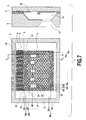
- Fig. 7 is a transverse cross sectional view of the vicinity of the nozzles of the liquid ejection head of the present embodiment.
- the valve supporting member 11 manufactured in the method described above is provided with a plurality of first holes 19 and second holes 18 in order to suppress, as much as possible, a change in dimensions of the valve supporting member 11, which may occur due to thermal expansion of the valve supporting member 11.
- the provision of these holes results from a consideration of adverse thermal influence caused during a heating process for curing an adhesive agent for attaching the valve supporting member 11 to the valve seats 12, or during a recoding operation.
- the first holes 19 have their centers respectively on lines LB3 to LBn-2, which are parallel with an arrangement direction of the movable valves 6 on the valve supporting member 11; and on lines LA1 to LAn, which are parallel with a direction perpendicular to the arrangement direction of the movable valves 6.
- the second holes 18 have their centers respectively on lines LB1, LB2, LBn-1 and LBn-2, which are parallel with the arrangement direction of the movable valves 6 on the valve supporting member 11, and on lines LA1 to LAn which are parallel with a direction perpendicular to the arrangement direction of the movable valves 6.
- the second holes 18 are arranged in a staggered manner.
- the second holes 18 are arranged in the staggered manner at left and right ends outside a group of the first holes 19 in the direction parallel with the arrangement direction of the movable valves 6.
- each of the second holes 18 is formed with a diameter smaller than that of each of the first holes 19.
- a larger portion made of a material in the valve supporting member 11 is left at the left and right ends.
- the strength of the valve supporting member 11 itself is enhanced.
- the valve supporting member 11 is prevented from being broken when separated from the wafer during the manufacturing.
- slits 20, which are chipped portions are respectively provided to the second holes 18 arranged on the lines LB1 and LBn.
- each of the second holes 18 on the line LB1 are provided with a slit 20 so as to communicate with a space between the closest two movable valves 6 to the second hole 18.
- each of the second holes 18 on the line LBn is provided with a slit 20 so as to form an opening at the end portion of the valve supporting member 11, the end portion being the closest to the second hole 18.
- the arrangement of chipped portions of the second holes 18, the first holes 19 and the slits 20 is provided particularly in consideration of the prevention of expansion of the valve supporting member 11 in the arrangement direction of the movable valves 6 (the direction indicated by an arrow B in Fig. 6). Specifically, in a case where a cutting plane of the valve supporting member 11 which is obtained by cutting at every line parallel with the line LB1 is viewed as a cross section, any cross section in any portion is not a single continuous cross section. This is because these second holes 18, the first holes 19 and the slits 20 are provided therein.
- the thermal influence on operations of the movable valves 6 during liquid ejection can be suppressed as much as possible by providing the second holes 18, the first holes 19 and the slits 20 in the above described manner.
- the dispersed arrangement of plural pieces of the second holes 18 and the first holes 19 allows the diameter of each of the holes to be reduced, and thereby, prevents the strength of the valve supporting member 11 to be extremely deteriorated.
- this configuration allows the valve supporting member 11 to absorb vibrations more easily, and thereby the valve supporting member 11 to absorb vibrations of the movable valves 6 during the liquid ejection.
- the vibrations of one of the movable valves 6 do not influence an operation of the different movable valves 6 adjacent to the concerned movable valve 6.
- Quadrangle holes are further provided in the valve supporting member 11.
- One type of the quadrangle holes is used for positioning the valve supporting member 11 on the valve seats 12, and the other type of the quadrangles is used for attaching and fixing the valve supporting member 11 on the valve seats 12.
- Each of the quadrangle holes 30 for positioning is a rectangle hole having the centerline on a corresponding one of the line LA 3 and LAn-2, and having its longitudinal direction in a direction of the centerline.
- the quadrangle holes 30 are provided so as to position the valve supporting member 11 at rear ends of the quadrangle holes 30 by supporting columns 32 made of the same material as that of the nozzle walls 5.
- the quadrangle holes 31 for attaching and fixing three quadrangles having their centerlines on the line LB7 are aligned between the two quadrangle holes 30.
- a "chipped portion" used in this specification means both of slits including a hole in a closed space and an open space as the one described above.
- Fig. 8 is a cross sectional view showing a structure of the periphery of one of the ejection ports 13 of the liquid ejection head of the present embodiment.
- a liquid is supplied to a supply orifice after passing through the common liquid chamber 16 as shown by arrows in Fig. 8.
- Fig. 9A is a view showing a state of one of the nozzles 14 before electric energy is applied to the heater 2. Since an air-bubble 21 (refer to Fig. 9B) is not yet generated, the movable valve 6 is kept in equilibrium. Then, Fig. 9B shows a state where the heater 2 generates heat when electric energy is applied thereto, and where then the air-bubble 21 is generated in the liquid.
- Fig. 9C is a view showing a moment when the liquid is just ejected from the ejection port 13.
- the air-bubble 21 shrinks as the pressure inside the air-bubble 21 becomes negative pressure.
- the movable valve 6 changes its position so as to return to the state shown in Fig. 9A, which is equilibrium, from the state shown in Fig. 9C.
- Fig. 10 is a plane view schematically showing the valve supporting member 11, and the chipped portions provided thereon in the embodiment of the present invention.
- the valve supporting member 11 includes a chipped portion P1 (a first chipped portion), a chipped portion P2 (a second chipped portion) which are provided with a predetermined distance interposed in between.
- the valve supporting member 11 includes an area W1 (a first area) .
- the area W1 is an area of the valve supporting member 11 which is positioned between the chipped portions P1 and P2, and which extends in a direction (the direction indicated by an arrow B in Fig. 10) crossing an ejection direction (the direction indicated by an arrow C in Fig. 10).
- the valve supporting member 11 includes a chipped portion P3 (a third chipped portion) and areas W2.
- the chipped portion P3 extends over an entire area in the direction indicated by the arrow C in the area W1.
- the chipped portions P1 and P2 are located in the areas W2, respectively, and the areas W2 extend in the direction indicated by the arrow B.
- the valve supporting member 11 further includes chipped portions P4 which include parts of the areas W2 (the second areas), respectively.
- the slits 20 are provided to the second holes 18 on the line LBn so as to form an opening at the end portion of the valve supporting members 11 closest to the second hole 18.
- the thermal expansion of the movable valves 6 does not affect a liquid ejection without providing the slits 20, since the slits 20 provided respectively in the second holes 18 on the LBn are far from the movable valves 6.
- the shape of a hole is not limited to a circular shape, and other shapes, for example, a polygonal including a quadrangle, a triangle or the like may be employed.
- first holes 19 and the second holes 18 are provided in a staggered manner in this embodiment, it is not limited to the staggered manner.
- the first holes 19 and the second holes 18 may be arranged in any manner so long as the operations of the movable valves 6 during liquid ejection are not affected by the thermal expansion of the valve supporting member 11.
- circular holes may be arranged in a curved line.
- first holes 19 and second holes 18 are provided in the valve supporting member 11 in this embodiment, it is not limited to this, and a single continuous hole may be provided.
- the slit 20 is provided to the second hole 18 corresponding to every second space between the movable valves 6 in this embodiment, the providing manner is not limited to this.
- the slit 20 may be provided at each supporting point 10.
- the two quadrangle holes 30 for positioning are provided in this embodiment, it is not limited to this. At least one quadrangle hole 30 may be provided. However, in a case where only one quadrangle hole 30 is provided, the displacement of the valve supporting member 11 in a rotation direction easily occurs when the valve supporting member 11 is positioned.
- the three quadrangle holes 31 for attaching and fixing are provided in this embodiment, it is not limited to this.
- the number of quadrangle holes 31 can be any number not less than one, as long as the valve supporting member 11 can be attached and fixed to the valve seats 12.
- a liquid ejection head capable of performing a stable ejection operation at high speed even when thermal expansion of a valve supporting member occurs during liquid ejection. This is because the liquid ejection head allows the thermal expansion to influence supported valves only to a small extent, and a highly accurate and stable adhesion state to be obtained.
- first holes, second holes and slits are provided in the valve supporting member.
Landscapes
- Engineering & Computer Science (AREA)
- Manufacturing & Machinery (AREA)
- Particle Formation And Scattering Control In Inkjet Printers (AREA)
Applications Claiming Priority (1)
| Application Number | Priority Date | Filing Date | Title |
|---|---|---|---|
| JP2006058413A JP2007230193A (ja) | 2006-03-03 | 2006-03-03 | 液体吐出ヘッド |
Publications (3)
| Publication Number | Publication Date |
|---|---|
| EP1829690A2 true EP1829690A2 (de) | 2007-09-05 |
| EP1829690A3 EP1829690A3 (de) | 2008-12-10 |
| EP1829690B1 EP1829690B1 (de) | 2010-11-24 |
Family
ID=38016409
Family Applications (1)
| Application Number | Title | Priority Date | Filing Date |
|---|---|---|---|
| EP07103386A Not-in-force EP1829690B1 (de) | 2006-03-03 | 2007-03-02 | Flüssigkeitsausstoßkopf |
Country Status (4)
| Country | Link |
|---|---|
| US (1) | US7434916B2 (de) |
| EP (1) | EP1829690B1 (de) |
| JP (1) | JP2007230193A (de) |
| DE (1) | DE602007010682D1 (de) |
Cited By (1)
| Publication number | Priority date | Publication date | Assignee | Title |
|---|---|---|---|---|
| EP2467438B2 (de) † | 2009-09-03 | 2020-01-29 | Sericol Limited | Drucktinte |
Families Citing this family (5)
| Publication number | Priority date | Publication date | Assignee | Title |
|---|---|---|---|---|
| JP2007230193A (ja) | 2006-03-03 | 2007-09-13 | Canon Finetech Inc | 液体吐出ヘッド |
| JP5248421B2 (ja) | 2009-06-22 | 2013-07-31 | ブラザー工業株式会社 | 液体吐出装置 |
| JP5661838B2 (ja) | 2012-04-25 | 2015-01-28 | キヤノンファインテック株式会社 | インク供給装置および記録装置 |
| JP5763699B2 (ja) | 2013-03-22 | 2015-08-12 | キヤノンファインテック株式会社 | 液体吐出ヘッドおよび液体吐出装置 |
| JP5806341B2 (ja) | 2013-03-22 | 2015-11-10 | キヤノンファインテック株式会社 | 液体吐出ヘッドおよび液体吐出装置 |
Family Cites Families (12)
| Publication number | Priority date | Publication date | Assignee | Title |
|---|---|---|---|---|
| JPS63197652A (ja) | 1987-02-13 | 1988-08-16 | Canon Inc | インクジエツト記録ヘツドおよびその製造方法 |
| US5278585A (en) * | 1992-05-28 | 1994-01-11 | Xerox Corporation | Ink jet printhead with ink flow directing valves |
| CN1121947C (zh) * | 1996-06-07 | 2003-09-24 | 佳能株式会社 | 喷液头和喷液设备以及制造喷液头的方法 |
| JP3432077B2 (ja) * | 1996-06-07 | 2003-07-28 | キヤノン株式会社 | 液体吐出ヘッド、液体吐出装置および液体吐出方法 |
| JPH1016243A (ja) | 1996-07-04 | 1998-01-20 | Canon Inc | 液体吐出ヘッドの製造方法およびその製造方法により得られた液体吐出ヘッド |
| DE69819976T2 (de) * | 1997-08-05 | 2004-09-02 | Canon K.K. | Flüssigkeitsausstosskopf, Substrat und Herstelllungsverfahren |
| JP3524340B2 (ja) * | 1997-08-26 | 2004-05-10 | キヤノン株式会社 | 液体吐出ヘッド |
| JP3907329B2 (ja) * | 1998-12-03 | 2007-04-18 | キヤノン株式会社 | 液体吐出ヘッドおよび液体吐出装置 |
| JP2004253738A (ja) * | 2003-02-21 | 2004-09-09 | Toshiba Corp | パッケージ基板及びフリップチップ型半導体装置 |
| JP4726501B2 (ja) | 2005-01-21 | 2011-07-20 | キヤノンファインテック株式会社 | インクジェット記録ヘッドおよびインクジェット記録装置 |
| JP2007230194A (ja) * | 2006-03-03 | 2007-09-13 | Canon Finetech Inc | インクジェット記録ヘッドおよび製造方法 |
| JP2007230193A (ja) | 2006-03-03 | 2007-09-13 | Canon Finetech Inc | 液体吐出ヘッド |
-
2006
- 2006-03-03 JP JP2006058413A patent/JP2007230193A/ja not_active Ceased
-
2007
- 2007-02-26 US US11/678,878 patent/US7434916B2/en not_active Expired - Fee Related
- 2007-03-02 DE DE602007010682T patent/DE602007010682D1/de active Active
- 2007-03-02 EP EP07103386A patent/EP1829690B1/de not_active Not-in-force
Cited By (1)
| Publication number | Priority date | Publication date | Assignee | Title |
|---|---|---|---|---|
| EP2467438B2 (de) † | 2009-09-03 | 2020-01-29 | Sericol Limited | Drucktinte |
Also Published As
| Publication number | Publication date |
|---|---|
| US20070206063A1 (en) | 2007-09-06 |
| US7434916B2 (en) | 2008-10-14 |
| EP1829690A3 (de) | 2008-12-10 |
| JP2007230193A (ja) | 2007-09-13 |
| DE602007010682D1 (de) | 2011-01-05 |
| EP1829690B1 (de) | 2010-11-24 |
Similar Documents
| Publication | Publication Date | Title |
|---|---|---|
| US10195851B2 (en) | Printhead die | |
| EP1829690B1 (de) | Flüssigkeitsausstoßkopf | |
| US8454131B2 (en) | Ink jet print head | |
| US11040534B2 (en) | Liquid ejecting head and liquid ejecting apparatus | |
| JP2003063012A (ja) | 液体吐出ヘッド | |
| KR20130002276A (ko) | 액체 분사 헤드, 액체 분사 장치 및 액체 분사 헤드의 제조 방법 | |
| JP3625357B2 (ja) | 液体輸送方法および液体輸送装置 | |
| AU4115699A (en) | Liquid discharging head and liquid discharging method | |
| EP3634763B1 (de) | Flüssigkeitsausstossvorrichtung mit verringertem überlagerung, entsprechendes betriebsverfahren und herstellungsverfahren | |
| CN101977773B (zh) | 一种打印头和用于制造打印头的方法 | |
| JP2007230132A (ja) | インクジェット記録ヘッド | |
| EP1829689B1 (de) | Tintenstrahldruckkopf und Herstellungsverfahren dafür | |
| CN101638003B (zh) | 液滴排出头和装配有该液滴排出头的液滴排出装置 | |
| HK1108411A (en) | Liquid ejection head | |
| WO2003055686A1 (en) | Liquid delivering device and liquid delivering method | |
| HK1108412A (en) | Inkjet printing head and method of manufacturing the same | |
| US7637596B2 (en) | Print head with liquid channels having movable valves | |
| CN113272146B (zh) | 流体供给孔端口尺寸 | |
| JP2007230192A (ja) | 液体吐出ヘッドおよびその製造方法 | |
| US9004651B2 (en) | Thermo-pneumatic actuator working fluid layer | |
| JP2009090495A (ja) | インクジェット記録ヘッドおよびインクジェット記録ヘッドの製造方法 | |
| JP2009226911A (ja) | 液体吐出ヘッド及び液体吐出ヘッドの製造方法 | |
| JP2009190315A (ja) | 液体吐出ヘッド | |
| JP2010120184A (ja) | 液体吐出ヘッド | |
| JP2007283632A (ja) | インクジェット記録ヘッドおよびインクジェット記録装置 |
Legal Events
| Date | Code | Title | Description |
|---|---|---|---|
| PUAI | Public reference made under article 153(3) epc to a published international application that has entered the european phase |
Free format text: ORIGINAL CODE: 0009012 |
|
| 17P | Request for examination filed |
Effective date: 20070302 |
|
| AK | Designated contracting states |
Kind code of ref document: A2 Designated state(s): AT BE BG CH CY CZ DE DK EE ES FI FR GB GR HU IE IS IT LI LT LU LV MC MT NL PL PT RO SE SI SK TR |
|
| AX | Request for extension of the european patent |
Extension state: AL BA HR MK YU |
|
| REG | Reference to a national code |
Ref country code: HK Ref legal event code: DE Ref document number: 1108411 Country of ref document: HK |
|
| PUAL | Search report despatched |
Free format text: ORIGINAL CODE: 0009013 |
|
| AK | Designated contracting states |
Kind code of ref document: A3 Designated state(s): AT BE BG CH CY CZ DE DK EE ES FI FR GB GR HU IE IS IT LI LT LU LV MC MT NL PL PT RO SE SI SK TR |
|
| AX | Request for extension of the european patent |
Extension state: AL BA HR MK RS |
|
| 17Q | First examination report despatched |
Effective date: 20090422 |
|
| RAP1 | Party data changed (applicant data changed or rights of an application transferred) |
Owner name: CANON FINETECH INC. |
|
| AKX | Designation fees paid |
Designated state(s): DE FR GB |
|
| GRAP | Despatch of communication of intention to grant a patent |
Free format text: ORIGINAL CODE: EPIDOSNIGR1 |
|
| GRAS | Grant fee paid |
Free format text: ORIGINAL CODE: EPIDOSNIGR3 |
|
| GRAA | (expected) grant |
Free format text: ORIGINAL CODE: 0009210 |
|
| AK | Designated contracting states |
Kind code of ref document: B1 Designated state(s): DE FR GB |
|
| REG | Reference to a national code |
Ref country code: GB Ref legal event code: FG4D |
|
| REF | Corresponds to: |
Ref document number: 602007010682 Country of ref document: DE Date of ref document: 20110105 Kind code of ref document: P |
|
| PGFP | Annual fee paid to national office [announced via postgrant information from national office to epo] |
Ref country code: DE Payment date: 20110330 Year of fee payment: 5 |
|
| PLBE | No opposition filed within time limit |
Free format text: ORIGINAL CODE: 0009261 |
|
| STAA | Information on the status of an ep patent application or granted ep patent |
Free format text: STATUS: NO OPPOSITION FILED WITHIN TIME LIMIT |
|
| 26N | No opposition filed |
Effective date: 20110825 |
|
| GBPC | Gb: european patent ceased through non-payment of renewal fee |
Effective date: 20110302 |
|
| REG | Reference to a national code |
Ref country code: DE Ref legal event code: R097 Ref document number: 602007010682 Country of ref document: DE Effective date: 20110825 |
|
| REG | Reference to a national code |
Ref country code: FR Ref legal event code: ST Effective date: 20111130 |
|
| PG25 | Lapsed in a contracting state [announced via postgrant information from national office to epo] |
Ref country code: FR Free format text: LAPSE BECAUSE OF NON-PAYMENT OF DUE FEES Effective date: 20110331 |
|
| PG25 | Lapsed in a contracting state [announced via postgrant information from national office to epo] |
Ref country code: GB Free format text: LAPSE BECAUSE OF NON-PAYMENT OF DUE FEES Effective date: 20110302 |
|
| REG | Reference to a national code |
Ref country code: DE Ref legal event code: R119 Ref document number: 602007010682 Country of ref document: DE Effective date: 20121002 |
|
| REG | Reference to a national code |
Ref country code: HK Ref legal event code: WD Ref document number: 1108411 Country of ref document: HK |
|
| PG25 | Lapsed in a contracting state [announced via postgrant information from national office to epo] |
Ref country code: DE Free format text: LAPSE BECAUSE OF NON-PAYMENT OF DUE FEES Effective date: 20121002 |