EP1829763A2 - Dispositif destiné au transport de charges - Google Patents
Dispositif destiné au transport de charges Download PDFInfo
- Publication number
- EP1829763A2 EP1829763A2 EP07004288A EP07004288A EP1829763A2 EP 1829763 A2 EP1829763 A2 EP 1829763A2 EP 07004288 A EP07004288 A EP 07004288A EP 07004288 A EP07004288 A EP 07004288A EP 1829763 A2 EP1829763 A2 EP 1829763A2
- Authority
- EP
- European Patent Office
- Prior art keywords
- guideway
- guide means
- loads
- rollers
- guide
- Prior art date
- Legal status (The legal status is an assumption and is not a legal conclusion. Google has not performed a legal analysis and makes no representation as to the accuracy of the status listed.)
- Withdrawn
Links
Images


Classifications
-
- B—PERFORMING OPERATIONS; TRANSPORTING
- B62—LAND VEHICLES FOR TRAVELLING OTHERWISE THAN ON RAILS
- B62B—HAND-PROPELLED VEHICLES, e.g. HAND CARTS OR PERAMBULATORS; SLEDGES
- B62B1/00—Hand carts having only one axis carrying one or more transport wheels; Equipment therefor
- B62B1/002—Hand carts having only one axis carrying one or more transport wheels; Equipment therefor convertible from a one-axled vehicle to a two-axled vehicle
-
- B—PERFORMING OPERATIONS; TRANSPORTING
- B60—VEHICLES IN GENERAL
- B60F—VEHICLES FOR USE BOTH ON RAIL AND ON ROAD; VEHICLES CAPABLE OF TRAVELLING IN OR ON DIFFERENT MEDIA, e.g. AMPHIBIOUS VEHICLES
- B60F1/00—Vehicles for use both on rail and on road; Conversions therefor
- B60F1/02—Vehicles for use both on rail and on road; Conversions therefor with rail and road wheels on the same axle
-
- B—PERFORMING OPERATIONS; TRANSPORTING
- B60—VEHICLES IN GENERAL
- B60F—VEHICLES FOR USE BOTH ON RAIL AND ON ROAD; VEHICLES CAPABLE OF TRAVELLING IN OR ON DIFFERENT MEDIA, e.g. AMPHIBIOUS VEHICLES
- B60F1/00—Vehicles for use both on rail and on road; Conversions therefor
- B60F1/04—Vehicles for use both on rail and on road; Conversions therefor with rail and road wheels on different axles
-
- B—PERFORMING OPERATIONS; TRANSPORTING
- B62—LAND VEHICLES FOR TRAVELLING OTHERWISE THAN ON RAILS
- B62B—HAND-PROPELLED VEHICLES, e.g. HAND CARTS OR PERAMBULATORS; SLEDGES
- B62B1/00—Hand carts having only one axis carrying one or more transport wheels; Equipment therefor
- B62B1/10—Hand carts having only one axis carrying one or more transport wheels; Equipment therefor in which the load is intended to be transferred totally to the wheels
- B62B1/12—Hand carts having only one axis carrying one or more transport wheels; Equipment therefor in which the load is intended to be transferred totally to the wheels involving parts being adjustable, collapsible, attachable, detachable, or convertible
- B62B1/125—Hand carts having only one axis carrying one or more transport wheels; Equipment therefor in which the load is intended to be transferred totally to the wheels involving parts being adjustable, collapsible, attachable, detachable, or convertible by means of telescoping elements
-
- B—PERFORMING OPERATIONS; TRANSPORTING
- B62—LAND VEHICLES FOR TRAVELLING OTHERWISE THAN ON RAILS
- B62B—HAND-PROPELLED VEHICLES, e.g. HAND CARTS OR PERAMBULATORS; SLEDGES
- B62B3/00—Hand carts having more than one axis carrying transport wheels; Steering devices therefor; Equipment therefor
- B62B3/008—Hand carts having more than one axis carrying transport wheels; Steering devices therefor; Equipment therefor having more than two axes
Definitions
- the invention relates to a device for transporting loads with means for receiving the load to be transported (receiving means) and with first rollers on which the device rolls when transporting the load on a substrate.
- the invention further relates to an arrangement of a guideway and such a device.
- sack trucks For transporting loads so-called sack trucks are known. Other than her name suggests, sack trucks can not only transport sacks, but also crates, large electrical appliances and the like. Sack trucks are an ideal means of transport in one plane and in special forms they are also suitable for overcoming steps.
- sliding carriages are known for transporting loads on guideways.
- inclined elevators are known which can be used, for example, for moving to transport boxes or pieces of furniture from the street level to a higher level, without it being necessary to carry the individual boxes or pieces of furniture over a staircase.
- the invention is therefore based on the object to propose a device for transporting loads, which is suitable, in conjunction with a guideway, for example in the form of a ladder, to form a technically simple and at the same time safe inclined lift.
- the device for transporting loads of the type mentioned comprises guide means which are suitable and adapted to guide the device when moving the device along a guide track with complementary to the guide means of the device guide means.
- a device according to the invention for transporting loads can be used both as a sack truck, for which the device has the first rollers, and be used as a carriage, for example, an inclined elevator, for which purpose the device comprises the guide means, with which the connection to the guideway can be made.
- the guide means of the device according to the invention are arranged in two parallel planes, wherein the planes come to rest on two sides of the guide means of the guideway when the device according to the invention is used together with a guideway.
- the guide means are constantly in both planes. It is sufficient if at least a part of the guide means can be pivoted into the plane in which they must lie in use together with a guideway.
- the guiding means of the device are preferably further rollers.
- the receiving means of a device according to the invention may comprise two L-shaped elements, which are arranged at a distance from each other. On the L-shaped elements surface elements may be attached, on which the loads to be transported can be placed.
- the first rollers and / or the other rollers may be rotatably mounted on the receiving means, in particular on the L-shaped elements of the receiving means.
- the device according to the invention may comprise at least one handle for engaging a user when moving the device on the ground.
- These handles may include a pair of the first handles, which are preferably pivotally mounted to the receiving means.
- a first pair of guide means of the device may be attached to the first handle and optionally pivotable together with these handles.
- the device may comprise a bracket, which is preferably mounted vertically adjustable on the receiving means, in particular on the L-shaped elements of the receiving means.
- the bracket can be advantageously fixed by suitable means in two different locking positions.
- the apparatus may further comprise means for engaging a drive device to translate the device along the guideway. It may be an eyelet or the like, in which a rope can be hung, which is part of a pulley or winch.
- two parallel spaced apart spars may be suitable, which form the guide means of the guideway.
- the guideway may be a ladder.
- the guide means of the device can embrace the rails of the guideway.
- the arrangement of a device according to the invention and a guideway may comprise a drive device for displacing the device according to the invention along the guideway.
- This drive device may comprise a pulley and / or a motor.
- the device 1 shown in FIGS. 1 to 6, which is basically a sack truck, has means for receiving the loads to be transported (receiving means) on which first rollers 2 are rotatably mounted. About these roles 2, the device 1 of the invention is supported during a displacement of the device 1 according to the invention on a substrate, if the device 1 is used as a hand truck.
- the receiving means 4 which form the main part of the device 1 according to the invention, comprise two L-shaped elements 41.
- the L-shaped elements 41 are connected to one another via transverse struts 44 and 45.
- the one transverse strut 44 is attached in the region of the apex of the L-shaped elements 41, while the other Cross strut 45 at the upper end of the position of use in the form of a sack truck upwardly projecting leg of the L-shaped elements 41 between the two L-shaped elements 41 is mounted.
- the space between the two L-shaped elements is covered by surface elements 42, 43. On these surface elements 42, 43, the load to be transported can be launched, or ajar.
- a first handle 51 is attached, which together form a pair of handles.
- These handles which are explained in more detail with reference to FIG. 4, are pivotally mounted on the legs.
- a guide element in the form of a roller 31 is mounted, which is necessary for the displacement of the device 1 according to the invention along a guideway.
- a further guide element 32 is mounted in each case at the lower end of the longer leg in the apex region coaxial with the first rollers 2.
- These guide elements 32 and these guide elements 32 are formed by rollers -
- Third guide elements 33, also in the form of rollers 33 are rotatably mounted at the upper end of the longer leg.
- the rollers 31, 32, 33 provided as guide means lie in two planes lying parallel to one another at a distance from one another.
- the first guide elements 31 lie in the pivoted-out position of the handles 51 in the first plane, while the second and the third guide elements 32, 33 lie in the second plane.
- the two planes are respectively arranged on two sides of the guideway.
- a second handle in the form of a bracket 52 is provided.
- This bracket 52 which has the shape of an upside-down U, engages with its free leg ends in the upper ends of the longer legs of the L-shaped elements 41 and is slidably mounted in these, so that this second handle 52 is height adjustable.
- a tab 6 is fixed, which has a bore into which a rope or the like can be hung.
- the rope may be part of a drive device which pulls the device 1 according to the invention together with a guideway along the guideway in use. If the guideway is arranged at an angle, the arrangement of the guideway and the device according to the invention can be used as an inclined elevator.
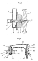
- the first roles. 2 and the second guide means 32 are respectively. connected via a screw 22 with the receiving means 4.
- the first rollers 2 and the second guide means 32 forming rollers 32 and have for this purpose central bores, in which bushings 21, 34 provided with externally circumferential collars are inserted. These bushings 21 and 34 are penetrated by the screws 22, which continue to pass through a hole in the L-shaped elements 41 and are each screwed into a welded in the lower cross member 44 nut.
- the screws 22 clamp the bushes 21 and 34 against the L-shaped element 41, so that there is a rigid axis on which the rollers 2 and 32 can rotate freely.
- the rotation of the rollers 2 and 32 is possible independently of each other.
- the rollers 2, 32 are through the sockets provided bundles not together and are not on the L-shaped elements 41 of the receiving means 4 at.
- the first handles (S1, FIG. 4) have an approximately L-shaped two-part housing 511, 512.
- the lower housing part 511 is pivotably attached to the L-shaped elements 41 by means of a screw 515.
- the pivoting position can be determined via a cam 517 and two corresponding recesses in the L-shaped element 41. For pivoting this cam 517 must be lifted out of the corresponding recess in the L-shaped elements 41.
- the first handle 51 must be pulled outward without the connection between the handle and the L-shaped member 41 is released.
- the screws 515 each pass through two bushes 514, 513, which are arranged one behind the other and which have an outer peripheral collar and are identical to the bushes 34 in the region of the second guide elements 32.
- the bushes 513 engage in a respective bore in the L-shaped elements 41 and the end of the screws 515 passes through the L-shaped element 41.
- the screws are fixed to the elements 41 with one nut each.
- the screws 515 and the two sockets 513, 514 are braced against the L-shaped element 41. Between the two coils of the sockets 513, 514, a spring 516 and a part of the housing lower part 511 is respectively clamped.
- the springs 516 are based on the one hand on the collar of the sockets 514 and on the other on the part of the housing bases 511. Since the housing bases are otherwise not secured, the housing bases can be moved against the pressure of the springs on the screws 515 and on the sockets 513, 514. This makes it possible pull the handles 51 outward and lift the cams 517 out of the recesses in the L-shaped members 41.
- the first formed as a roller 31 guide means of the device are mounted.
- the screws pass through a corresponding receptacle at the end of the housing bases 511, in which the bushes 315 are inserted.
- the sockets are identical to the previously mentioned sockets 513, 514 and 34.
- the rollers 31 are attached, wherein the bushings protrude from the central bore of the rollers 31.
- the thread of the screws 312 protrudes from the central bore of the rollers 31 and also out of the bushings, so that each nut is screwed with the interposition of the washers 313 on the free end of the screws to the rollers 31 freely rotatable with the housing base 511 connect to.
- Cover caps 311 protect the nuts from unintentional release.
- an upper housing part 512 covers the lower housing part and the screw heads of the screws 312 and 515, so that they can not be solved unintentionally.
- the third guide means (FIG. 5) are also fastened by means of a respective screw 332, washers 333, one nut 334 and one bush 335 each.
- the attachment takes place at the upper ends of the L-shaped elements 41 and cross member 45.
- nuts 334 are welded.
- the screws 332 are screwed, which pass through the sockets 335.
- the bushes are supported with their outer collar on the outside of the L-shaped member 41.
- On the bushes 335 is the wheel 33rd attached, which can rotate freely on the respective socket. Depending on a cover 331 prevents the screws can be unintentionally solved.
- the second handle in the form of the bracket 52 is passed through a respective hole in a cap 47, which are inserted into the upper ends of the L-shaped elements 41, with their legs.
- pistons 521 are fixed, which guide the bracket inside the L-shaped elements 41.
- the intended for attachment of the first handle nut, in which the screw 515 is screwed, is used on the inside of the L-shaped member 41 as a stop for the piston 521, so that the bracket no further than in the position shown in Fig. 6 the L-shaped elements 41 can be pulled out. This ensures that a sufficient power transmission between the bracket 52 and the L-shaped elements 41 is also possible for transporting heavy loads.
Landscapes
- Engineering & Computer Science (AREA)
- Transportation (AREA)
- Mechanical Engineering (AREA)
- Chemical & Material Sciences (AREA)
- Combustion & Propulsion (AREA)
- Handcart (AREA)
- Rollers For Roller Conveyors For Transfer (AREA)
- Framework For Endless Conveyors (AREA)
Applications Claiming Priority (1)
| Application Number | Priority Date | Filing Date | Title |
|---|---|---|---|
| DE200610010225 DE102006010225A1 (de) | 2006-03-02 | 2006-03-02 | Vorrichtung zum Transportieren von Lasten |
Publications (2)
| Publication Number | Publication Date |
|---|---|
| EP1829763A2 true EP1829763A2 (fr) | 2007-09-05 |
| EP1829763A3 EP1829763A3 (fr) | 2008-04-16 |
Family
ID=38068409
Family Applications (1)
| Application Number | Title | Priority Date | Filing Date |
|---|---|---|---|
| EP07004288A Withdrawn EP1829763A3 (fr) | 2006-03-02 | 2007-03-02 | Dispositif destiné au transport de charges |
Country Status (2)
| Country | Link |
|---|---|
| EP (1) | EP1829763A3 (fr) |
| DE (1) | DE102006010225A1 (fr) |
Cited By (2)
| Publication number | Priority date | Publication date | Assignee | Title |
|---|---|---|---|---|
| US11505226B1 (en) | 2021-06-25 | 2022-11-22 | Anthony Frank Taranto | Ground and ladder transport apparatus |
| US12546166B2 (en) | 2024-03-19 | 2026-02-10 | M.U.L.E. Inc. | Ladder trolley and related method |
Families Citing this family (2)
| Publication number | Priority date | Publication date | Assignee | Title |
|---|---|---|---|---|
| DE102007007052A1 (de) | 2007-02-08 | 2008-08-21 | Hailo-Werk Rudolf Loh Gmbh & Co. Kg | Anordnung aus einer Leiter, einem Wagen und einem Lastenträger sowie Wagen und Lastenträger |
| JP7849185B2 (ja) * | 2022-02-21 | 2026-04-21 | Jr西日本電気テック株式会社 | 運搬車 |
Family Cites Families (4)
| Publication number | Priority date | Publication date | Assignee | Title |
|---|---|---|---|---|
| DD67669A1 (de) * | 1968-05-02 | 1969-06-20 | Manfred Schmeisser | Transportkarre |
| US3666054A (en) * | 1970-02-24 | 1972-05-30 | Frank L Ellings | Ladder dolly and winch |
| US5275256A (en) * | 1992-05-28 | 1994-01-04 | Ellzey Floyd D | Ladder carriage apparatus |
| JP2002178926A (ja) * | 2000-12-12 | 2002-06-26 | Matsuzaki:Kk | 運搬台車 |
-
2006
- 2006-03-02 DE DE200610010225 patent/DE102006010225A1/de not_active Ceased
-
2007
- 2007-03-02 EP EP07004288A patent/EP1829763A3/fr not_active Withdrawn
Cited By (2)
| Publication number | Priority date | Publication date | Assignee | Title |
|---|---|---|---|---|
| US11505226B1 (en) | 2021-06-25 | 2022-11-22 | Anthony Frank Taranto | Ground and ladder transport apparatus |
| US12546166B2 (en) | 2024-03-19 | 2026-02-10 | M.U.L.E. Inc. | Ladder trolley and related method |
Also Published As
| Publication number | Publication date |
|---|---|
| EP1829763A3 (fr) | 2008-04-16 |
| DE102006010225A1 (de) | 2007-09-06 |
Similar Documents
| Publication | Publication Date | Title |
|---|---|---|
| DE69511443T2 (de) | Zusammenlegbare Unterstützung für Gewindeschneidmaschinen | |
| DE10147400B4 (de) | Sackkarren | |
| EP3103712B1 (fr) | Scooter pliable | |
| AT517363B1 (de) | Vorrichtung zum Transportieren von Fahrrädern | |
| DE102014102371A1 (de) | Anhänger für einen Routenzug | |
| EP0079852A2 (fr) | Echelle à usages multiples | |
| DE102017001747B4 (de) | Zusammenklappbarer Einkaufs- und Transportwagen | |
| EP1829763A2 (fr) | Dispositif destiné au transport de charges | |
| DE102019006854B4 (de) | Vorrichtung zum Halten eines Zweiradfahrzeuges in einer aufrechten Position | |
| DE2947904C2 (de) | Vorrichtung zum wahlweisen Absetzen von transportablen Behältern, Maschinen oder Geräten auf der kippbaren Ladepritsche eines Lastfahrzeuges oder auf dem Boden | |
| DE10029159A1 (de) | Vorrichtung zum Handhaben von plattenförmigen Werkstücken, insbesondere von Türen | |
| DE10311605A1 (de) | Hebeeinrichtung | |
| EP2554461B1 (fr) | Support de montage pour motos | |
| DE202014100556U1 (de) | Steiggerät mit Verriegelungsmechanismus | |
| EP2640557B1 (fr) | Table de travail, en particulier pour les ateliers | |
| AT525051B1 (de) | Vorrichtung zum Transport eines Gegenstandes | |
| DE102021110421B3 (de) | Handwagen zum direkten Verladen in ein Kraftfahrzeug | |
| EP3144264B1 (fr) | Dispositif de levage | |
| DE10208813B4 (de) | Hubroller | |
| AT12135U1 (de) | Holzspalter | |
| DE102006011852B3 (de) | Fahrgerät für eine Krankentrage oder Bahre | |
| DE102014114577A1 (de) | Sackkarre | |
| AT409749B (de) | Sackkarren | |
| DE2753143C3 (de) | Hubwagen für Fahrzeuge, insbesondere Kraftfahrzeuge | |
| DE52339C (de) | Fahrbare Ausziehleiter |
Legal Events
| Date | Code | Title | Description |
|---|---|---|---|
| PUAI | Public reference made under article 153(3) epc to a published international application that has entered the european phase |
Free format text: ORIGINAL CODE: 0009012 |
|
| AK | Designated contracting states |
Kind code of ref document: A2 Designated state(s): AT BE BG CH CY CZ DE DK EE ES FI FR GB GR HU IE IS IT LI LT LU LV MC MT NL PL PT RO SE SI SK TR |
|
| AX | Request for extension of the european patent |
Extension state: AL BA HR MK YU |
|
| PUAL | Search report despatched |
Free format text: ORIGINAL CODE: 0009013 |
|
| AK | Designated contracting states |
Kind code of ref document: A3 Designated state(s): AT BE BG CH CY CZ DE DK EE ES FI FR GB GR HU IE IS IT LI LT LU LV MC MT NL PL PT RO SE SI SK TR |
|
| AX | Request for extension of the european patent |
Extension state: AL BA HR MK RS |
|
| AKX | Designation fees paid | ||
| STAA | Information on the status of an ep patent application or granted ep patent |
Free format text: STATUS: THE APPLICATION IS DEEMED TO BE WITHDRAWN |
|
| 18D | Application deemed to be withdrawn |
Effective date: 20081017 |
|
| REG | Reference to a national code |
Ref country code: DE Ref legal event code: 8566 |