EP1829765A2 - Fahrzeuglenkung - Google Patents
Fahrzeuglenkung Download PDFInfo
- Publication number
- EP1829765A2 EP1829765A2 EP07103281A EP07103281A EP1829765A2 EP 1829765 A2 EP1829765 A2 EP 1829765A2 EP 07103281 A EP07103281 A EP 07103281A EP 07103281 A EP07103281 A EP 07103281A EP 1829765 A2 EP1829765 A2 EP 1829765A2
- Authority
- EP
- European Patent Office
- Prior art keywords
- clutch
- steering
- engagement
- reaction force
- control
- Prior art date
- Legal status (The legal status is an assumption and is not a legal conclusion. Google has not performed a legal analysis and makes no representation as to the accuracy of the status listed.)
- Granted
Links
- 230000008859 change Effects 0.000 claims description 48
- 238000001514 detection method Methods 0.000 claims description 19
- 238000000034 method Methods 0.000 claims description 15
- 230000004044 response Effects 0.000 claims description 9
- 230000007246 mechanism Effects 0.000 abstract description 22
- 238000012545 processing Methods 0.000 description 38
- 230000006399 behavior Effects 0.000 description 15
- 230000005856 abnormality Effects 0.000 description 14
- 230000006870 function Effects 0.000 description 12
- 230000000694 effects Effects 0.000 description 9
- 230000007423 decrease Effects 0.000 description 8
- 238000005516 engineering process Methods 0.000 description 6
- 230000008569 process Effects 0.000 description 5
- 239000000470 constituent Substances 0.000 description 4
- 238000004891 communication Methods 0.000 description 3
- 238000011144 upstream manufacturing Methods 0.000 description 3
- 238000010586 diagram Methods 0.000 description 2
- 238000012986 modification Methods 0.000 description 2
- 230000004048 modification Effects 0.000 description 2
- 238000012546 transfer Methods 0.000 description 2
- 206010000210 abortion Diseases 0.000 description 1
- 238000007792 addition Methods 0.000 description 1
- 238000013459 approach Methods 0.000 description 1
- 230000005540 biological transmission Effects 0.000 description 1
- 230000000052 comparative effect Effects 0.000 description 1
- 238000013461 design Methods 0.000 description 1
- 230000009977 dual effect Effects 0.000 description 1
- 230000007257 malfunction Effects 0.000 description 1
- 238000005259 measurement Methods 0.000 description 1
- 238000004092 self-diagnosis Methods 0.000 description 1
Images







Classifications
-
- B—PERFORMING OPERATIONS; TRANSPORTING
- B62—LAND VEHICLES FOR TRAVELLING OTHERWISE THAN ON RAILS
- B62D—MOTOR VEHICLES; TRAILERS
- B62D5/00—Power-assisted or power-driven steering
- B62D5/001—Mechanical components or aspects of steer-by-wire systems, not otherwise provided for in this maingroup
-
- B—PERFORMING OPERATIONS; TRANSPORTING
- B62—LAND VEHICLES FOR TRAVELLING OTHERWISE THAN ON RAILS
- B62D—MOTOR VEHICLES; TRAILERS
- B62D5/00—Power-assisted or power-driven steering
- B62D5/001—Mechanical components or aspects of steer-by-wire systems, not otherwise provided for in this maingroup
- B62D5/003—Backup systems, e.g. for manual steering
-
- B—PERFORMING OPERATIONS; TRANSPORTING
- B62—LAND VEHICLES FOR TRAVELLING OTHERWISE THAN ON RAILS
- B62D—MOTOR VEHICLES; TRAILERS
- B62D5/00—Power-assisted or power-driven steering
- B62D5/04—Power-assisted or power-driven steering electrical, e.g. using an electric servo-motor connected to, or forming part of, the steering gear
- B62D5/0457—Power-assisted or power-driven steering electrical, e.g. using an electric servo-motor connected to, or forming part of, the steering gear characterised by control features of the drive means as such
- B62D5/0475—Controlling other elements
- B62D5/0478—Clutches
-
- B—PERFORMING OPERATIONS; TRANSPORTING
- B62—LAND VEHICLES FOR TRAVELLING OTHERWISE THAN ON RAILS
- B62D—MOTOR VEHICLES; TRAILERS
- B62D5/00—Power-assisted or power-driven steering
- B62D5/04—Power-assisted or power-driven steering electrical, e.g. using an electric servo-motor connected to, or forming part of, the steering gear
- B62D5/0457—Power-assisted or power-driven steering electrical, e.g. using an electric servo-motor connected to, or forming part of, the steering gear characterised by control features of the drive means as such
- B62D5/0481—Power-assisted or power-driven steering electrical, e.g. using an electric servo-motor connected to, or forming part of, the steering gear characterised by control features of the drive means as such monitoring the steering system, e.g. failures
Definitions
- the present invention generally relates to vehicle steering and particularly, but not exclusively, to a vehicle steering control apparatus for a steer-by-wire system provided with a clutch for mechanically connecting and disconnecting a driver operating unit configured to be operated by a driver and a steering unit configured to steer a steered wheel to and from each other. Aspects of the invention also relate to a method and to a vehicle.
- a clutch is provided as a backup mechanism for mechanically connecting the steering wheel and the steering mechanism.
- the clutch is connected immediately and the SBW control is aborted. If, for example, the reaction force actuator fails, once the steering wheel starts moving due to operation by the driver, the steering wheel will rotate easily until the clutch is completely engaged. Also until engagement of the clutch, a normal steering actuator will continue to operate in accordance with the rotary operation of the steering wheel, i.e., in accordance with the steering wheel angle value detected by a steering wheel angle sensor.
- the steered wheels may turn much more sharply than the driver intends causing an undesirable vehicle behavior.
- the control gain of the steering actuator is lowered or set to zero for a prescribed amount of time in order to restrict the operation of the steering actuator during the period from when the failure is detected until the clutch is connected.
- the prescribed amount of time is set in advance to a value that accurately reflects the time required for the clutch to connect (engage).
- the prescribed amount of time is determined by experimentally measuring the clutch engagement (connection) time and using, for example, the largest value from among a plurality of data.
- the steering angle is held constant during the prescribed period that the clutch is estimated to be in the process of becoming engaged. If the actual time required for the clutch to engage is shorter than the prescribed amount of time, then the steering angle will remain held even after the clutch is connected. Consequently, during the period from when the clutch actually engages until the prescribed amount of time elapses, the steering wheel will be connected directly to the steered wheels through the clutch and a reaction force will develop which holds the steering wheel in place, resulting in an unnatural steering feel for the driver.
- Embodiments of the invention may provide a vehicle steering control apparatus that can accurately determine when the clutch has actually engaged regardless of variations in the clutch engagement time and smoothly shift to a steering wheel operation mode immediately after the clutch has actually engaged.
- a vehicle steering control apparatus comprising a driver operating unit configured to be operated by a driver, a steering unit arranged to be mechanically separated from the driver operating unit and configured to turn at least one steered wheel in response to an operating state from the driver operating unit, an operating torque detector operable to detect the operating torque applied to the driver operating unit, a clutch operable to mechanically connect and disconnect the driver operating unit and the steering unit to and from each other, a clutch engagement command issuing section configured to issue an engagement command to the clutch when the clutch is disengaged and a clutch engaging condition is satisfied and a clutch engagement determining section configured to determine that the clutch is in an engaged state upon detecting an increase in the operating torque applied to the driver operating unit after the engagement command has been issued to the clutch.
- the apparatus may comprise a clutch engagement determination threshold value setting section configured to set a clutch engagement determination threshold value, the clutch engagement determining section being configured to determine that the clutch is in the engaged state when an operating torque detection value from the operating torque detector exceeds the clutch engagement determination threshold value after the engagement command has been issued to the clutch.
- the apparatus may comprise a relative angular velocity detector configured and arranged to detect a relative angular velocity between the driver operating unit and the steering unit, wherein the clutch engagement determination threshold value setting section is configured to set the clutch engagement determination threshold value such that the faster the relative angular velocity is, the smaller the clutch engagement determination threshold value is.
- the apparatus comprises a relative torque change rate detector configured and arranged to detect a relative torque change rate between the driver operating unit and the steering unit.
- the clutch engagement determination threshold value setting section may be configured to set the clutch engagement determination threshold value such that as the relative torque change rate increases, the clutch engagement determination threshold value becomes smaller.
- the apparatus may comprise a relative angular velocity detector configured and arranged to detect a relative angular velocity between the driver operating unit and the steering unit, a relative torque change rate detector configured and arranged to detect a relative torque change rate between the driver operating unit and the steering unit, a first clutch engagement determination threshold value setting section configured to set a relative angular velocity threshold value such that as the relative angular velocity increases, the relative angular velocity threshold value becomes smaller, and a second clutch engagement determination threshold value setting section configured to set a relative torque change rate threshold value such that as the relative torque change rate increases, the relative torque change rate threshold value becomes smaller.
- the clutch engagement determining section may be configured to set the clutch engagement determination threshold value to whichever of the relative angular velocity threshold value and the relative torque change rate threshold value is smaller.
- the apparatus comprises an operating torque change rate detector configured and arranged to detect a change rate of the operating torque and a clutch engagement determination threshold value setting section configured to set a clutch engagement determination threshold value.
- the clutch engagement determining section may be configured to determine that the clutch is in the engaged state when an operating torque change rate detection value from the operating torque change rate detector exceeds the clutch engagement determination threshold value after the engagement command has been issued to the clutch.
- the apparatus may comprise a first failure determining section configured to detect if a reaction force component failure has occurred and a clutch engagement transitional steering controller configured to switch from a steer-by-wire control to a vehicle behavior suppressing steering control during a period from when the engagement command is issued in response a determination to that the steering reaction force component failure has occurred until the clutch engagement determining section determines that the clutch is in the engaged state.
- the clutch engagement transitional steering controller is further configured to maintain a steering angle that existed at a point in time when the clutch engagement command issuing section issued the engagement command to the clutch.
- the clutch engagement transitional steering controller is configured to set a steering gear ratio to a slow gear ratio when the clutch engagement command issuing section issues an engagement command to the clutch.
- the clutch engagement transitional steering controller is configured to set the steering gear ratio such that as an operating angular velocity applied to the driver operating unit increases, the steering gear ratio becomes slower.
- the clutch engagement transitional steering controller is configured to hold the steering gear ratio fixed during a period from when the engagement command is issued until the clutch is determined to be in the engaged state.
- the apparatus may comprise a second failure determining section configured to determine if a failure has occurred while a reaction force control system is normal and a reaction force control stopping section configured to stop the reaction force control of a steer-by-wire control when a prescribed amount of time has elapsed since the engagement command was issued based on a determination that the failure has occurred while the reaction force control system is normal.
- the apparatus comprises a relative angular velocity detector configured and arranged to detect a relative angular velocity between the driver operating unit and the steering unit.
- the reaction force control stopping section may be configured to set the prescribed amount of time such that as the relative angular velocity increases, the prescribed amount of time becomes shorter.
- the apparatus may comprise a relative torque change rate detector configured and arranged to detect a relative torque change rate between the driver operating unit and the steering unit.
- the reaction force control stopping section may be configured to set the prescribed amount of time such that as the relative torque change rate increases, the prescribed amount of time becomes shorter.
- a vehicle steering control apparatus comprising steering input means for receiving a steering operation from a driver, turning means for turning at least one steered wheel in response to an operating state from the steering input means, operating torque detecting means for detecting an operating torque applied to the steering input means, engagement means for mechanically connecting and disconnecting the steering input means to the turning means to and from each other, engagement command issuing means for issuing an engagement command to the engagement means when the engagement means is disengaged and an engaging condition is satisfied and engagement determining means for determining that the engagement means is in an engaged state upon detecting an increase in the operating torque applied to the driver operating unit after the engagement command has been issued to the engagement means.
- a vehicle steering control method comprising providing a driver operating unit configured to be operated by a driver to input an operating torque to a steering unit that is configured to turn at least one steered wheel, with a clutch selectively operable to mechanically connect and disconnect the driver operating unit and the steering unit to and from each other to selectively transmit the operating torque to the steering unit, detecting the operating torque applied by the driver to the driver operating unit, issuing an engagement command to the clutch when the clutch is disengaged and a clutch engaging condition is satisfied and determining that the clutch is in an engaged state upon detecting an increase in the operating torque applied to the driver operating unit after the engagement command has been issued to the clutch.
- a vehicle steering control apparatus in accordance with the present invention may comprise a driver operating unit, a steering unit, an operating torque detector, a clutch, a clutch engagement command issuing section and a clutch engagement determining section.
- the driver operating unit is configured to be operated by a driver.
- the steering unit is arranged to be mechanically separated from the driver operating unit and configured to turn at least one steered wheel in response to an operating state from the driver operating unit.
- the operating torque detector may be operable to detect the operating torque applied to the driver operating unit.
- the clutch is operable to mechanically connect and disconnect the driver operating unit and the steering unit to and from each other.
- the clutch engagement command issuing section may be configured to issue an engagement command to the clutch when the clutch is disengaged and a clutch engaging condition is satisfied.
- the clutch engagement determining section may be configured to determine that the clutch is in an engaged state upon detecting an increase in the operating torque applied to the driver operating unit after the engagement command has been issued to the clutch.
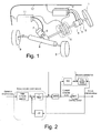
- FIG. 1 is a schematic view of a steer-by-wire (SBW) system of the vehicle steering control apparatus in accordance with the first embodiment.
- SBW steer-by-wire
- the SBW system of the first embodiment includes a steering wheel 1 (driver operating unit), a steering wheel angle sensor 2 (steering wheel angle detector), a torque sensor 3 (operating torque detector), a reaction force motor 4 (reaction force actuator), a clutch 5, a steering motor 6 (steering actuator), a steering motor angle sensor 7 (steering motor angle detector), a steering mechanism 8 (steering unit), left and right front wheels 9 (steered wheels), a reaction force controller 10, a steering controller 11 and a communication line 12.
- the controllers 10 and 11 include a microcomputer with control programs that controls various process of the steer-by-wire (SBW) system as discussed below.
- the controllers 10 and 11 can also include other conventional sections such as an input interface circuit, an output interface circuit, and storage devices such as a ROM (Read Only Memory) device and a RAM (Random Access Memory) device.
- ROM Read Only Memory
- RAM Random Access Memory
- the clutch engagement command issuing section issues an engagement command to the clutch 5.
- the clutch engagement determining section determines that the clutch 5 is in an engaged state when an increase in operating torque is detected at the steering wheel 1 (driver operating unit). More specifically, after the engagement command is issued to the clutch 5, the operating torque at the driver steering wheel 1 (driver operating unit) is substantially zero during the period in which the reaction force control has been aborted but the clutch 5 has not yet actually engaged.
- the clutch 5 When the clutch 5 actually engages, the torque from the road surface is transferred to the steering wheel 1 (driver operating unit) through the clutch 5 and the operating torque of the steering wheel 1 (driver operating unit) increases. Thus, it is possible to determine if the clutch 5 has engaged based on this relationship wherein the operating torque of the steering wheel 1 (driver operating unit) increases when the clutch engages.
- the time required for the clutch 5 to engage can vary depending on the operating state (e.g., the steering wheel operating angle or the steering wheel angular velocity) of the driver operating unit. By determining the endpoint of the clutch engagement process based on detection of torque transfer through the clutch 5, the actual engagement of the clutch 5 can be determined accurately regardless of variations in the clutch engagement time.
- the apparatus can shift smoothly to an electric power steering control mode or other steering wheel operation mode immediately after the clutch 5 actually engages.
- a vehicle steering control apparatus in accordance with the present invention can accurately determine when the clutch 5 has actually engaged regardless of variations in the clutch engagement time, and thus, can smoothly shift to a steering wheel operation mode immediately after the clutch 5 has actually engaged.
- the steering wheel 1 is arranged and configured to be operated by a driver.
- the steering mechanism 8 is arranged to be mechanically separated from the steering wheel 1 and configured to steer the left and right front wheels 9.
- the reaction force motor 4 is arranged and configured to impart an operation reaction force against the steering wheel 1.
- the steering motor 6 is arranged and configured to impart a drive force to the steering mechanism 8.
- the SBW system is configured such that there is no mechanical connection between the steering wheel 1 and the steering mechanism 8 during normal use with the clutch 5 in a disengaged state.
- the clutch 5 of the SBW system acts as a mechanical backup mechanism that enables the steering wheel 1 and the steering mechanism 8 to be connected together mechanically. In other words, when an abnormality (e.g., a malfunction) occurs in the SBW system, the clutch 5 is connected so that the vehicle can be driven safely.
- the steering wheel angle sensor 2 detects the rotary operation of the steering wheel 1, while the reaction force controller 10 calculates a command steering angle.
- the steering controller 11 calculates a drive command value for the steering motor 6 such that the actual steering angle is matched to the command steering angle.
- the vehicle is steered by driving the steering motor 6 based on the drive command value.
- the steering motor 6 is a brushless motor or another type of motor.
- the reaction force motor 4 is a brushless motor or the like for exerting the operation reaction force against the steering wheel.
- the reaction force motor 4 is driven based on a drive command value calculated by the reaction force controller 10.
- the drive command values calculated by the reaction force controller 10 and the steering controller 11 serve as current command values for the reaction force motor 4 and the steering motor 6.
- the reaction force motor 4 generates the operation reaction force of steering wheel 1 because the steering wheel 1 is not mechanically connected to the left and right wheels 9 and the steering motor 6.
- the operation reaction force is generated based on the axial force acting on a rack of the steering mechanism 8, the operating angle (rotational angle of the steering wheel), and the operating angular velocity (angular velocity at which the steering wheel is being turned).
- the torque sensor 3 is provided between the steering wheel 1 and the reaction force motor 4 and serves to enable the operating torque to be monitored.
- the torque sensor 3 is arranged and configured to detect the torsional strain or stress of the shaft and calculate the torque based on the torsional strain or stress.
- the value detected by the torque sensor 3 is not used during the SBW control but is used for control during the EPS mode (electric power steering mode) when a failure occurs in the reaction force motor 4 or the like.
- the clutch 5 is connected and the drive motor 6 is used in an assisting role.
- the value of the torque sensor 3 is monitored when a reaction force component failure or the like occurs.
- the reaction force component failure includes a failure occurring somewhere other than in the steering control system such as of the steering motor 6, the steering controller 11, and the steering angle sensor 7.
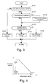
- the current command value calculated by the steering controller 11 is calculated with an angle servo system configured to control the actual (detected) steering angle such that it tracks the command steering angle with a prescribed response characteristic.
- the angle servo system of the steering controller 11 employs, for example a robust model matching method like that illustrated in the steering angle control block diagram of Figure 2.
- the robust model matching method includes a model matching compensator for matching to a predetermined characteristic and a robust compensator.
- the model matching compensator calculates a current command value for achieving the command steering angle with a prescribed response characteristic and the robust compensator calculates a compensating current for taking into account disturbance components.
- the actual (detected) steering angle can be made to follow the command steering angle with the prescribed response characteristic even when disturbances occur, i.e., the control system can be provided with an excellent resistance to disturbances.
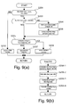
- FIG. 3 is a flowchart showing control processing executed by the reaction force controller 10 and the steering controller 11 of the first embodiment in order to switch the control mode when a reaction force component failure (e.g., reaction force failure) occurs.
- This processing sequence is executed by the controllers 10 and 11 once each time the SBW control cycle time elapses (e.g., every 5 msec).
- step S101 (first failure determining section) a determination is made as to whether a reaction force component failure (e.g., reaction force failure) has occurred, i.e., if an abnormality related to the reaction force control system exists, by executing a self-diagnosis of the reaction force controller 10 to see if a severed connection, short circuit, or other abnormality exists in the reaction force control system. If a failure has occurred (Yes), then control proceeds to step S103. If not (No), then control proceeds to step S102.
- a reaction force component failure e.g., reaction force failure
- reaction force controller 10 If a reaction force component failure (e.g., reaction force failure) is detected, the reaction force controller 10 aborts the reaction force control of the SBW control mode and communicates the occurrence of the reaction force component failure (e.g., reaction force failure) to the steering controller 11 through the communication line 12.
- reaction force component failure e.g., reaction force failure
- step S102 a normal SBW control mode is executed (a current command value is calculated for the reaction force motor 4 and a current command value is calculated for the steering motor 6).
- the controller returns to the beginning of the control sequence.
- step S103 a determination is made as to whether or not a clutch engagement command is being issued to the clutch 5. If so (Yes), then control proceeds to step S105. If not (No), then control proceeds to step S104.
- step S104 clutch engagement command issuing section
- a clutch engagement command is sent to the clutch 5 and then control proceeds to step S105.
- step S105 a determination is made as to whether or not the operating torque detected by the torque sensor 3 exceeds a preset prescribed value A (clutch engagement determination threshold value). If so (Yes), then control proceeds to step S107. If not (No), then control proceeds to step S 106.
- the prescribed value A is set to a value that will not result in an incorrect determination by taking into account the detection error of the torque sensor 3, the inertia of the steering wheel 1, and the inertia of the reaction force motor 4.
- the relative angular velocity is calculated based on a derivative of operating angle values detected by the steering wheel operating angle sensor 2 and a derivative of steering angle values detected by the steering angle sensor 7.
- step S106 (clutch engagement transitional steering control section) a steering holding control mode is executed which is contrived to calculate the command steering angle in such a manner as to hold the steered wheels 9 at the steering angle value that existed at the point in time when the engagement command was issued to the clutch 5. Then, control returns to the beginning of the control sequence.
- step S107 an EPS control mode is executed in which the steering motor 6 is used as an assisting force imparting section while the clutch 5 is in an engaged state. Then, control returns to the beginning of the control sequence.
- a current command value for steering assistance begins being calculated as the current command value for the steering motor 6 instead of the current command value used in the steering holding control mode.
- an abnormality occurs in the reaction force control system (e.g., failure of the reaction force motor 4)
- the clutch 5 is connected and the reaction force control executed by the reaction force controller 10 is aborted.
- the steering controller 11 calculates the current of the steering motor 6 based on the value detected by the torque sensor 3 such that the output of the steering motor 6 serves as a steering wheel operation assisting force, thereby accomplishing the function of an electric power steering device (EPS device).
- EPS device electric power steering device
- a comparative example will now be explained for a conventional apparatus in which the steering angle is held at the steering angle that existed when the engagement command was issued to the clutch during the period from when an abnormality of the reaction force actuator is first detected until a preset prescribed amount of time Ta elapses.
- the clutch engagement time and the preset prescribed amount of time Ta are assumed to match, the operating torque is held at a low value from the reaction force abnormality detection time T0 to the EPS control start time T2 and the operating torque characteristic rises from the EPS control start time T2.
- the driver's ability to operate the steering wheel is not inhibited.
- a vehicle steering control apparatus in accordance with the first embodiment can accurately determine when the clutch 5 has actually engaged regardless of variations in the clutch engagement time and, thus, can smoothly shift to a steering wheel operation mode immediately after the clutch 5 has actually engaged.
- the operating torque of the driver operating unit is set to substantially zero during the period when the reaction force control has been aborted but the clutch 5 is not yet connected.
- the clutch 5 actually engages the torque from the road surface is transferred to the driver operating unit through the clutch 5 and the operating torque of the driver operating unit increases.
- the first embodiment is contrived to utilize the fact that the operating torque of the driver operating unit rises when the clutch 5 engages.
- the engagement command is sent to the clutch 5 and, afterwards, a torque is transmitted from the road surface to the driver operating unit through the clutch 5.
- the apparatus determines that the clutch 5 is in an engaged state when it detects the increase in operating torque at the driver operating unit resulting from this torque transmission.
- the time required for the clutch 5 to engage can vary depending on the operating torque of the driver operating unit. By determining the endpoint of the clutch engagement process based on detection of torque transfer through the clutch, the actual (detected) engagement of the clutch 5 can be determined accurately regardless of variations in the clutch engagement time.
- the apparatus can shift smoothly to an EPS control mode or other steering wheel operation mode immediately after the clutch 5 actually engages.
- a vehicle steering control apparatus in accordance with the present invention can accurately determine when the clutch 5 has actually engaged regardless of variations in the clutch engagement time and, thus, can smoothly shift to a steering wheel operation mode immediately after the clutch 5 has actually engaged.
- step S101 When the reaction force control system is normal, the control processing flows from step S101 to step S102 of the flowchart shown in Figure 3.
- step S102 the reaction force control and steering control are executed in accordance with the normal SBW control mode with the clutch 5 disengaged.
- step S101 In the first control cycle after a failure occurs in the reaction force control system, control flows from step S101 to step S103 and then to step S104 of the flowchart shown in Figure 3.
- the reaction force control of the SBW control mode is aborted and in step S104 the clutch engagement command is issued to the clutch 5.
- step S106 the apparatus switches from executing steering control in SBW control mode to a steering holding control mode in which the steering angle is held at the steering angle that existed when the clutch engagement command was issued.
- step S105 So long as the clutch engagement determination condition of step S105 remains unsatisfied, the control processing repeats steps S101, S103, S105, and S106 (in order as listed) of the flowchart shown in Figure 3, thus continuing the steering holding control.
- step S107 the apparatus switches from the steering holding control mode to an EPS control mode in which the steering motor 6 is used as an assisting force imparting section.
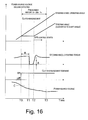
- Figure 7 illustrates the operation of the first embodiment in a situation where the driver is turning the steering wheel 1 and the clutch 5 engages in an amount of time shorter than the prescribed time Ta while the steering wheel operating angle is increasing.
- a reaction force abnormality is detected and the clutch engagement command is turned on.
- the command steering angle is also issued so as to hold the steering angle constant.
- the clutch 5 engages a force is transmitted from the road surface to the steering wheel 1 through the clutch 5 and the operating torque increases, as described previously.
- the operating torque is substantially zero because the reaction force control has been aborted.
- the apparatus determines that the clutch is engaged and switches from steering holding control mode to EPS control mode.
- the command steering angle is then changed from the held value to a value calculated based on the EPS control.
- the driver's operation of the steering wheel 1 is reflected in the steering angle and the operation reaction force is generated normally, enabling normal smooth steering wheel operation.
- the engagement of the clutch 5 can be determined based on the operating torque at the driver operating unit (steering wheel 1) without being affected by variations of the clutch engagement time.
- the problem of the previously described conventional technology i.e., the problem of the driver's ability to operate the steering wheel being inhibited, can be resolved.
- a torque sensor 3 is provided to detect the operating torque at the driver operating unit and the clutch engagement determining section (step S105) determines that the clutch 5 has entered an engaged state when, after the engagement command has been issued to the clutch 5, the operating torque detected by the torque sensor 3 exceeds a prescribed value A. If, for example, the clutch were determined to be engaged when the operating torque increased only slightly, then the clutch might be incorrectly determined to be engaged when the operating torque increased due to operation of the steering wheel by the driver. Conversely, if the clutch were determined to be engaged after the operating torque increased greatly, the determination timing would be late and the steering wheel reaction force would undergo a temporary increase after the engagement determination, causing the steering to feel unnatural to the driver.
- the prescribed value A serves as a threshold value for determining if the clutch 5 is engaged, i.e., the clutch 5 is determined to be engaged when the operating torque exceeds the prescribed value A.
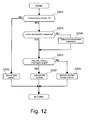
- the clutch engagement determining section sets the prescribed value A (clutch engagement determination threshold value) such that the faster the relative angular velocity is between the driver operating unit and the steering unit, the smaller the prescribed value A becomes.
- the timing at which engagement of the clutch 5 is completed can be determined accurately regardless of whether the relative angular velocity across the clutch 5 is fast or slow when a clutch employing a meshing structure is used.
- a vehicle steering control apparatus in accordance with the first embodiment is provided with a reaction force motor 4 configured to impart an operation reaction force to the driver operating unit and a steering motor 6 configured to impart a steering force to the steering unit.
- the clutch engagement determining section determines that the clutch 5 is engaged
- the apparatus switches from the SBW control mode involving reaction force control and steering control that was being executed before the engagement command was issued to the clutch 5 to an EPS control mode (step S107) in which at least one of the reaction force motor 4 and the steering motor 6 is used as an assisting force imparting section.
- the apparatus were configured to simply switch from the SBW control mode to a direct steering mode in which the steering wheel is connected directly to the steering mechanism when the clutch becomes engaged, the steering load born by the driver would be excessively large in cases where a large steering wheel operation reaction force was transmitted from the road surface, such as when the steering wheel is turned in one direction and held.
- the apparatus since the apparatus switches to an EPS control mode when it determines that the clutch 5 is engaged, the steering load born by the driver is low immediately after the clutch 5 actually engages. More specifically, the steering load is low because the EPS control mode assists the driver with respect to operating the steering wheel 1.
- a vehicle steering control apparatus in accordance with the first embodiment is provided with a first failure determining section (step S101) configured to determine if a reaction force component failure (e.g., reaction force failure) has occurred and a clutch engagement command issuing section (step S104) configured to issue an engagement command to the clutch based on a determination that a failure has occurred somewhere related to the reaction force.
- the apparatus is further provided with a clutch engagement transitional steering control section (step S106) configured to switch from steering control in the SBW control mode to a vehicle behavior suppressing steering control during the period from when the clutch engagement command issuing section issues the engagement command until the clutch engagement determining section (step S105) determines that the clutch 5 is in an engaged state.
- the apparatus were configured such that the SBW control was continued until the clutch engaged after a reaction force component failure (e.g., reaction force failure) occurred, it would be more likely for the steering wheel operating amount or angle to change greatly in opposition to the intent of the driver because a reaction torque would not be generated. In such a case, the vehicle behavior would become unstable because the SBW control would change the steering angle in accordance with the steering wheel operating amount.
- a reaction force component failure e.g., reaction force failure
- the steering control of the SBW control mode is switched to a vehicle behavior suppressing steering control during the period from when the engagement command is issued until the clutch 5 is determined to be engaged.
- the clutch engagement transitional steering control section (step S106) is configured to switch to a steering holding control contrived to maintain the steering angle that existed at the point in time when the clutch engagement command issuing section (step S104) issued the engagement command to the clutch 5.
- a vehicle steering control apparatus in accordance with the first embodiment achieves the effects listed below.
- the prescribed amount of time B for stopping the reaction force control is set such that the faster the relative angular velocity between the driver operating unit and the steering unit is, the shorter the value of the time B becomes.
- the clutch engagement determining section determines that the clutch 5 has entered an engaged state when the operating torque detected by the torque sensor 3 exceeds a prescribed value A (clutch engagement determination threshold value).
- a prescribed value A clutch engagement determination threshold value
- Steps S401 to S404 and steps S406 and S407 are the same as steps S101 to S104 and steps S106 and S107, respectively, of the flowchart shown in Figure 3 and explanations there of are omitted for the sake of brevity.
- any section of determining that the clutch is engaged when an increase in operating torque is detected at the driver operating unit after the engagement command is issued to the clutch is included within the scope of the present invention.
- the present invention can also be applied to SBW systems having, for example, a clutch and a backup cable.
- the present invention can be applied to any vehicle steering control apparatus in which a driver operating unit and a steering unit are separated by releasing a clutch and a steer-by-wire control is executed which is contrived to issue a control command that drives a steering actuator such that a steering angle corresponding to the operating torque of the driver operating unit is achieved by the steering unit and a control command that drives a reaction force actuator such that an operation reaction force corresponding to the steering state of the steering unit is imparted to the driver operating unit.
- detect as used herein to describe an operation or function carried out by a component, a section, a device or the like includes a component, a section, a device or the like that does not require physical detection, but rather includes determining, measuring, modeling, predicting or computing or the like to carry out the operation or function.
- Configured as used herein to describe a component, section or part of a device includes hardware and/or software that is constructed and/or programmed to carry out the desired function.
- terms that are expressed as “means-plus function” in the claims should include any structure that can be utilized to carry out the function of that part of the present invention.
- degree such as “substantially”, “about” and “approximately” as used herein mean a reasonable amount of deviation of the modified term such that the end result is not significantly changed.
Landscapes
- Engineering & Computer Science (AREA)
- Chemical & Material Sciences (AREA)
- Combustion & Propulsion (AREA)
- Transportation (AREA)
- Mechanical Engineering (AREA)
- Power Steering Mechanism (AREA)
- Steering Control In Accordance With Driving Conditions (AREA)
- Arrangement And Driving Of Transmission Devices (AREA)
Applications Claiming Priority (1)
| Application Number | Priority Date | Filing Date | Title |
|---|---|---|---|
| JP2006057271A JP4853053B2 (ja) | 2006-03-03 | 2006-03-03 | 車両用操舵制御装置 |
Publications (3)
| Publication Number | Publication Date |
|---|---|
| EP1829765A2 true EP1829765A2 (de) | 2007-09-05 |
| EP1829765A3 EP1829765A3 (de) | 2007-11-07 |
| EP1829765B1 EP1829765B1 (de) | 2009-09-16 |
Family
ID=38093481
Family Applications (1)
| Application Number | Title | Priority Date | Filing Date |
|---|---|---|---|
| EP07103281A Active EP1829765B1 (de) | 2006-03-03 | 2007-03-01 | Fahrzeuglenkung |
Country Status (5)
| Country | Link |
|---|---|
| US (1) | US7690475B2 (de) |
| EP (1) | EP1829765B1 (de) |
| JP (1) | JP4853053B2 (de) |
| CN (1) | CN101028832B (de) |
| DE (1) | DE602007002422D1 (de) |
Cited By (3)
| Publication number | Priority date | Publication date | Assignee | Title |
|---|---|---|---|---|
| WO2014203056A1 (en) * | 2013-06-19 | 2014-12-24 | Toyota Jidosha Kabushiki Kaisha | Steering system for vehicle |
| EP3098139A1 (de) * | 2015-05-29 | 2016-11-30 | Jtekt Corporation | Lenkvorrichtung |
| EP3398831A1 (de) * | 2017-05-01 | 2018-11-07 | Jtekt Corporation | Lenksteuerungsvorrichtung |
Families Citing this family (30)
| Publication number | Priority date | Publication date | Assignee | Title |
|---|---|---|---|---|
| JP4876634B2 (ja) * | 2006-03-01 | 2012-02-15 | 日産自動車株式会社 | 車両用操舵制御装置 |
| US7810605B2 (en) * | 2006-12-28 | 2010-10-12 | Nissan Motor Co., Ltd. | Vehicle steering device and control method for vehicle steering device |
| WO2008086248A2 (en) | 2007-01-06 | 2008-07-17 | Magcanica, Inc. | Devices and methods for detecting rates of change of torque |
| EP2383167B1 (de) * | 2010-04-27 | 2013-12-04 | ThyssenKrupp Presta AG | Verfahren zur Steuerung einer Lenkvorrichtung |
| JP5816019B2 (ja) * | 2011-07-29 | 2015-11-17 | Ntn株式会社 | 冗長機能付きステアバイワイヤ式操舵装置の制御装置 |
| US9096254B2 (en) | 2012-01-31 | 2015-08-04 | Toyota Jidosha Kabushiki Kaisha | Vehicle steering control apparatus |
| JP5673630B2 (ja) * | 2012-09-04 | 2015-02-18 | トヨタ自動車株式会社 | 操舵装置 |
| JP5930058B2 (ja) * | 2012-10-03 | 2016-06-08 | 日産自動車株式会社 | ステアリング制御装置、ステアリング制御方法 |
| CN103072621B (zh) * | 2013-02-05 | 2016-01-13 | 奇瑞汽车股份有限公司 | 电动助力转向系统 |
| EP2985207B1 (de) * | 2013-04-08 | 2018-05-23 | Mitsubishi Electric Corporation | Lenksteuerungsvorrichtung und lenksteuerungsverfahren |
| US9139223B2 (en) * | 2013-05-23 | 2015-09-22 | Caterpillar Inc. | Managing steering with short from battery to ground |
| JP6101219B2 (ja) * | 2014-01-21 | 2017-03-22 | 本田技研工業株式会社 | 車両用操舵システム |
| JP6131199B2 (ja) * | 2014-01-21 | 2017-05-17 | 本田技研工業株式会社 | 車両用操舵装置 |
| JP2016055678A (ja) * | 2014-09-05 | 2016-04-21 | 株式会社ジェイテクト | ステアリング装置及び電動パワーステアリング装置 |
| JP2016132264A (ja) * | 2015-01-15 | 2016-07-25 | 株式会社ジェイテクト | 車両用操舵装置 |
| CN106184352A (zh) * | 2016-07-13 | 2016-12-07 | 吉林大学 | 一种可实现多种转向模式切换的转向系统 |
| US9975573B2 (en) | 2016-07-29 | 2018-05-22 | Ford Global Technologies, Llc | Enhanced steering operation |
| JP6711196B2 (ja) * | 2016-08-02 | 2020-06-17 | いすゞ自動車株式会社 | 操舵補助装置及び操舵補助方法 |
| US10358162B2 (en) * | 2016-10-03 | 2019-07-23 | Jtekt Corporation | Steering control device |
| JP6533772B2 (ja) * | 2016-11-29 | 2019-06-19 | 本田技研工業株式会社 | 操舵装置 |
| US10427711B2 (en) * | 2017-07-18 | 2019-10-01 | GM Global Technology Operations LLC | Method of self-diagnosis for power steering assembly |
| DE102018200094B4 (de) | 2018-01-04 | 2021-09-02 | Robert Bosch Gmbh | Verfahren und Vorrichtung zum Betreiben eines Lenksystems für ein Kraftfahrzeug, Lenksystem |
| CN108387342A (zh) * | 2018-01-08 | 2018-08-10 | 联创汽车电子有限公司 | Eps非接触式扭矩传感器故障识别系统及其识别方法 |
| JP6988579B2 (ja) * | 2018-03-05 | 2022-01-05 | いすゞ自動車株式会社 | 制御装置及び制御方法 |
| DE102018218588A1 (de) * | 2018-10-30 | 2020-04-30 | Audi Ag | Verfahren zum Betreiben eines Kraftfahrzeugs sowie entsprechendes Kraftfahrzeug |
| CN110667700B (zh) * | 2019-11-19 | 2020-11-13 | 清华大学 | 车辆转向模式切换方法、装置及电子设备 |
| CN115298079A (zh) * | 2020-03-17 | 2022-11-04 | 日立安斯泰莫株式会社 | 转向控制装置 |
| JP7200210B2 (ja) * | 2020-12-25 | 2023-01-06 | 本田技研工業株式会社 | 移動体 |
| FR3125003B1 (fr) * | 2021-07-08 | 2024-08-30 | Jtekt Europe Sas | Procede de determination de couple de frottements |
| CN116279771B (zh) * | 2023-04-26 | 2024-03-26 | 东莞市卓越电动车有限公司 | 自助力转向的方向机 |
Citations (2)
| Publication number | Priority date | Publication date | Assignee | Title |
|---|---|---|---|---|
| EP0983926A2 (de) | 1998-09-02 | 2000-03-08 | DaimlerChrysler AG | Lenksystem für nicht spurgebundene Kraftfahrzeuge |
| JP2005096745A (ja) | 2003-08-28 | 2005-04-14 | Nissan Motor Co Ltd | 車両用操舵装置 |
Family Cites Families (16)
| Publication number | Priority date | Publication date | Assignee | Title |
|---|---|---|---|---|
| JPH02124363A (ja) * | 1988-10-31 | 1990-05-11 | Mazda Motor Corp | 電動式パワーステアリング装置 |
| JP3447087B2 (ja) * | 1993-09-08 | 2003-09-16 | カヤバ工業株式会社 | 電動パワーステアリング制御装置 |
| JP3184855B2 (ja) * | 1994-03-31 | 2001-07-09 | スズキ株式会社 | 電動パワーステアリング装置 |
| JP2004351975A (ja) * | 2003-05-27 | 2004-12-16 | Ntn Corp | ステアバイワイヤシステムのフェールセーフ機構およびステアバイワイヤシステム |
| DE602004025068D1 (de) * | 2003-06-11 | 2010-03-04 | Nissan Motor | Ausfallsichere Lenkanlage für ein Kraftfahrzeug |
| US7004279B2 (en) * | 2003-08-28 | 2006-02-28 | Nissan Motor Co., Ltd. | Vehicle steering system |
| CN2645999Y (zh) * | 2003-09-09 | 2004-10-06 | 重庆驰骋轻型汽车部件股份有限公司 | 汽车电动助力转向器 |
| US6926112B2 (en) * | 2003-10-16 | 2005-08-09 | Visteon Global Technologies, Inc. | End of travel system and method for steer by wire systems |
| US7174987B2 (en) * | 2003-10-16 | 2007-02-13 | Visteon Global Technologies, Inc. | End of travel feature for steer by wire vehicle |
| US6929086B1 (en) * | 2004-02-18 | 2005-08-16 | Visteon Global Technologies, Inc. | Motor vehicle steering system |
| JP4604566B2 (ja) * | 2004-06-17 | 2011-01-05 | 日産自動車株式会社 | 車両用操舵装置 |
| JP4682639B2 (ja) * | 2005-02-15 | 2011-05-11 | 日産自動車株式会社 | 操舵制御装置 |
| JP4792815B2 (ja) * | 2005-05-27 | 2011-10-12 | 日産自動車株式会社 | 車両用操舵装置 |
| JP4640290B2 (ja) | 2005-11-21 | 2011-03-02 | 日産自動車株式会社 | ワーク移し替えのための方法及びシステム |
| JP4984504B2 (ja) | 2005-11-29 | 2012-07-25 | 日産自動車株式会社 | 車両用操舵制御装置 |
| JP5028795B2 (ja) * | 2005-12-09 | 2012-09-19 | 日産自動車株式会社 | 車両用操舵制御装置 |
-
2006
- 2006-03-03 JP JP2006057271A patent/JP4853053B2/ja not_active Expired - Lifetime
-
2007
- 2007-02-20 US US11/707,941 patent/US7690475B2/en active Active
- 2007-03-01 EP EP07103281A patent/EP1829765B1/de active Active
- 2007-03-01 DE DE602007002422T patent/DE602007002422D1/de active Active
- 2007-03-02 CN CN2007100803537A patent/CN101028832B/zh active Active
Patent Citations (2)
| Publication number | Priority date | Publication date | Assignee | Title |
|---|---|---|---|---|
| EP0983926A2 (de) | 1998-09-02 | 2000-03-08 | DaimlerChrysler AG | Lenksystem für nicht spurgebundene Kraftfahrzeuge |
| JP2005096745A (ja) | 2003-08-28 | 2005-04-14 | Nissan Motor Co Ltd | 車両用操舵装置 |
Cited By (6)
| Publication number | Priority date | Publication date | Assignee | Title |
|---|---|---|---|---|
| WO2014203056A1 (en) * | 2013-06-19 | 2014-12-24 | Toyota Jidosha Kabushiki Kaisha | Steering system for vehicle |
| US9751555B2 (en) | 2013-06-19 | 2017-09-05 | Toyota Jidosha Kabushiki Kaisha | Steering system for vehicle |
| EP3098139A1 (de) * | 2015-05-29 | 2016-11-30 | Jtekt Corporation | Lenkvorrichtung |
| CN106184349A (zh) * | 2015-05-29 | 2016-12-07 | 株式会社捷太格特 | 转向操纵装置 |
| US9988072B2 (en) | 2015-05-29 | 2018-06-05 | Jtekt Corporation | Steering apparatus |
| EP3398831A1 (de) * | 2017-05-01 | 2018-11-07 | Jtekt Corporation | Lenksteuerungsvorrichtung |
Also Published As
| Publication number | Publication date |
|---|---|
| US7690475B2 (en) | 2010-04-06 |
| EP1829765A3 (de) | 2007-11-07 |
| JP2007230472A (ja) | 2007-09-13 |
| CN101028832A (zh) | 2007-09-05 |
| CN101028832B (zh) | 2010-06-02 |
| DE602007002422D1 (de) | 2009-10-29 |
| EP1829765B1 (de) | 2009-09-16 |
| US20070215405A1 (en) | 2007-09-20 |
| JP4853053B2 (ja) | 2012-01-11 |
Similar Documents
| Publication | Publication Date | Title |
|---|---|---|
| EP1829765B1 (de) | Fahrzeuglenkung | |
| EP1829766B1 (de) | Fahrzeuglenkbetätigung | |
| JP7473717B2 (ja) | 操舵角を決定するための方法および制御装置 | |
| EP1939069B1 (de) | Fahrzeuglenkvorrichtung und Steuerungsverfahren für eine Fahrzeuglenkvorrichtung | |
| US7664584B2 (en) | Steering control system | |
| EP1510436B1 (de) | Fahrzeuglenksystem | |
| EP2383167B1 (de) | Verfahren zur Steuerung einer Lenkvorrichtung | |
| EP2851267B1 (de) | Fahrzeuglenksteuerungsvorrichtung und lenksteuerungsverfahren | |
| JP5206845B2 (ja) | 車両用操舵制御装置 | |
| EP1795429B1 (de) | Fahrzeuglenkung | |
| JP7498269B2 (ja) | 車両の操舵装置 | |
| JPWO1998033270A1 (ja) | 電動パワーステアリング制御装置 | |
| JP5298478B2 (ja) | 電動パワーステアリング装置 | |
| JP4506509B2 (ja) | 操舵制御装置 | |
| JP5332213B2 (ja) | ステアバイワイヤシステムの診断装置およびステアバイワイヤシステムの診断方法 | |
| JP4517902B2 (ja) | 操舵制御装置 | |
| JP4449488B2 (ja) | 電動パワーステアリング装置の制御装置 | |
| JP2013241131A (ja) | 車両用舵角検出装置及び電動パワーステアリング装置 | |
| JP5817936B2 (ja) | 車両用操舵制御装置 | |
| JP2005206070A (ja) | 電動パワーステアリング装置の制御装置 | |
| JP2005231416A (ja) | 車両操舵装置 | |
| JP2025007667A (ja) | 車両用手放し状態判定装置 |
Legal Events
| Date | Code | Title | Description |
|---|---|---|---|
| PUAI | Public reference made under article 153(3) epc to a published international application that has entered the european phase |
Free format text: ORIGINAL CODE: 0009012 |
|
| AK | Designated contracting states |
Kind code of ref document: A2 Designated state(s): AT BE BG CH CY CZ DE DK EE ES FI FR GB GR HU IE IS IT LI LT LU LV MC MT NL PL PT RO SE SI SK TR |
|
| AX | Request for extension of the european patent |
Extension state: AL BA HR MK YU |
|
| PUAL | Search report despatched |
Free format text: ORIGINAL CODE: 0009013 |
|
| AK | Designated contracting states |
Kind code of ref document: A3 Designated state(s): AT BE BG CH CY CZ DE DK EE ES FI FR GB GR HU IE IS IT LI LT LU LV MC MT NL PL PT RO SE SI SK TR |
|
| AX | Request for extension of the european patent |
Extension state: AL BA HR MK YU |
|
| 17P | Request for examination filed |
Effective date: 20080507 |
|
| 17Q | First examination report despatched |
Effective date: 20080613 |
|
| AKX | Designation fees paid |
Designated state(s): DE FR GB |
|
| GRAP | Despatch of communication of intention to grant a patent |
Free format text: ORIGINAL CODE: EPIDOSNIGR1 |
|
| GRAS | Grant fee paid |
Free format text: ORIGINAL CODE: EPIDOSNIGR3 |
|
| GRAA | (expected) grant |
Free format text: ORIGINAL CODE: 0009210 |
|
| AK | Designated contracting states |
Kind code of ref document: B1 Designated state(s): DE FR GB |
|
| REG | Reference to a national code |
Ref country code: GB Ref legal event code: FG4D |
|
| REF | Corresponds to: |
Ref document number: 602007002422 Country of ref document: DE Date of ref document: 20091029 Kind code of ref document: P |
|
| PLBE | No opposition filed within time limit |
Free format text: ORIGINAL CODE: 0009261 |
|
| STAA | Information on the status of an ep patent application or granted ep patent |
Free format text: STATUS: NO OPPOSITION FILED WITHIN TIME LIMIT |
|
| 26N | No opposition filed |
Effective date: 20100617 |
|
| REG | Reference to a national code |
Ref country code: FR Ref legal event code: PLFP Year of fee payment: 10 |
|
| REG | Reference to a national code |
Ref country code: FR Ref legal event code: PLFP Year of fee payment: 11 |
|
| REG | Reference to a national code |
Ref country code: FR Ref legal event code: PLFP Year of fee payment: 12 |
|
| REG | Reference to a national code |
Ref country code: DE Ref legal event code: R084 Ref document number: 602007002422 Country of ref document: DE |
|
| REG | Reference to a national code |
Ref country code: GB Ref legal event code: 746 Effective date: 20230925 |
|
| PGFP | Annual fee paid to national office [announced via postgrant information from national office to epo] |
Ref country code: DE Payment date: 20250218 Year of fee payment: 19 |
|
| PGFP | Annual fee paid to national office [announced via postgrant information from national office to epo] |
Ref country code: FR Payment date: 20250218 Year of fee payment: 19 |
|
| PGFP | Annual fee paid to national office [announced via postgrant information from national office to epo] |
Ref country code: GB Payment date: 20250221 Year of fee payment: 19 |