EP1829767A2 - Cadre auxiliaire pour monter à la carrosserie d'un véhicule automobile - Google Patents
Cadre auxiliaire pour monter à la carrosserie d'un véhicule automobile Download PDFInfo
- Publication number
- EP1829767A2 EP1829767A2 EP07003992A EP07003992A EP1829767A2 EP 1829767 A2 EP1829767 A2 EP 1829767A2 EP 07003992 A EP07003992 A EP 07003992A EP 07003992 A EP07003992 A EP 07003992A EP 1829767 A2 EP1829767 A2 EP 1829767A2
- Authority
- EP
- European Patent Office
- Prior art keywords
- subframe according
- cross member
- subframe
- rear metal
- stiffening
- Prior art date
- Legal status (The legal status is an assumption and is not a legal conclusion. Google has not performed a legal analysis and makes no representation as to the accuracy of the status listed.)
- Granted
Links
Images

Classifications
-
- B—PERFORMING OPERATIONS; TRANSPORTING
- B62—LAND VEHICLES FOR TRAVELLING OTHERWISE THAN ON RAILS
- B62D—MOTOR VEHICLES; TRAILERS
- B62D21/00—Understructures, i.e. chassis frame on which a vehicle body may be mounted
- B62D21/15—Understructures, i.e. chassis frame on which a vehicle body may be mounted having impact absorbing means, e.g. a frame designed to permanently or temporarily change shape or dimension upon impact with another body
- B62D21/152—Front or rear frames
- B62D21/155—Sub-frames or underguards
-
- B—PERFORMING OPERATIONS; TRANSPORTING
- B62—LAND VEHICLES FOR TRAVELLING OTHERWISE THAN ON RAILS
- B62D—MOTOR VEHICLES; TRAILERS
- B62D21/00—Understructures, i.e. chassis frame on which a vehicle body may be mounted
- B62D21/11—Understructures, i.e. chassis frame on which a vehicle body may be mounted with resilient means for suspension, e.g. of wheels or engine; sub-frames for mounting engine or suspensions
Definitions
- the invention relates to a subframe for attachment to a body of a motor vehicle specified in the preamble of claim 1.
- Such subframes are generally referred to in motor vehicle construction as axle carrier, axle stanchion or integral carrier and are used both in the area of the front end structure and in the region of the rear structure of motor vehicles.
- such subframes are often provided with receptacles for the steering gear, for stabilizers, for the drive unit, for a differential gear or the like in addition to the stiffening of the stem or tail structure such subframe also for connection and support of Rad Operationssgliedern or axle links.
- Such a subframe is for example from the EP 0 941 912 B1 to be known, in which two extending in the vehicle longitudinal direction and spaced-apart longitudinal carrier elements are provided in sheet metal shell construction, soft at their the Kraftwagenbug facing front ends are connected via a transverse direction transverse to the vehicle transverse member to a U-shaped frame.
- the composite of the two lateral side member elements and the cross member element is stiffened by a planar stiffening element in the form of a stiffening plate.
- the stiffening element is fastened via respective three screws to associated brackets of the respective side member.
- a disadvantage of the known subframe is the fact that this is relatively difficult to the deformation behavior of the stem or Rear structure of the motor vehicle can be adjusted.
- the attachment points for fixing the subframe to the motor vehicle body as well as receptacles for mounting the wheel guide or axle guide are arranged in a relatively complicated manner on the subframe.
- Object of the present invention is therefore to provide a subframe of the type mentioned, the simpler structure, better adapt to the grass behavior of the associated stem or tail structure and beyond is particularly stiff form.
- the longitudinal beam elements each comprise a longitudinal support part arranged between a front and rear metal casting, designed as an energy absorbing deformation part, wherein the stiffening element is connected at least on one side to the cross member and on the other hand to the rear metal castings. Due to the design of the longitudinal beam elements, each with a front and rear metal casting, it is possible to attach attachment points for fixing the subframe to the Kraftvuagenkarosserie or shots for holding Fahrtechniksgliedem or Achslenkern in a simple way directly to the respective Iv1etaligussteil.
- the embodiment according to the invention of the longitudinal beam elements with the energy-absorbing longitudinal beam part arranged between the two respective Ntetailguss maximise allows a precise tuning of the subframe on the deformation capacity or the deformation property the associated stem or tail structure.
- the stiffening element provided according to the invention enables stiffening of the cross member element and an extremely stable connection of the rear metal cast parts with the cross member element, so that in the event of a crash-induced loading of the subframe the accident forces acting on the cross member element can be very well absorbed.
- the stiffening element in a further embodiment of the invention, it has also proven to be advantageous to form the stiffening element as a flat stiffening plate, which extends between the front and rear metal castings.
- a flat stiffening plate is very easy and inexpensive to produce and allows a high degree of freedom in the choice of attachment points of the stiffening plate on the side rail members or on the least one cross member.
- a stiffening element designed as a crossbar has proven to be particularly advantageous, whose struts extend between the respective front and the laterally opposite rear metal casting.
- a cross brace is characterized in particular by the fact that it can be formed particularly well-weighted and the subframe particularly good stiffening.
- the front metal cast parts each have a receptacle for fixing the cross member, wherein the stiffening element is connected in the region of the receptacles with the cross member.
- the stiffening element is connected in the region of the receptacles with the cross member.
- a particularly rigid connection of the stiffening element to the longitudinal support elements of the subframe can also be realized if the front metal cast parts each comprise a further receptacle for fastening the stiffening element. These further receptacles are preferably arranged - viewed in the vehicle longitudinal direction - at a distance behind the receptacles for the cross member.
- the subframe can be further stiffened by the fact that the two ends of the side rail members are also connected to one another on the side facing away from the front cross member element with another cross member. As a result, this results in a substantially rectangular closed frame, which is particularly easy to stiffen by the stiffening element.
- the rear cross member can also be formed integrally with the stiffening element.
- the rear metal cast parts each comprise a receptacle for fastening the associated energy-absorbing deformation part, wherein a particularly rigid composite can be realized incorporating the rear metal castings by the stiffening element is fixed in the recordings with the rear metal castings.
- the front and rear metal castings provided with connection points for Rad Operationssglieder of the chassis of the motor vehicle, then the connection of the chassis to the subframe is to realize a simple manufacturing technology.
- the subframe is formed in the present embodiment as an axle, which is to be fastened to the underside of a front structure of the motor vehicle body and is used in more detail below for receiving or supporting suspension members or Achslenkem.
- the subframe can of course also be attached to the car floor of a rear structure of the motor vehicle.
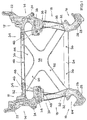
- the subframe essentially comprises two longitudinal carrier elements 10, 12 extending in the vehicle longitudinal direction and spaced from each other, of which the left longitudinal carrier element 10 in FIG. 2 can be seen in more detail in a schematic side view.
- Each of the longitudinal support elements 10, 12 essentially comprises a front metal casting 14 and a rear metal casting 16, which are connected to one another via a longitudinal support member 18 formed as an energy absorbing deformation member.
- the front and rear metal castings 14, 16 made of achtmetallitegtechnik, for example Aluminum or magnesium base, manufactured.
- other casting alloys customary in motor vehicle construction would also be conceivable.
- the front metal cast parts 14 each comprise two fastening points 22, 24, via which the longitudinal support elements 10, 12 are to be fastened at their respective front side in a manner not shown on the underside by longitudinal members running in the region of the carriage bottom of the motor vehicle body.
- the rear metal cast parts 16 each comprise two attachment points 26, 28, via which the two side rail elements 10, 12 are to be fastened at their rear ends to the longitudinal members running at the level of the carriage bottom of the motor vehicle body.
- the longitudinal carrier parts 18 can be designed, for example, as a one-chamber or multi-chamber profile produced by means of extrusion.
- the extruded profile can be converted by means of a hydroforming process (IHU) for the purpose of further cross-sectional design and / or calibration.
- the shaping of the longitudinal member part 18 may also include a bending and / or embossing process. It is clear that the hollow profile of the longitudinal carrier element 18 designed as an energy-absorbing deformation adjustment can also be produced in another conventional manner. It is essential, however, that the respective longitudinal support member 18 has a high energy absorption capacity and can reduce energy without the formation of force peaks.
- the front and the rear metal casting 14, 16 each comprise a receptacle 30, 32, to which the longitudinal support member 18 can be attached.
- the receptacles 30, 32 of the respective two metal cast parts 14, 16 can be designed as plug connection elements which are inserted at the associated end into the hollow profile of the respective longitudinal carrier part 18.
- the two metal castings 14, 16 can be fixed in the region of the receptacles 30, 32 via a respective joining or screw connection.
- the front metal cast parts 14 in each case comprise a receptacle 34 projecting toward the opposite side rail element 10, 12 or to the vehicle center, via which the two side rail elements 10, 12 are connected to a crossbeam element 36.
- the recordings 34 can thereby in turn be designed as a plug connection elements on which the cross member formed as a hollow profile member 36 can be plugged.
- the cross member 36 may be connected by means of a joint or screw or the like with the two front metal castings 14.
- the front cross member 36 is preferably formed as an extruded profile with a hollow cross-section. Likewise, of course, other configurations of the cross member element 36 would be conceivable.
- the front metal cast parts 14 each include a support arm 38 projecting toward the opposite side rail element 10, 12 or towards the vehicle center, on whose rear side a respective receptacle 40 is formed.
- a stiffening element 42 can be fixed, of which in FIG. 1 essentially two embodiments can be seen.
- the stiffening element 42 is formed as a flat stiffening plate 44, for example, of a metal sheet which extends between the front and rear metal castings 14, 16.
- the stiffening plate 44 is designed substantially trapezoidal, wherein this is narrower on the side facing the Kraftwagenbug front than on the rear side facing away therefrom.
- the stiffening plate 44 is fixed to the front Quesnovaelement 36.
- the stiffening element 42 or the stiffening plate 44 is connected to the two rear metal cast parts 16.
- an attachment point 50 is provided in the overlap region between the metallgußü spa spas 32 and the associated end of the L jossskaiefifs 18.
- the stiffening plate 44 in the present exemplary embodiment is screwed releasably to the two longitudinal support elements 10, 12 or the transverse support element 36 by means of screw connections (not shown).
- the stiffening element 42 and the stiffening plate 44 in other common manner detachable or insoluble with the side member elements 10, 12 and the cross member 36 to connect.
- the stiffening element 42 or the stiffening plate 44 is only indirectly connected to the respective associated rear metal castings 16, for example by the attachment points 50 are not provided directly to the receptacles 32 of the respective rear metal casting 16, but in the vicinity, For example, in the region of the respective longitudinal support member 18.
- the stiffening element 42 may be attached only to the attachment points 48 in a central region of the cross member 36 on the one hand and on the rear metal castings 16 on the other hand.
- stiffening plate 44 - as indicated by the dashed line 52 - tapering towards the front starting from receptacles 40 and essentially comes to rest only in the region of the cross member 36, in which this extends within the two receptacles 34.
- the rear metal casting parts 16 are connected to one another via a rear cross member element 54, which in the present exemplary embodiment is designed integrally with the reinforcing plate 44.
- a rear cross member element 54 which in the present exemplary embodiment is designed integrally with the reinforcing plate 44.
- the stiffening plate 44 can be connected to the cross member element 54 in the region of the attachment points 56.
- the rear cross member is connected in the region of the receptacles 32 with the rear metal castings 16.
- a stiffening element 42 in the form of a cross strut 58 is indicated by dashed lines in Fig. 1.
- the crossbar 58 essentially comprises two struts 60, 62, which extend between the respective front and the laterally opposite rear metal casting 14, 16.
- the struts 60, 62 of the cross strut 58 are screwed in the region of the attachment points 46, 50 with the receptacles 34 of the front metal casting 14 and the receptacles 32 of the rear metal casting 16.
- the rear cross member 54 may be formed as a separate part and also be fixed to the receptacles 32 of the rear metal casting 16.
- the two struts 60, 62 of the cross brace 58 are welded in a central region and reinforced accordingly.
- the struts 60, 62 are preferably formed as hollow profiles, and in particular as extruded profiles.
- the front and rear metal castings 14, 16 include for fixing Rad operationsgliedern or Achslankern of the chassis of the motor vehicle a plurality of attachment points, of which, for example, a substantially U-shaped Anbiridungsstelle 64 of the rear metal casting 16 can be seen.
- stiffening element 42 designed as a stiffening plate 44 or a crossbar 58 extends on the underside of the side rail elements 10, 12 or of the cross member element 36.
Landscapes
- Engineering & Computer Science (AREA)
- Chemical & Material Sciences (AREA)
- Combustion & Propulsion (AREA)
- Transportation (AREA)
- Mechanical Engineering (AREA)
- Body Structure For Vehicles (AREA)
Applications Claiming Priority (1)
| Application Number | Priority Date | Filing Date | Title |
|---|---|---|---|
| DE200610009289 DE102006009289A1 (de) | 2006-03-01 | 2006-03-01 | Hilfsrahmen zur Befestigung an einer Karosserie eines Kraftwagens |
Publications (3)
| Publication Number | Publication Date |
|---|---|
| EP1829767A2 true EP1829767A2 (fr) | 2007-09-05 |
| EP1829767A3 EP1829767A3 (fr) | 2008-03-26 |
| EP1829767B1 EP1829767B1 (fr) | 2009-08-19 |
Family
ID=37897749
Family Applications (1)
| Application Number | Title | Priority Date | Filing Date |
|---|---|---|---|
| EP20070003992 Active EP1829767B1 (fr) | 2006-03-01 | 2007-02-27 | Cadre auxiliaire pour monter à la carrosserie d'un véhicule automobile |
Country Status (3)
| Country | Link |
|---|---|
| EP (1) | EP1829767B1 (fr) |
| DE (2) | DE102006009289A1 (fr) |
| ES (1) | ES2330891T3 (fr) |
Cited By (6)
| Publication number | Priority date | Publication date | Assignee | Title |
|---|---|---|---|---|
| EP1837268A3 (fr) * | 2006-03-24 | 2008-05-14 | Audi Ag | Châssis auxiliaire pour véhicules automobiles et procédé de montage d'un groupe motopropulseur sur un tel châssis auxiliaire |
| WO2010048917A1 (fr) * | 2008-10-30 | 2010-05-06 | Ksm Castings Gmbh | Support d'essieu avant pour un véhicule à moteur ainsi que son procédé de fabrication |
| WO2014005786A1 (fr) * | 2012-07-03 | 2014-01-09 | Zf Friedrichshafen Ag | Véhicule automobile muni d'un châssis de véhicule |
| EP2457807A3 (fr) * | 2010-11-25 | 2016-01-20 | Audi AG | Berceau de véhicule automobile |
| CN108016498A (zh) * | 2017-12-15 | 2018-05-11 | 阿尔特汽车技术股份有限公司 | 模块化钢铝混合副车架结构 |
| CN116279808A (zh) * | 2023-02-20 | 2023-06-23 | 长城汽车股份有限公司 | 副车架总成和车辆 |
Families Citing this family (13)
| Publication number | Priority date | Publication date | Assignee | Title |
|---|---|---|---|---|
| DE102008019593B4 (de) * | 2008-04-18 | 2023-08-03 | Bayerische Motoren Werke Aktiengesellschaft | Hilfsrahmen im Fahrwerksbereich eines zweispurigen Fahrzeugs |
| DE102009041771A1 (de) † | 2009-09-16 | 2011-03-17 | Volkswagen Ag | Hilfsrahmen für ein Kraftfahrzeug |
| DE102009052920A1 (de) | 2009-11-12 | 2010-06-17 | Daimler Ag | Hilfsträger |
| DE102011011934A1 (de) | 2011-02-22 | 2012-02-16 | Daimler Ag | Hilfsrahmen für eine Karosserie eines Kraftwagens |
| DE102011012118A1 (de) | 2011-02-23 | 2012-08-23 | Daimler Ag | Hilfsrahmen für eine Karosserie eines Kraftwagens |
| DE102011012116A1 (de) | 2011-02-23 | 2011-11-17 | Daimler Ag | Hilfsrahmen für eine Karosserie eines Kraftwagens |
| DE102012005561B4 (de) * | 2012-01-28 | 2025-01-02 | Volkswagen Aktiengesellschaft | Hilfsrahmen für ein Kraftfahrzeug |
| DE102012002845A1 (de) | 2012-02-11 | 2012-09-13 | Daimler Ag | Verfahren zur Herstellung eines vorzugsweise rohrförmigen Rahmenstrukturbauteils und Verfahren zur Herstellung eines Integralträgers |
| DE102012009567A1 (de) * | 2012-05-10 | 2013-11-14 | Audi Ag | Achsträgeranordnung an einem Fahrzeug,insbesondere an einem Kraftfahrzeug |
| DE102013000357A1 (de) | 2013-01-10 | 2014-07-10 | Audi Ag | Hilfsrahmen für ein Kraftfahrzeug |
| DE102016206646A1 (de) * | 2015-05-21 | 2016-11-24 | Ford Global Technologies, Llc | Hilfsrahmen für ein Fahrzeug |
| DE102017006825A1 (de) * | 2017-07-19 | 2018-10-04 | Daimler Ag | Achsträger für ein Kraftfahrzeug, insbesondere für einen Kraftwagen, sowie Antriebseinrichtung für ein Kraftfahrzeug, insbesondere für einen Kraftwagen |
| DE102022127723A1 (de) | 2022-10-20 | 2024-04-25 | Audi Aktiengesellschaft | Hilfsrahmen mit einem geschraubten Querträger und Kraftfahrzeug |
Citations (1)
| Publication number | Priority date | Publication date | Assignee | Title |
|---|---|---|---|---|
| EP0941912A1 (fr) | 1998-03-09 | 1999-09-15 | Bayerische Motoren Werke Aktiengesellschaft, Patentabteilung AJ-3 | Véhicule à moteur comportant un élément de renfort en forme de plaque |
Family Cites Families (3)
| Publication number | Priority date | Publication date | Assignee | Title |
|---|---|---|---|---|
| DE19922800B4 (de) * | 1998-05-20 | 2009-05-28 | Bayerische Motoren Werke Aktiengesellschaft | Hilfsrahmen für ein Kraftfahrzeug |
| JP4576780B2 (ja) * | 2001-09-21 | 2010-11-10 | マツダ株式会社 | 車体のフレーム構造及び車体フレームの製造方法 |
| JP4247904B2 (ja) * | 2004-03-31 | 2009-04-02 | 本田技研工業株式会社 | 車体フレーム構造 |
-
2006
- 2006-03-01 DE DE200610009289 patent/DE102006009289A1/de not_active Withdrawn
-
2007
- 2007-02-27 DE DE200750001316 patent/DE502007001316D1/de active Active
- 2007-02-27 ES ES07003992T patent/ES2330891T3/es active Active
- 2007-02-27 EP EP20070003992 patent/EP1829767B1/fr active Active
Patent Citations (1)
| Publication number | Priority date | Publication date | Assignee | Title |
|---|---|---|---|---|
| EP0941912A1 (fr) | 1998-03-09 | 1999-09-15 | Bayerische Motoren Werke Aktiengesellschaft, Patentabteilung AJ-3 | Véhicule à moteur comportant un élément de renfort en forme de plaque |
Cited By (9)
| Publication number | Priority date | Publication date | Assignee | Title |
|---|---|---|---|---|
| EP1837268A3 (fr) * | 2006-03-24 | 2008-05-14 | Audi Ag | Châssis auxiliaire pour véhicules automobiles et procédé de montage d'un groupe motopropulseur sur un tel châssis auxiliaire |
| WO2010048917A1 (fr) * | 2008-10-30 | 2010-05-06 | Ksm Castings Gmbh | Support d'essieu avant pour un véhicule à moteur ainsi que son procédé de fabrication |
| CN102239077A (zh) * | 2008-10-30 | 2011-11-09 | Ksm铸造有限公司 | 用于机动车辆的前轴托架及其生产方法 |
| EP2457807A3 (fr) * | 2010-11-25 | 2016-01-20 | Audi AG | Berceau de véhicule automobile |
| WO2014005786A1 (fr) * | 2012-07-03 | 2014-01-09 | Zf Friedrichshafen Ag | Véhicule automobile muni d'un châssis de véhicule |
| US9352781B2 (en) | 2012-07-03 | 2016-05-31 | Zf Friedrichshafen Ag | Motor vehicle with a vehicle frame |
| CN108016498A (zh) * | 2017-12-15 | 2018-05-11 | 阿尔特汽车技术股份有限公司 | 模块化钢铝混合副车架结构 |
| CN108016498B (zh) * | 2017-12-15 | 2024-07-05 | 阿尔特汽车技术股份有限公司 | 模块化钢铝混合副车架结构 |
| CN116279808A (zh) * | 2023-02-20 | 2023-06-23 | 长城汽车股份有限公司 | 副车架总成和车辆 |
Also Published As
| Publication number | Publication date |
|---|---|
| EP1829767A3 (fr) | 2008-03-26 |
| DE502007001316D1 (de) | 2009-10-01 |
| DE102006009289A1 (de) | 2007-10-04 |
| EP1829767B1 (fr) | 2009-08-19 |
| ES2330891T3 (es) | 2009-12-16 |
Similar Documents
| Publication | Publication Date | Title |
|---|---|---|
| EP1829767B1 (fr) | Cadre auxiliaire pour monter à la carrosserie d'un véhicule automobile | |
| DE102007006722B4 (de) | Träger für eine Karosserie eines Kraftwagens | |
| EP1690779B1 (fr) | Châssis auxiliaire pour véhicules automobiles | |
| EP1925536B1 (fr) | Traverses, en particulier traverses de cockpit | |
| DE10316205B4 (de) | Fahrzeugkarosseriestruktur | |
| EP2457807B1 (fr) | Berceau de véhicule automobile | |
| EP1712451A2 (fr) | Châssis auxiliaire en forme d'un faux châssis pour véhicule automobile | |
| EP2038164B1 (fr) | Élément d'appui pour un support de cockpit | |
| DE102009004310B4 (de) | Fahrschemel, insbesondere Vorderachsträger | |
| DE102010020304A1 (de) | Hilfsträger | |
| DE102011053246A1 (de) | Karosserie und Fahrzeug | |
| DE102009004886B4 (de) | Aufbaustruktur | |
| DE102004012500B4 (de) | Aufbaustruktur für eine Karosserie von Kraftfahrzeugen | |
| DE102010055954A1 (de) | Heckstruktur einer Karosserie für einen Kraftwagen | |
| DE102011012118A1 (de) | Hilfsrahmen für eine Karosserie eines Kraftwagens | |
| DE102004050435A1 (de) | Stoßfängersystem für Kraftfahrzeug | |
| DE10151524C2 (de) | Frontpartie eines Kraftfahrzeugs | |
| DE102006009290B4 (de) | Tragstruktur für ein Frontend eines Kraftwagens | |
| DE102006041092A1 (de) | Knautschzone einer Karosserie eines Kraftwagens | |
| WO2012113433A1 (fr) | Cadre auxiliaire fait de profilés extrudés avec couvercle, pour une carrosserie d'un véhicule automobile | |
| DE102006015416B4 (de) | Karosserie für einen Kraftwagen, insbesondere für eien Roadster | |
| DE102005050959A1 (de) | Crashbox am Türschweller eines Kraftfahrzeugs | |
| DE102004054850A1 (de) | Strukturteil | |
| EP1717130A1 (fr) | Structure d'un support de tableau de bord | |
| WO2005056370A1 (fr) | Structure de cadre porteur comprenant un element de carrosserie en acier moule a paroi mince |
Legal Events
| Date | Code | Title | Description |
|---|---|---|---|
| PUAI | Public reference made under article 153(3) epc to a published international application that has entered the european phase |
Free format text: ORIGINAL CODE: 0009012 |
|
| AK | Designated contracting states |
Kind code of ref document: A2 Designated state(s): AT BE BG CH CY CZ DE DK EE ES FI FR GB GR HU IE IS IT LI LT LU LV MC NL PL PT RO SE SI SK TR |
|
| AX | Request for extension of the european patent |
Extension state: AL BA HR MK YU |
|
| PUAL | Search report despatched |
Free format text: ORIGINAL CODE: 0009013 |
|
| AK | Designated contracting states |
Kind code of ref document: A3 Designated state(s): AT BE BG CH CY CZ DE DK EE ES FI FR GB GR HU IE IS IT LI LT LU LV MC NL PL PT RO SE SI SK TR |
|
| AX | Request for extension of the european patent |
Extension state: AL BA HR MK YU |
|
| 17P | Request for examination filed |
Effective date: 20080926 |
|
| AKX | Designation fees paid |
Designated state(s): DE ES FR GB IT |
|
| GRAP | Despatch of communication of intention to grant a patent |
Free format text: ORIGINAL CODE: EPIDOSNIGR1 |
|
| GRAS | Grant fee paid |
Free format text: ORIGINAL CODE: EPIDOSNIGR3 |
|
| GRAA | (expected) grant |
Free format text: ORIGINAL CODE: 0009210 |
|
| AK | Designated contracting states |
Kind code of ref document: B1 Designated state(s): DE ES FR GB IT |
|
| REG | Reference to a national code |
Ref country code: GB Ref legal event code: FG4D Free format text: NOT ENGLISH |
|
| REF | Corresponds to: |
Ref document number: 502007001316 Country of ref document: DE Date of ref document: 20091001 Kind code of ref document: P |
|
| REG | Reference to a national code |
Ref country code: ES Ref legal event code: FG2A Ref document number: 2330891 Country of ref document: ES Kind code of ref document: T3 |
|
| PLBE | No opposition filed within time limit |
Free format text: ORIGINAL CODE: 0009261 |
|
| STAA | Information on the status of an ep patent application or granted ep patent |
Free format text: STATUS: NO OPPOSITION FILED WITHIN TIME LIMIT |
|
| 26N | No opposition filed |
Effective date: 20100520 |
|
| PGRI | Patent reinstated in contracting state [announced from national office to epo] |
Ref country code: IT Effective date: 20110501 |
|
| REG | Reference to a national code |
Ref country code: FR Ref legal event code: PLFP Year of fee payment: 10 |
|
| REG | Reference to a national code |
Ref country code: FR Ref legal event code: PLFP Year of fee payment: 11 |
|
| REG | Reference to a national code |
Ref country code: FR Ref legal event code: PLFP Year of fee payment: 12 |
|
| REG | Reference to a national code |
Ref country code: DE Ref legal event code: R084 Ref document number: 502007001316 Country of ref document: DE |
|
| P01 | Opt-out of the competence of the unified patent court (upc) registered |
Effective date: 20230529 |
|
| PGFP | Annual fee paid to national office [announced via postgrant information from national office to epo] |
Ref country code: ES Payment date: 20240301 Year of fee payment: 18 |
|
| PGFP | Annual fee paid to national office [announced via postgrant information from national office to epo] |
Ref country code: DE Payment date: 20240229 Year of fee payment: 18 Ref country code: GB Payment date: 20240221 Year of fee payment: 18 |
|
| PGFP | Annual fee paid to national office [announced via postgrant information from national office to epo] |
Ref country code: IT Payment date: 20240227 Year of fee payment: 18 Ref country code: FR Payment date: 20240227 Year of fee payment: 18 |
|
| REG | Reference to a national code |
Ref country code: DE Ref legal event code: R119 Ref document number: 502007001316 Country of ref document: DE |
|
| GBPC | Gb: european patent ceased through non-payment of renewal fee |
Effective date: 20250227 |
|
| PG25 | Lapsed in a contracting state [announced via postgrant information from national office to epo] |
Ref country code: DE Free format text: LAPSE BECAUSE OF NON-PAYMENT OF DUE FEES Effective date: 20250902 |
|
| PG25 | Lapsed in a contracting state [announced via postgrant information from national office to epo] |
Ref country code: GB Free format text: LAPSE BECAUSE OF NON-PAYMENT OF DUE FEES Effective date: 20250227 |
|
| PG25 | Lapsed in a contracting state [announced via postgrant information from national office to epo] |
Ref country code: FR Free format text: LAPSE BECAUSE OF NON-PAYMENT OF DUE FEES Effective date: 20250228 |
|
| REG | Reference to a national code |
Ref country code: ES Ref legal event code: FD2A Effective date: 20260407 |
|
| PG25 | Lapsed in a contracting state [announced via postgrant information from national office to epo] |
Ref country code: ES Free format text: LAPSE BECAUSE OF NON-PAYMENT OF DUE FEES Effective date: 20250228 |