EP1830131A2 - Gasdrehhahn mit elektrischem Schalter - Google Patents
Gasdrehhahn mit elektrischem Schalter Download PDFInfo
- Publication number
- EP1830131A2 EP1830131A2 EP20070380035 EP07380035A EP1830131A2 EP 1830131 A2 EP1830131 A2 EP 1830131A2 EP 20070380035 EP20070380035 EP 20070380035 EP 07380035 A EP07380035 A EP 07380035A EP 1830131 A2 EP1830131 A2 EP 1830131A2
- Authority
- EP
- European Patent Office
- Prior art keywords
- tap
- electric switch
- contactor
- operating shaft
- support
- Prior art date
- Legal status (The legal status is an assumption and is not a legal conclusion. Google has not performed a legal analysis and makes no representation as to the accuracy of the status listed.)
- Withdrawn
Links
- 230000001681 protective effect Effects 0.000 claims abstract description 7
- 238000006073 displacement reaction Methods 0.000 claims description 6
- 230000014759 maintenance of location Effects 0.000 claims description 3
- 230000000903 blocking effect Effects 0.000 claims description 2
- 230000033228 biological regulation Effects 0.000 claims 3
- 230000004913 activation Effects 0.000 claims 1
- 230000000694 effects Effects 0.000 abstract description 3
- 239000004020 conductor Substances 0.000 description 3
- 230000000881 depressing effect Effects 0.000 description 2
- 239000000463 material Substances 0.000 description 2
- 230000001105 regulatory effect Effects 0.000 description 2
- 238000010276 construction Methods 0.000 description 1
- 239000011810 insulating material Substances 0.000 description 1
- 239000010806 kitchen waste Substances 0.000 description 1
- 239000002699 waste material Substances 0.000 description 1
Images

Classifications
-
- F—MECHANICAL ENGINEERING; LIGHTING; HEATING; WEAPONS; BLASTING
- F24—HEATING; RANGES; VENTILATING
- F24C—DOMESTIC STOVES OR RANGES ; DETAILS OF DOMESTIC STOVES OR RANGES, OF GENERAL APPLICATION
- F24C3/00—Stoves or ranges for gaseous fuels
- F24C3/12—Arrangement or mounting of control or safety devices
Definitions
- the present invention relates to a rotary-type, flow-regulating gas tap provided with an electric switch assembled on the shaft of the tap for the ignition of the corresponding burner in a cooker or domestic stove.
- Rotary-type gas taps of the type described above are known, wherein prior to the rotation of the shaft for the opening of the gas flow, the switch is pressed in order to activate an electric ignition circuit, by means of depressing the tap knob and the subsequent axial displacement of the shaft.
- US-6,541,721 B1 and its equivalent ES-2225191-T3 disclose a rotary gas tap adapted to a domestic cooker, provided with an electric ignition switch, which comprises two electric contact plates inside a closed insulating box of the switch assembled on the tap shaft.
- the moving contact plate or contactor has an elastic tab that is pressed onto the fixed contact plate by the pushing of the control knob and the subsequent movement of the tap shaft.
- the switch's two electric terminals, which project out of its insulating box, are thus connected.
- An insulating control bar is attached to the shaft to prevent the switch from being affected when the shaft rotates to regulate the gas flow.
- the switch inside the insulating box also includes a spring for the return of the moving plate to its initial disconnection position.
- This known rotary gas tap with an electric switch requires two contact plates connected to the external electric connection terminals for the respective electric poles of the switch, capable of conducting an electric power current for the ignition circuit.
- Known switches also need a closed insulating box to house in their interior the two elastic plates in addition to said additional pieces.
- EP-1103747-A discloses a rotary gas tap provided with an electric ignition switch that shows a cap of a flexible material covering the switch to prevent kitchen waste and dirt from getting into its electric contacts.
- the rotary tap of the invention is provided with a rotary gas-regulating shaft, and is also capable of a translation movement for the operating of a safety valve incorporated into the tap, and also for the pushing of a plate-contactor of the electric switch.
- the operating of the plane-contactor is effected by a depressing of the shaft and the subsequent displacement of the plate-contactor provided with one or more elastic tabs that connect to a metallic part of the tap body.
- the connection terminal attached to the plate-contactor is connected by an electric wire to the electronic module, conducting a voltage signal of insignificant power, as a result of which strong electrical contacts are not necessary.
- the plate-contactor and its connection terminal can be moved axially with the displacement of the tap shaft, until said single signal conductor closes on the metallic body of the tap as an electric "mass" connection.
- the invention provides an electric switch assembled on the rotary tap, of simple construction as it effects the switching of only one voltage signal conductor, and does not need a complete box electrically insulated for the parts of the switch, but only a protective cap attached to the operating shaft.
- the inventive switch need two strong contact plates such as the switches of the prior art, sufficing as components of the switch a plate-contactor with a single contact and an electric insulating support of the switch, with a protective cap covering the plate-contactor.
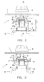
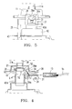
- a preferred embodiment of the gas tap 1 provided with an electric switch 2 is assembled on a control panel 3 of a flat domestic cooker hob, wherein the gas tap 1 is of the type with a rotary operating shaft 50 with a conical regulating member and a thermo-electric safety valve incorporated into a conduit, and operated by means of an axial displacement of the operating shaft 50.
- the gas tap 1 comprises a tap body 40 with an input "I” and an output “O” of the flow regulated by the rotation of a control knob 10 attached to the operating shaft 50, and a metallic tap cover 42 provided with a metallic tubular member 42a that guides the movements of rotation and translation of said operating shaft 50.
- the electric switch 2 is assembled concentrically to the operating shaft 50, between the control panel 3 of the cooker and the tap body 40.
- a protective cap 11 covers the electric switch 2 from the waste and dirt on the cooker hob.
- the electric switch 2 comprises a plate-contactor 30 formed by an elastic metallic sheet, and provided with two elastic contact tabs 33 and a single external connection terminal 31, and a casing-support 20 made of insulating material, and formed by a pushing means 21, a positioning means 25 in the form of a rod for the angular positioning of the casing-support 20 around the operating shaft 50, and a cavity 24 for the housing of the connection terminal 31.
- the plate-contactor 30 is formed by a ring-shaped body 35 with the connection terminal 31 extended radially from the periphery and the two elastic contact tabs 33 extended transversally from the periphery and diametrically opposed in order to embrace the tubular member 42a of the cover 42 of the tap body, effecting a contact pressure on its cylindrical surface.
- the connection terminal 31 is connected to the ring-shaped body 35 by means of a flexible member 34 inclined in relation to the plane that forms the ring-shaped body 35.
- the plate-contactor 30 has a central orifice 32 with an expansion opening 35a in the ring-shaped body, through which it is fitted under pressure on a tubular projection 22 in the insulating pushing means 21, the plate-contactor 30 thus being fixed under pressure, for its subsequent joint assembly on the tap operating shaft 50.
- the insulating casing-support 20 is formed by said pushing means 21 and its tubular projection 22, and also with a straight support wall 26 extended to one side from the periphery of the pushing means 21, and other two radial walls 27 projecting from the support wall 26, between which they configure said housing cavity 24 for the connection terminal 31.
- the positioning means 25 extends in an axial direction a specific length "L" (Fig. 2), adjacent to the pushing means 21. The end of the positioning means 25 is inserted into an ear 43 of the metallic tap cover 42, blocking the rotation of the casing-support 20 and the metallic plate-contactor 30.
- Fig. 2 shows the electric switch 2 in the "open” state, the control knob 10 and the operating shaft 50 being extended in the rest position.
- the contact tabs 33 are separated from the tubular member 42a of the tap cover 42.
- Fig. 3 shows the electric switch in the "closed” state.
- the operating shaft 50 is retracted inside the tap body 40, and the contact tabs 33 are embracing the tubular member 42a, connecting the connection terminal 31 to the electric mass of the gas tap 1 and the cooker.
- the pushing means 21 and its tubular projection 22 have a central opening 23 with an expansion groove 21a for its fitting under pressure on the tap operating shaft 50, being kept here in a fixed position in relation to the tap body 40, 42, with the assistance of a diameter step 52 on the tap operating shaft 50, against which the tubular projection 22 of the pushing means 21 makes a positioning stop (Fig. 2 and 4).
- the control knob 10 and the operating shaft 50 are displaced inside the tap 1 by a stroke "A" (shown in Fig. 2) of, for example, 2,5 mm, the end of said stroke "A” being delimitated by a magnetic group incorporated into the tap 40 (not shown in figures).
- connection terminal 31 is introduced first of all (Fig. 1) through a window 26a in the support wall 26 of the casing-support 20; secondly (Fig. 4) the ring-shaped body 35 of the plate-contactor 30 is fitted through its central orifice 32 into the tubular projection 22 of the insulating pushing means 21, with the assistance of the intermediate flexible member 34 of the plate-contactor 20; next (Fig. 5) the connection terminal 31 is fitted under pressure in an opening 29 in the form of the V-shaped channel of the cavity 24 on the side opposite to the pushing means 21. In this opening 29 is fitted the connection terminal 31 in profile, while the intermediate flexible member 34 remains supported on an inclined surface 29a of the cavity 24 (Fig. 4).
- connection terminal 31 thus remains in a fixed position inside the casing support 20 in order to receive a female "fast-on" connection terminal 15 of a conductor wire of a voltage signal Vs.
- the radial walls 27 that delimit the cavity 24 in the casing-support 20 have above them a retention means 28, a structure in the form of an arch, with an opening in the middle 28a, through which is positioned the connection terminal 31 in a fixed position on the opening 29, and the structure 28 also enables the introduction of the female "fast-on" connection terminal 15 from the outside of the gas tap 1 and its retention connected inside the cavity 24.
- the protective cap 11 is in the form of a substantially cylindrical hat and made of a flexible material, being assembled on the tap operating shaft 50 last of all, behind the control panel 3.
- the protective cap 11 has a narrow neck 11a that is fixed on a throat 51 of the operating shaft 50 to form an airtight seal, and is displaced with the operating shaft 50 accompanying the plate-contactor 30 and its casing-support 20.
Landscapes
- Engineering & Computer Science (AREA)
- Chemical & Material Sciences (AREA)
- Combustion & Propulsion (AREA)
- Mechanical Engineering (AREA)
- General Engineering & Computer Science (AREA)
- Feeding And Controlling Fuel (AREA)
- Rotary Switch, Piano Key Switch, And Lever Switch (AREA)
Applications Claiming Priority (1)
| Application Number | Priority Date | Filing Date | Title |
|---|---|---|---|
| ES200600352U ES1062279Y (es) | 2006-02-17 | 2006-02-17 | "grifo de gas rotatorio con un interruptor electrico" |
Publications (1)
| Publication Number | Publication Date |
|---|---|
| EP1830131A2 true EP1830131A2 (de) | 2007-09-05 |
Family
ID=36593378
Family Applications (1)
| Application Number | Title | Priority Date | Filing Date |
|---|---|---|---|
| EP20070380035 Withdrawn EP1830131A2 (de) | 2006-02-17 | 2007-02-13 | Gasdrehhahn mit elektrischem Schalter |
Country Status (2)
| Country | Link |
|---|---|
| EP (1) | EP1830131A2 (de) |
| ES (1) | ES1062279Y (de) |
Cited By (3)
| Publication number | Priority date | Publication date | Assignee | Title |
|---|---|---|---|---|
| EP2461225A1 (de) * | 2010-12-03 | 2012-06-06 | BSH Bosch und Siemens Hausgeräte GmbH | Schwertknebel für ein Haushaltsgerät und Haushaltsgerät |
| WO2016016773A1 (en) * | 2014-07-29 | 2016-02-04 | Castfutura S.P.A. | Flame ignition control device for burners or the like |
| EP3839351A1 (de) * | 2019-12-17 | 2021-06-23 | Illinois Tool Works INC. | Schaltermontage zur steuerung der zündung von gasbrennern eines kochgeräts |
-
2006
- 2006-02-17 ES ES200600352U patent/ES1062279Y/es not_active Expired - Fee Related
-
2007
- 2007-02-13 EP EP20070380035 patent/EP1830131A2/de not_active Withdrawn
Cited By (3)
| Publication number | Priority date | Publication date | Assignee | Title |
|---|---|---|---|---|
| EP2461225A1 (de) * | 2010-12-03 | 2012-06-06 | BSH Bosch und Siemens Hausgeräte GmbH | Schwertknebel für ein Haushaltsgerät und Haushaltsgerät |
| WO2016016773A1 (en) * | 2014-07-29 | 2016-02-04 | Castfutura S.P.A. | Flame ignition control device for burners or the like |
| EP3839351A1 (de) * | 2019-12-17 | 2021-06-23 | Illinois Tool Works INC. | Schaltermontage zur steuerung der zündung von gasbrennern eines kochgeräts |
Also Published As
| Publication number | Publication date |
|---|---|
| ES1062279U (es) | 2006-06-16 |
| ES1062279Y (es) | 2006-09-16 |
Similar Documents
| Publication | Publication Date | Title |
|---|---|---|
| US9593855B2 (en) | Control device for gas taps | |
| US9696041B2 (en) | Control device for gas taps | |
| TWI559352B (zh) | A grounding device, a grounding device body, and a method for attaching a grounding device to a switch device element | |
| US10788217B2 (en) | Lighting control switch harness for gas taps with optical indication of opening of the gas tap, for cooking appliances | |
| USRE31596E (en) | Electric power controllers | |
| US9706872B2 (en) | Control device for gas taps | |
| CN102306559A (zh) | 一种动静触头连接组件及其高压隔离接地开关 | |
| US11085638B2 (en) | Device for controlling the ignition of gas burners of a domestic cooking appliance | |
| US6541721B1 (en) | Electrical switch for gas cocks | |
| US4658116A (en) | Hand-held electrical appliances | |
| EP3175176B1 (de) | Flammenzündsteuerungsvorrichtung für brenner oder dergleichen | |
| WO2014058716A1 (en) | Valve system for gas cooking range with integrated ignition switch | |
| CN101326604B (zh) | 接地断路器和制造这种接地断路器的方法 | |
| US3057976A (en) | Acceleration switch | |
| CN216288298U (zh) | 一种10kV空气常压组合式开关模块 | |
| ES1062279U (es) | "grifo de gas rotatorio con un interruptor electico". | |
| CN101213405A (zh) | 煤气燃烧器的火焰点火装置 | |
| US11195672B2 (en) | Switch element for tap changer, and tap changer | |
| EP2090368A1 (de) | Verbesserter Duschkopf mit Umschaltung der Ausgabeart | |
| US4739133A (en) | Electrical switching apparatus | |
| CN105333404B (zh) | 照明装置的端盖和照明装置 | |
| EP2868978A1 (de) | Haushaltsgerät mit einer Tastenbuchse | |
| WO2023129033A2 (en) | Push-button type switch system for gas-burning stoves | |
| EP0152238A2 (de) | Elektrische Handgeräte | |
| EP3772613A1 (de) | Übertragungsmechanismus für druckknopfschalter |
Legal Events
| Date | Code | Title | Description |
|---|---|---|---|
| PUAI | Public reference made under article 153(3) epc to a published international application that has entered the european phase |
Free format text: ORIGINAL CODE: 0009012 |
|
| AK | Designated contracting states |
Kind code of ref document: A2 Designated state(s): AT BE BG CH CY CZ DE DK EE ES FI FR GB GR HU IE IS IT LI LT LU LV MC NL PL PT RO SE SI SK TR |
|
| AX | Request for extension of the european patent |
Extension state: AL BA HR MK YU |
|
| RAP1 | Party data changed (applicant data changed or rights of an application transferred) |
Owner name: BSH BOSCH UND SIEMENS HAUSGERAETE GMBH Owner name: COPRECITEC, S.L. |
|
| RIN1 | Information on inventor provided before grant (corrected) |
Inventor name: PLACER MARURAI, EMILIO Inventor name: PALACIOS VALDUEZA, LUIS ANTONIO Inventor name: LEON GARCIA, JOSE Inventor name: HERRERA ESTRADA, PEDRO Inventor name: MUTILOA, AMAIA SALBIDE |
|
| RIN1 | Information on inventor provided before grant (corrected) |
Inventor name: PLACER MARURI, EMILIO Inventor name: PALACIOS VALDUEZA, LUIS ANTONIO Inventor name: LEON GARCIA, JOSE Inventor name: HERRERA ESTRADA, PEDRO Inventor name: SALBIDE MUTILOA, AMAIA |
|
| RAP1 | Party data changed (applicant data changed or rights of an application transferred) |
Owner name: BSH HAUSGERAETE GMBH Owner name: COPRECITEC, S.L. |
|
| STAA | Information on the status of an ep patent application or granted ep patent |
Free format text: STATUS: THE APPLICATION HAS BEEN WITHDRAWN |
|
| 18W | Application withdrawn |
Effective date: 20161024 |