EP1830370B1 - Dispositif destiné à la commande d'un mécanisme de commande électromagnétique - Google Patents
Dispositif destiné à la commande d'un mécanisme de commande électromagnétique Download PDFInfo
- Publication number
- EP1830370B1 EP1830370B1 EP20070004336 EP07004336A EP1830370B1 EP 1830370 B1 EP1830370 B1 EP 1830370B1 EP 20070004336 EP20070004336 EP 20070004336 EP 07004336 A EP07004336 A EP 07004336A EP 1830370 B1 EP1830370 B1 EP 1830370B1
- Authority
- EP
- European Patent Office
- Prior art keywords
- current
- supply voltage
- switching
- voltage
- power
- Prior art date
- Legal status (The legal status is an assumption and is not a legal conclusion. Google has not performed a legal analysis and makes no representation as to the accuracy of the status listed.)
- Active
Links
Images


Classifications
-
- H—ELECTRICITY
- H01—ELECTRIC ELEMENTS
- H01F—MAGNETS; INDUCTANCES; TRANSFORMERS; SELECTION OF MATERIALS FOR THEIR MAGNETIC PROPERTIES
- H01F7/00—Magnets
- H01F7/06—Electromagnets; Actuators including electromagnets
- H01F7/08—Electromagnets; Actuators including electromagnets with armatures
- H01F7/18—Circuit arrangements for obtaining desired operating characteristics, e.g. for slow operation, for sequential energisation of windings, for high-speed energisation of windings
- H01F7/1805—Circuit arrangements for holding the operation of electromagnets or for holding the armature in attracted position with reduced energising current
- H01F7/1811—Circuit arrangements for holding the operation of electromagnets or for holding the armature in attracted position with reduced energising current demagnetising upon switching off, removing residual magnetism
-
- F—MECHANICAL ENGINEERING; LIGHTING; HEATING; WEAPONS; BLASTING
- F02—COMBUSTION ENGINES; HOT-GAS OR COMBUSTION-PRODUCT ENGINE PLANTS
- F02D—CONTROLLING COMBUSTION ENGINES
- F02D41/00—Electrical control of supply of combustible mixture or its constituents
- F02D41/20—Output circuits, e.g. for controlling currents in command coils
-
- H—ELECTRICITY
- H01—ELECTRIC ELEMENTS
- H01F—MAGNETS; INDUCTANCES; TRANSFORMERS; SELECTION OF MATERIALS FOR THEIR MAGNETIC PROPERTIES
- H01F7/00—Magnets
- H01F7/06—Electromagnets; Actuators including electromagnets
- H01F7/08—Electromagnets; Actuators including electromagnets with armatures
- H01F7/18—Circuit arrangements for obtaining desired operating characteristics, e.g. for slow operation, for sequential energisation of windings, for high-speed energisation of windings
- H01F7/1844—Monitoring or fail-safe circuits
-
- F—MECHANICAL ENGINEERING; LIGHTING; HEATING; WEAPONS; BLASTING
- F02—COMBUSTION ENGINES; HOT-GAS OR COMBUSTION-PRODUCT ENGINE PLANTS
- F02D—CONTROLLING COMBUSTION ENGINES
- F02D41/00—Electrical control of supply of combustible mixture or its constituents
- F02D41/20—Output circuits, e.g. for controlling currents in command coils
- F02D2041/2003—Output circuits, e.g. for controlling currents in command coils using means for creating a boost voltage, i.e. generation or use of a voltage higher than the battery voltage, e.g. to speed up injector opening
-
- F—MECHANICAL ENGINEERING; LIGHTING; HEATING; WEAPONS; BLASTING
- F02—COMBUSTION ENGINES; HOT-GAS OR COMBUSTION-PRODUCT ENGINE PLANTS
- F02D—CONTROLLING COMBUSTION ENGINES
- F02D41/00—Electrical control of supply of combustible mixture or its constituents
- F02D41/20—Output circuits, e.g. for controlling currents in command coils
- F02D2041/202—Output circuits, e.g. for controlling currents in command coils characterised by the control of the circuit
- F02D2041/2024—Output circuits, e.g. for controlling currents in command coils characterised by the control of the circuit the control switching a load after time-on and time-off pulses
- F02D2041/2027—Control of the current by pulse width modulation or duty cycle control
-
- F—MECHANICAL ENGINEERING; LIGHTING; HEATING; WEAPONS; BLASTING
- F02—COMBUSTION ENGINES; HOT-GAS OR COMBUSTION-PRODUCT ENGINE PLANTS
- F02D—CONTROLLING COMBUSTION ENGINES
- F02D41/00—Electrical control of supply of combustible mixture or its constituents
- F02D41/20—Output circuits, e.g. for controlling currents in command coils
- F02D2041/202—Output circuits, e.g. for controlling currents in command coils characterised by the control of the circuit
- F02D2041/2058—Output circuits, e.g. for controlling currents in command coils characterised by the control of the circuit using information of the actual current value
-
- H—ELECTRICITY
- H01—ELECTRIC ELEMENTS
- H01F—MAGNETS; INDUCTANCES; TRANSFORMERS; SELECTION OF MATERIALS FOR THEIR MAGNETIC PROPERTIES
- H01F7/00—Magnets
- H01F7/06—Electromagnets; Actuators including electromagnets
- H01F7/08—Electromagnets; Actuators including electromagnets with armatures
- H01F7/18—Circuit arrangements for obtaining desired operating characteristics, e.g. for slow operation, for sequential energisation of windings, for high-speed energisation of windings
- H01F7/1805—Circuit arrangements for holding the operation of electromagnets or for holding the armature in attracted position with reduced energising current
- H01F7/1816—Circuit arrangements for holding the operation of electromagnets or for holding the armature in attracted position with reduced energising current making use of an energy accumulator
- H01F2007/1822—Circuit arrangements for holding the operation of electromagnets or for holding the armature in attracted position with reduced energising current making use of an energy accumulator using a capacitor to produce a boost voltage
-
- H—ELECTRICITY
- H01—ELECTRIC ELEMENTS
- H01F—MAGNETS; INDUCTANCES; TRANSFORMERS; SELECTION OF MATERIALS FOR THEIR MAGNETIC PROPERTIES
- H01F7/00—Magnets
- H01F7/06—Electromagnets; Actuators including electromagnets
- H01F7/08—Electromagnets; Actuators including electromagnets with armatures
- H01F7/18—Circuit arrangements for obtaining desired operating characteristics, e.g. for slow operation, for sequential energisation of windings, for high-speed energisation of windings
- H01F2007/1888—Circuit arrangements for obtaining desired operating characteristics, e.g. for slow operation, for sequential energisation of windings, for high-speed energisation of windings using pulse width modulation
Definitions
- the circuit device may have an additional control input 80.1, by which the switching on and off of the circuit itself can be controlled
Landscapes
- Physics & Mathematics (AREA)
- Electromagnetism (AREA)
- Engineering & Computer Science (AREA)
- Power Engineering (AREA)
- Chemical & Material Sciences (AREA)
- Combustion & Propulsion (AREA)
- Mechanical Engineering (AREA)
- General Engineering & Computer Science (AREA)
- Magnetically Actuated Valves (AREA)
- Electronic Switches (AREA)
Claims (11)
- Procédé de commande d'un mécanisme de réglage électromagnétique comportant un circuit de commutation, lequel comprend :- une entrée (80.2) pour la connexion à une tension d'alimentation (Uv),- une entrée (80.3) pour la connexion à la terre,- deux sorties (80.4, 80.5) pour la connexion à un élément de réglage,- au moins un élément de commutation (10,30) pour l'interruption de l'alimentation en courant,- un dispositif (20) pour la détermination du courant ;- un élément de commande (60) pour la mesure du courant et de la tension d'alimentation ainsi que pour la commande dudit au moins un élément de commutation (10,30),- un élément de réglage du mécanisme de réglage, qui est commandé par ledit au moins un élément ce commutation (10,30) par modulation de largeur de pulsations et qui est actionné de manière limitée dans le temps par sa détermination,caractérisé en ce que l'élément de réglage est surexcité, lors de la mise en marche, de manière limitée dans le temps par une puissance qui est supérieure à la puissance nominale du mécanisme de commande et en ce que l'élément de commande (60) détermine, avec cette puissance à l'aide du courant et de la valeur de la tension d'alimentation de l'élément de réglage à l'état surexcité la puissance nominale à l'aide d'une multiplicité de charges inductives différentes, connues par l'élément de commande et est ainsi fermé sur le mécanisme de réglage, lequel est éventuellement actionné par modulation de largeur de pulsations à sa puissance nominale.
- Procédé selon la revendication 1, caractérisé en ce qu'une tension modulée en largeur de pulsations est produite au moyen dudit au moins un élément de commutation (10,30) pour l'adaptation de la puissance à la puissance déterminée dans le mécanisme de réglage électromagnétique relié.
- Procédé selon la revendication 1 ou 2, caractérisé en ce que le circuit de commutation possède une entrée de commande supplémentaire (80.1), par laquelle la mise en marche et l'arrêt du circuit de commutation peut être commandée.
- Procédé selon l'une des revendications précédentes, caractérisé en ce que le dispositif (20) pour la détermination du courant et de la tension d'alimentation est intégré dans l'élément de commande (60) ou est prévu à l'extérieur ou en ce que le dispositif (20) pour la détermination du courant est intégré dans l'élément de commutation (10).
- Procédé selon l'une des revendications précédentes, caractérisé en ce que le rapport impulsion/pause du signal de tension (ULAST) produit et cadencé par au moins un desdits éléments de commande (10,30) dépend de la valeur de la tension d'alimentation (UV).
- Procédé selon l'une des revendications précédentes, caractérisé en ce que l'équation suivante
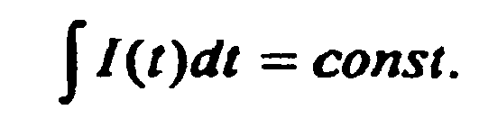
s'applique avec une tension cadencée pour le courant (ILAST) à l'état déréglé, indépendamment de la valeur de la tension d'alimentation (UV). - Procédé selon l'une des revendications précédentes, caractérisé en ce qu'au moins un point d'inflexion est utilisé dans l'augmentation du courant au moment de la mise en marche (t2, t5) pour la surveillance du fonctionnement du mécanisme de réglage.
- Procédé selon l'une des revendications précédentes, caractérisé en ce que la fréquence de commutation de la modulation de largeur de pulsations est choisie suffisamment élevée pour que l'élément d'actionnement agisse comme la bobine-mémoire d'un régulateur de commutation.
- Procédé selon l'une des revendications précédentes, caractérisé en ce que le courant de bobine et la tension s'alimentation sont de préférence mesurés à chaque cadence.
- Procédé selon l'une des revendications précédentes, caractérisé en ce que la tension d'alimentation (UV) est supérieure à la tension nominale (ULAST) de l'élément de réglage.
- Procédé selon l'une des revendications précédentes, caractérisé en que le procédé est utilisé dans une machine à mouler par injection pour la fabrication de matériaux plastifiables, en particulier dans une machine à mouler par injection pour matière plastique.
Applications Claiming Priority (1)
| Application Number | Priority Date | Filing Date | Title |
|---|---|---|---|
| DE200610009628 DE102006009628A1 (de) | 2006-03-02 | 2006-03-02 | Vorrichtung zur Steuerung eines elektromagnetischen Stellantriebs |
Publications (3)
| Publication Number | Publication Date |
|---|---|
| EP1830370A2 EP1830370A2 (fr) | 2007-09-05 |
| EP1830370A3 EP1830370A3 (fr) | 2009-04-15 |
| EP1830370B1 true EP1830370B1 (fr) | 2012-08-15 |
Family
ID=37944893
Family Applications (1)
| Application Number | Title | Priority Date | Filing Date |
|---|---|---|---|
| EP20070004336 Active EP1830370B1 (fr) | 2006-03-02 | 2007-03-02 | Dispositif destiné à la commande d'un mécanisme de commande électromagnétique |
Country Status (2)
| Country | Link |
|---|---|
| EP (1) | EP1830370B1 (fr) |
| DE (1) | DE102006009628A1 (fr) |
Cited By (1)
| Publication number | Priority date | Publication date | Assignee | Title |
|---|---|---|---|---|
| US8403880B2 (en) | 2002-05-24 | 2013-03-26 | Baxter International Inc. | Peritoneal dialysis machine with variable voltage input control scheme |
Families Citing this family (7)
| Publication number | Priority date | Publication date | Assignee | Title |
|---|---|---|---|---|
| US7746620B2 (en) | 2008-02-22 | 2010-06-29 | Baxter International Inc. | Medical fluid machine having solenoid control system with temperature compensation |
| US7782590B2 (en) * | 2008-02-22 | 2010-08-24 | Baxter International Inc. | Medical fluid machine having solenoid control system with reduced hold current |
| US8027572B2 (en) | 2008-02-22 | 2011-09-27 | Baxter International Inc. | Dialysis machine having multiple line voltage heater |
| US9435459B2 (en) | 2009-06-05 | 2016-09-06 | Baxter International Inc. | Solenoid pinch valve apparatus and method for medical fluid applications having reduced noise production |
| DE102009041451B4 (de) * | 2009-09-16 | 2012-03-15 | Küster Holding GmbH | Ansteuereinheit für elektrische und/oder pneumatische Verstellantriebe |
| DE102009044953B4 (de) | 2009-09-24 | 2019-12-05 | Robert Bosch Gmbh | Verfahren zum Ansteuern eines elektromagnetischen Verbrauchers sowie entsprechende Schaltung |
| DE102022200152B4 (de) * | 2022-01-10 | 2023-08-24 | Festo Se & Co. Kg | Magnetaktuator, Ventilanordnung und Verfahren |
Family Cites Families (7)
| Publication number | Priority date | Publication date | Assignee | Title |
|---|---|---|---|---|
| DE3910810A1 (de) * | 1989-04-04 | 1990-10-11 | Luetze Gmbh Co F | Schaltungsanordnung fuer ein elektromagnetisches ventil |
| DE4031427A1 (de) * | 1990-10-04 | 1992-04-09 | Luetze Gmbh Co F | Verfahren und vorrichtung zum energiereduzierten betrieb eines elektromagnetischen stellgliedes |
| DE4109233A1 (de) * | 1991-03-21 | 1992-09-24 | Rexroth Mannesmann Gmbh | Digitale ansteuerelektronik mit pulsweitenmoduliertem (pwm)-ausgangssignal zum ansteuern elektrischer stellglieder eines hydraulischen systems |
| US5666286A (en) | 1995-10-10 | 1997-09-09 | Nordson Corporation | Device and method for identifying a number of inductive loads in parallel |
| JP4803882B2 (ja) * | 2001-01-19 | 2011-10-26 | 本田技研工業株式会社 | 電磁アクチュエータ制御装置 |
| DE10104754A1 (de) * | 2001-02-02 | 2002-08-08 | Volkswagen Ag | Verfahren zum Betreiben eines elektromagnetischen Ventils |
| US7054772B2 (en) * | 2003-09-30 | 2006-05-30 | Delphi Technologies, Inc. | Apparatus and method for monitoring and compensating for variation in solenoid resistance during use |
-
2006
- 2006-03-02 DE DE200610009628 patent/DE102006009628A1/de not_active Withdrawn
-
2007
- 2007-03-02 EP EP20070004336 patent/EP1830370B1/fr active Active
Cited By (2)
| Publication number | Priority date | Publication date | Assignee | Title |
|---|---|---|---|---|
| US8403880B2 (en) | 2002-05-24 | 2013-03-26 | Baxter International Inc. | Peritoneal dialysis machine with variable voltage input control scheme |
| US9504778B2 (en) | 2002-05-24 | 2016-11-29 | Baxter International Inc. | Dialysis machine with electrical insulation for variable voltage input |
Also Published As
| Publication number | Publication date |
|---|---|
| EP1830370A3 (fr) | 2009-04-15 |
| DE102006009628A1 (de) | 2007-09-06 |
| EP1830370A2 (fr) | 2007-09-05 |
Similar Documents
| Publication | Publication Date | Title |
|---|---|---|
| EP1830370B1 (fr) | Dispositif destiné à la commande d'un mécanisme de commande électromagnétique | |
| EP1872378B1 (fr) | Detection de position sans capteur dans un actionneur electromagnetique | |
| EP2603807B1 (fr) | Procédé et dispositif de détermination de l'état d'une vanne à commande électrique | |
| DE102016221477A1 (de) | Vorrichtung zum Betreiben und zur Ermittlung eines Betriebszustands eines elektromagnetischen Aktors sowie Kupplungsvorrichtung und Kraftfahrzeugantriebsstrang | |
| WO2009135824A1 (fr) | Procédé et dispositif permettant de commander une servocommande | |
| DE4434179A1 (de) | Schaltungsanordnung zur Überwachung einer Steuerschaltung | |
| EP1347908B1 (fr) | Dispositif de commande de soupapes de frein | |
| EP0765438A1 (fr) | Procede et dispositif de commande d'un consommateur electromagnetique | |
| EP2193534A1 (fr) | Dispositif et procédé d'alimentation électrique d'un commutateur à déclenchement de tension ou d'intensité | |
| DE10315282B4 (de) | Schaltungsanordnung und Verfahren zur Ansteuerung eines bistabilen Magnetventils | |
| EP1234316A1 (fr) | Appareil de commutation electromagnetique a commande asservie et procede et circuit correspondants | |
| DE102012206419B4 (de) | Steuerung für ein Druckregelventil | |
| EP3381119B1 (fr) | Procédé de régulation en courant d'une charge inductive | |
| WO2008086909A1 (fr) | Procédé de réglage d'un débit volumique | |
| DE102007034768B3 (de) | Elektrischer Hubmagnet | |
| EP1031182B1 (fr) | Procede et circuit pour la production d'un signal de reglage a modulation d'impulsions en largeur pour un actionneur a courant continu | |
| EP1703629B1 (fr) | Procédé pour la commande digitale de courant | |
| DE102004056653B4 (de) | Schaltungsanordnung zum Erkennen des Schaltens eines Magnetankers | |
| EP1659831B1 (fr) | Dispositif d'eclairage pour voiture avec des LED's | |
| EP3915185A1 (fr) | Système d'entraînement et procédé servant à faire fonctionner un système d'entraînement comprenant un frein à actionnement électromagnétique | |
| DE102013219864A1 (de) | Spulenansteuerung | |
| WO2010118978A2 (fr) | Procédé pour utiliser un circuit de commande, en particulier pour une application sur un véhicule automobile | |
| DE102019203574B4 (de) | Ventilanordnung und Verfahren | |
| DE19725317B4 (de) | Schaltungsanordnung zur Ansteuerung eines mit Gleichspannung betätigbaren Magnetventiles | |
| DE102012204122B4 (de) | Elektronische PWM-Ansteuerschaltung zur Ansteuerung von Lasten, insbesondere Magnetventilen, PWM-Ansteuerverfahren sowie deren bzw. dessen Verwendung |
Legal Events
| Date | Code | Title | Description |
|---|---|---|---|
| PUAI | Public reference made under article 153(3) epc to a published international application that has entered the european phase |
Free format text: ORIGINAL CODE: 0009012 |
|
| AK | Designated contracting states |
Kind code of ref document: A2 Designated state(s): AT BE BG CH CY CZ DE DK EE ES FI FR GB GR HU IE IS IT LI LT LU LV MC MT NL PL PT RO SE SI SK TR |
|
| AX | Request for extension of the european patent |
Extension state: AL BA HR MK YU |
|
| PUAL | Search report despatched |
Free format text: ORIGINAL CODE: 0009013 |
|
| AK | Designated contracting states |
Kind code of ref document: A3 Designated state(s): AT BE BG CH CY CZ DE DK EE ES FI FR GB GR HU IE IS IT LI LT LU LV MC MT NL PL PT RO SE SI SK TR |
|
| AX | Request for extension of the european patent |
Extension state: AL BA HR MK RS |
|
| 17P | Request for examination filed |
Effective date: 20091013 |
|
| AKX | Designation fees paid |
Designated state(s): AT BE BG CH CY CZ DE DK EE ES FI FR GB GR HU IE IS IT LI LT LU LV MC MT NL PL PT RO SE SI SK TR |
|
| RAP3 | Party data changed (applicant data changed or rights of an application transferred) |
Owner name: HEHL, KARL |
|
| RIN1 | Information on inventor provided before grant (corrected) |
Inventor name: HEHL, KARL |
|
| 17Q | First examination report despatched |
Effective date: 20100630 |
|
| RAP1 | Party data changed (applicant data changed or rights of an application transferred) |
Owner name: KEINATH, RENATE |
|
| RIN1 | Information on inventor provided before grant (corrected) |
Inventor name: KEINATH, RENATE |
|
| GRAP | Despatch of communication of intention to grant a patent |
Free format text: ORIGINAL CODE: EPIDOSNIGR1 |
|
| GRAC | Information related to communication of intention to grant a patent modified |
Free format text: ORIGINAL CODE: EPIDOSCIGR1 |
|
| GRAS | Grant fee paid |
Free format text: ORIGINAL CODE: EPIDOSNIGR3 |
|
| GRAA | (expected) grant |
Free format text: ORIGINAL CODE: 0009210 |
|
| AK | Designated contracting states |
Kind code of ref document: B1 Designated state(s): AT BE BG CH CY CZ DE DK EE ES FI FR GB GR HU IE IS IT LI LT LU LV MC MT NL PL PT RO SE SI SK TR |
|
| REG | Reference to a national code |
Ref country code: GB Ref legal event code: FG4D Free format text: NOT ENGLISH Ref country code: CH Ref legal event code: EP Ref country code: AT Ref legal event code: REF Ref document number: 571199 Country of ref document: AT Kind code of ref document: T Effective date: 20120815 |
|
| REG | Reference to a national code |
Ref country code: IE Ref legal event code: FG4D Free format text: LANGUAGE OF EP DOCUMENT: GERMAN |
|
| REG | Reference to a national code |
Ref country code: CH Ref legal event code: NV Representative=s name: LUCHS & PARTNER AG PATENTANWAELTE |
|
| REG | Reference to a national code |
Ref country code: DE Ref legal event code: R096 Ref document number: 502007010365 Country of ref document: DE Effective date: 20121018 |
|
| REG | Reference to a national code |
Ref country code: NL Ref legal event code: VDEP Effective date: 20120815 |
|
| PG25 | Lapsed in a contracting state [announced via postgrant information from national office to epo] |
Ref country code: LT Free format text: LAPSE BECAUSE OF FAILURE TO SUBMIT A TRANSLATION OF THE DESCRIPTION OR TO PAY THE FEE WITHIN THE PRESCRIBED TIME-LIMIT Effective date: 20120815 Ref country code: FI Free format text: LAPSE BECAUSE OF FAILURE TO SUBMIT A TRANSLATION OF THE DESCRIPTION OR TO PAY THE FEE WITHIN THE PRESCRIBED TIME-LIMIT Effective date: 20120815 Ref country code: IS Free format text: LAPSE BECAUSE OF FAILURE TO SUBMIT A TRANSLATION OF THE DESCRIPTION OR TO PAY THE FEE WITHIN THE PRESCRIBED TIME-LIMIT Effective date: 20121215 Ref country code: CY Free format text: LAPSE BECAUSE OF FAILURE TO SUBMIT A TRANSLATION OF THE DESCRIPTION OR TO PAY THE FEE WITHIN THE PRESCRIBED TIME-LIMIT Effective date: 20120815 |
|
| PG25 | Lapsed in a contracting state [announced via postgrant information from national office to epo] |
Ref country code: SE Free format text: LAPSE BECAUSE OF FAILURE TO SUBMIT A TRANSLATION OF THE DESCRIPTION OR TO PAY THE FEE WITHIN THE PRESCRIBED TIME-LIMIT Effective date: 20120815 Ref country code: GR Free format text: LAPSE BECAUSE OF FAILURE TO SUBMIT A TRANSLATION OF THE DESCRIPTION OR TO PAY THE FEE WITHIN THE PRESCRIBED TIME-LIMIT Effective date: 20121116 Ref country code: PL Free format text: LAPSE BECAUSE OF FAILURE TO SUBMIT A TRANSLATION OF THE DESCRIPTION OR TO PAY THE FEE WITHIN THE PRESCRIBED TIME-LIMIT Effective date: 20120815 Ref country code: LV Free format text: LAPSE BECAUSE OF FAILURE TO SUBMIT A TRANSLATION OF THE DESCRIPTION OR TO PAY THE FEE WITHIN THE PRESCRIBED TIME-LIMIT Effective date: 20120815 Ref country code: PT Free format text: LAPSE BECAUSE OF FAILURE TO SUBMIT A TRANSLATION OF THE DESCRIPTION OR TO PAY THE FEE WITHIN THE PRESCRIBED TIME-LIMIT Effective date: 20121217 Ref country code: SI Free format text: LAPSE BECAUSE OF FAILURE TO SUBMIT A TRANSLATION OF THE DESCRIPTION OR TO PAY THE FEE WITHIN THE PRESCRIBED TIME-LIMIT Effective date: 20120815 |
|
| PG25 | Lapsed in a contracting state [announced via postgrant information from national office to epo] |
Ref country code: NL Free format text: LAPSE BECAUSE OF FAILURE TO SUBMIT A TRANSLATION OF THE DESCRIPTION OR TO PAY THE FEE WITHIN THE PRESCRIBED TIME-LIMIT Effective date: 20120815 |
|
| PG25 | Lapsed in a contracting state [announced via postgrant information from national office to epo] |
Ref country code: EE Free format text: LAPSE BECAUSE OF FAILURE TO SUBMIT A TRANSLATION OF THE DESCRIPTION OR TO PAY THE FEE WITHIN THE PRESCRIBED TIME-LIMIT Effective date: 20120815 Ref country code: ES Free format text: LAPSE BECAUSE OF FAILURE TO SUBMIT A TRANSLATION OF THE DESCRIPTION OR TO PAY THE FEE WITHIN THE PRESCRIBED TIME-LIMIT Effective date: 20121126 Ref country code: CZ Free format text: LAPSE BECAUSE OF FAILURE TO SUBMIT A TRANSLATION OF THE DESCRIPTION OR TO PAY THE FEE WITHIN THE PRESCRIBED TIME-LIMIT Effective date: 20120815 Ref country code: DK Free format text: LAPSE BECAUSE OF FAILURE TO SUBMIT A TRANSLATION OF THE DESCRIPTION OR TO PAY THE FEE WITHIN THE PRESCRIBED TIME-LIMIT Effective date: 20120815 Ref country code: RO Free format text: LAPSE BECAUSE OF FAILURE TO SUBMIT A TRANSLATION OF THE DESCRIPTION OR TO PAY THE FEE WITHIN THE PRESCRIBED TIME-LIMIT Effective date: 20120815 |
|
| PG25 | Lapsed in a contracting state [announced via postgrant information from national office to epo] |
Ref country code: SK Free format text: LAPSE BECAUSE OF FAILURE TO SUBMIT A TRANSLATION OF THE DESCRIPTION OR TO PAY THE FEE WITHIN THE PRESCRIBED TIME-LIMIT Effective date: 20120815 |
|
| PLBE | No opposition filed within time limit |
Free format text: ORIGINAL CODE: 0009261 |
|
| STAA | Information on the status of an ep patent application or granted ep patent |
Free format text: STATUS: NO OPPOSITION FILED WITHIN TIME LIMIT |
|
| 26N | No opposition filed |
Effective date: 20130516 |
|
| PG25 | Lapsed in a contracting state [announced via postgrant information from national office to epo] |
Ref country code: BG Free format text: LAPSE BECAUSE OF FAILURE TO SUBMIT A TRANSLATION OF THE DESCRIPTION OR TO PAY THE FEE WITHIN THE PRESCRIBED TIME-LIMIT Effective date: 20121115 |
|
| REG | Reference to a national code |
Ref country code: DE Ref legal event code: R097 Ref document number: 502007010365 Country of ref document: DE Effective date: 20130516 |
|
| BERE | Be: lapsed |
Owner name: KEINATH, RENATE Effective date: 20130331 |
|
| PG25 | Lapsed in a contracting state [announced via postgrant information from national office to epo] |
Ref country code: MC Free format text: LAPSE BECAUSE OF NON-PAYMENT OF DUE FEES Effective date: 20130331 |
|
| REG | Reference to a national code |
Ref country code: IE Ref legal event code: MM4A |
|
| PG25 | Lapsed in a contracting state [announced via postgrant information from national office to epo] |
Ref country code: BE Free format text: LAPSE BECAUSE OF NON-PAYMENT OF DUE FEES Effective date: 20130331 Ref country code: IE Free format text: LAPSE BECAUSE OF NON-PAYMENT OF DUE FEES Effective date: 20130302 |
|
| PG25 | Lapsed in a contracting state [announced via postgrant information from national office to epo] |
Ref country code: MT Free format text: LAPSE BECAUSE OF FAILURE TO SUBMIT A TRANSLATION OF THE DESCRIPTION OR TO PAY THE FEE WITHIN THE PRESCRIBED TIME-LIMIT Effective date: 20120815 |
|
| PG25 | Lapsed in a contracting state [announced via postgrant information from national office to epo] |
Ref country code: TR Free format text: LAPSE BECAUSE OF FAILURE TO SUBMIT A TRANSLATION OF THE DESCRIPTION OR TO PAY THE FEE WITHIN THE PRESCRIBED TIME-LIMIT Effective date: 20120815 |
|
| PG25 | Lapsed in a contracting state [announced via postgrant information from national office to epo] |
Ref country code: HU Free format text: LAPSE BECAUSE OF FAILURE TO SUBMIT A TRANSLATION OF THE DESCRIPTION OR TO PAY THE FEE WITHIN THE PRESCRIBED TIME-LIMIT; INVALID AB INITIO Effective date: 20070302 Ref country code: LU Free format text: LAPSE BECAUSE OF NON-PAYMENT OF DUE FEES Effective date: 20130302 |
|
| REG | Reference to a national code |
Ref country code: FR Ref legal event code: PLFP Year of fee payment: 10 |
|
| REG | Reference to a national code |
Ref country code: FR Ref legal event code: PLFP Year of fee payment: 11 |
|
| REG | Reference to a national code |
Ref country code: FR Ref legal event code: PLFP Year of fee payment: 12 |
|
| PGFP | Annual fee paid to national office [announced via postgrant information from national office to epo] |
Ref country code: GB Payment date: 20200325 Year of fee payment: 14 |
|
| GBPC | Gb: european patent ceased through non-payment of renewal fee |
Effective date: 20210302 |
|
| PG25 | Lapsed in a contracting state [announced via postgrant information from national office to epo] |
Ref country code: GB Free format text: LAPSE BECAUSE OF NON-PAYMENT OF DUE FEES Effective date: 20210302 |
|
| P01 | Opt-out of the competence of the unified patent court (upc) registered |
Effective date: 20230518 |
|
| PGFP | Annual fee paid to national office [announced via postgrant information from national office to epo] |
Ref country code: AT Payment date: 20240318 Year of fee payment: 18 |
|
| PGFP | Annual fee paid to national office [announced via postgrant information from national office to epo] |
Ref country code: DE Payment date: 20240229 Year of fee payment: 18 |
|
| PGFP | Annual fee paid to national office [announced via postgrant information from national office to epo] |
Ref country code: IT Payment date: 20240329 Year of fee payment: 18 Ref country code: FR Payment date: 20240320 Year of fee payment: 18 |
|
| PGFP | Annual fee paid to national office [announced via postgrant information from national office to epo] |
Ref country code: CH Payment date: 20240401 Year of fee payment: 18 |
|
| REG | Reference to a national code |
Ref country code: DE Ref legal event code: R119 Ref document number: 502007010365 Country of ref document: DE |
|
| REG | Reference to a national code |
Ref country code: CH Ref legal event code: H13 Free format text: ST27 STATUS EVENT CODE: U-0-0-H10-H13 (AS PROVIDED BY THE NATIONAL OFFICE) Effective date: 20251023 |
|
| REG | Reference to a national code |
Ref country code: AT Ref legal event code: MM01 Ref document number: 571199 Country of ref document: AT Kind code of ref document: T Effective date: 20250302 |
|
| PG25 | Lapsed in a contracting state [announced via postgrant information from national office to epo] |
Ref country code: DE Free format text: LAPSE BECAUSE OF NON-PAYMENT OF DUE FEES Effective date: 20251001 |
|
| PG25 | Lapsed in a contracting state [announced via postgrant information from national office to epo] |
Ref country code: AT Free format text: LAPSE BECAUSE OF NON-PAYMENT OF DUE FEES Effective date: 20250302 |
|
| PG25 | Lapsed in a contracting state [announced via postgrant information from national office to epo] |
Ref country code: FR Free format text: LAPSE BECAUSE OF NON-PAYMENT OF DUE FEES Effective date: 20250331 Ref country code: IT Free format text: LAPSE BECAUSE OF NON-PAYMENT OF DUE FEES Effective date: 20250302 |
|
| PG25 | Lapsed in a contracting state [announced via postgrant information from national office to epo] |
Ref country code: CH Free format text: LAPSE BECAUSE OF NON-PAYMENT OF DUE FEES Effective date: 20250331 |