EP1830461A1 - Unité d'entrainement, dispositif de réglage et procédé de commande d'un dispositif de réglage - Google Patents
Unité d'entrainement, dispositif de réglage et procédé de commande d'un dispositif de réglage Download PDFInfo
- Publication number
- EP1830461A1 EP1830461A1 EP06004160A EP06004160A EP1830461A1 EP 1830461 A1 EP1830461 A1 EP 1830461A1 EP 06004160 A EP06004160 A EP 06004160A EP 06004160 A EP06004160 A EP 06004160A EP 1830461 A1 EP1830461 A1 EP 1830461A1
- Authority
- EP
- European Patent Office
- Prior art keywords
- motor
- adjusting device
- drive unit
- vehicle
- drive
- Prior art date
- Legal status (The legal status is an assumption and is not a legal conclusion. Google has not performed a legal analysis and makes no representation as to the accuracy of the status listed.)
- Withdrawn
Links
- 238000000034 method Methods 0.000 title claims abstract description 23
- 230000007246 mechanism Effects 0.000 claims abstract description 21
- 238000010438 heat treatment Methods 0.000 claims abstract description 16
- 230000000903 blocking effect Effects 0.000 claims description 17
- 238000001514 detection method Methods 0.000 claims description 16
- 230000005540 biological transmission Effects 0.000 claims description 10
- 230000006378 damage Effects 0.000 claims description 9
- 230000001105 regulatory effect Effects 0.000 claims description 2
- 230000008901 benefit Effects 0.000 description 5
- 239000000725 suspension Substances 0.000 description 5
- 230000006870 function Effects 0.000 description 4
- 230000002441 reversible effect Effects 0.000 description 4
- 230000002349 favourable effect Effects 0.000 description 3
- 238000011144 upstream manufacturing Methods 0.000 description 3
- 238000010586 diagram Methods 0.000 description 2
- 230000007774 longterm Effects 0.000 description 2
- 230000008569 process Effects 0.000 description 2
- 230000002950 deficient Effects 0.000 description 1
- 230000001419 dependent effect Effects 0.000 description 1
- 230000002542 deteriorative effect Effects 0.000 description 1
- 238000009434 installation Methods 0.000 description 1
- 239000003973 paint Substances 0.000 description 1
- 230000002035 prolonged effect Effects 0.000 description 1
- 230000004044 response Effects 0.000 description 1
- 230000002269 spontaneous effect Effects 0.000 description 1
- 230000001960 triggered effect Effects 0.000 description 1
- 230000000007 visual effect Effects 0.000 description 1
- 238000004804 winding Methods 0.000 description 1
Images


Classifications
-
- H—ELECTRICITY
- H02—GENERATION; CONVERSION OR DISTRIBUTION OF ELECTRIC POWER
- H02P—CONTROL OR REGULATION OF ELECTRIC MOTORS, ELECTRIC GENERATORS OR DYNAMO-ELECTRIC CONVERTERS; CONTROLLING TRANSFORMERS, REACTORS OR CHOKE COILS
- H02P1/00—Arrangements for starting electric motors or dynamo-electric converters
- H02P1/16—Arrangements for starting electric motors or dynamo-electric converters for starting dynamo-electric motors or dynamo-electric converters
- H02P1/46—Arrangements for starting electric motors or dynamo-electric converters for starting dynamo-electric motors or dynamo-electric converters for starting an individual synchronous motor
-
- B—PERFORMING OPERATIONS; TRANSPORTING
- B60—VEHICLES IN GENERAL
- B60R—VEHICLES, VEHICLE FITTINGS, OR VEHICLE PARTS, NOT OTHERWISE PROVIDED FOR
- B60R22/00—Safety belts or body harnesses in vehicles
- B60R22/18—Anchoring devices
- B60R22/20—Anchoring devices adjustable in position, e.g. in height
-
- H—ELECTRICITY
- H02—GENERATION; CONVERSION OR DISTRIBUTION OF ELECTRIC POWER
- H02P—CONTROL OR REGULATION OF ELECTRIC MOTORS, ELECTRIC GENERATORS OR DYNAMO-ELECTRIC CONVERTERS; CONTROLLING TRANSFORMERS, REACTORS OR CHOKE COILS
- H02P6/00—Arrangements for controlling synchronous motors or other dynamo-electric motors using electronic commutation dependent on the rotor position; Electronic commutators therefor
- H02P6/34—Modelling or simulation for control purposes
-
- B—PERFORMING OPERATIONS; TRANSPORTING
- B60—VEHICLES IN GENERAL
- B60R—VEHICLES, VEHICLE FITTINGS, OR VEHICLE PARTS, NOT OTHERWISE PROVIDED FOR
- B60R22/00—Safety belts or body harnesses in vehicles
- B60R22/18—Anchoring devices
- B60R22/20—Anchoring devices adjustable in position, e.g. in height
- B60R2022/208—Anchoring devices adjustable in position, e.g. in height by automatic or remote control means
Definitions
- the present invention relates to a drive unit for an adjusting device for an adjustable element of a vehicle, with an electric drive, and an associated method.
- the invention further relates to an adjusting device for an adjustable element of a vehicle, with a drive unit, a transmission, an adjustable mechanism which can be coupled to the adjustable element and a position detection system for the adjustment mechanism.
- Drive units and adjusting the above-mentioned type are used for example in a belt height adjustment of a vehicle.
- the known drives and adjusting work with permanently excited DC motors, which are oversized and over-wound for overload and blocking protection of the motors. Due to the oversizing of the motors, a load susceptibility of the motors due to a lack of driving stiffness, which would manifest itself in a yelp, can be excluded.
- the known drives and adjusting devices have the disadvantage that they are large and heavy due to the large engines.
- the object of the present invention is achieved by a drive unit of the above-mentioned type, in which the electric drive is a small drive with a permanent excitable, powered above a motor rated DC motor and an electronic control for the DC motor is.
- the drive unit when using the drive unit according to the invention, a small, fast-rotating power motor can be used, which is also operated above its nominal motor power, in which range it would typically blow and therefore would not be used.
- the electronic control makes it possible, despite the use of a small motor, to provide a low-noise and well-sounding and overload-proof drive unit for the adjusting device for the adjustable element of the vehicle.
- the drive unit can be made small and lightweight.
- the electronic control comprises an electronic speed control for the DC motor.
- the speed of the small DC motor used can be set so that a yaw of the engine is avoided under load.
- the electronic control includes an electronic overload and blocking fuse for the DC motor. Thanks to the intelligent electronics, it is possible to ensure that the drive unit is overload-proof and that it restarts intelligently after a blockage.
- the DC motor has an operating power of up to about 5 watts, preferably from about 0.2 watts to about 1.5 watts.
- Motors with a power range up to 5 watts are small and light and therefore particularly well suited to provide the drive unit space-saving and with low weight in the vehicle.
- Motors in the power range of about 0.2 watts to about 1.5 watts are very small and lightweight, so that when you use the drive unit can be made very compact and lightweight.
- the electronic control for the DC motor is coupled to a processor.
- the small motor can be monitored during operation, so that an intelligent overload and blocking protection for the DC motor is ensured.
- the drive unit forms a drive for a plurality of adjustable elements of the vehicle.
- the power provided by the engine can be utilized by multiple adjustable elements of the vehicle.
- the object of the invention is further achieved by an adjusting device of the above-mentioned type, in which the drive unit has a small drive with a permanently excitable, driven above a rated motor power DC motor and an electronic control for the DC motor.
- the entire adjustment can be space-saving and easily permitted. It is also possible that the drive unit is provided as close to the element to be adjusted.
- the adjusting device according to the invention makes it possible, despite a reduced weight and smaller installation space for the drive unit, to provide a low-noise and well-sounding adjustment of the adjustable element while at the same time providing overload-proof function of the drive unit.
- the electronic control of the drive unit of the adjusting device may include an electronic speed control for the DC motor and / or an electronic overload and blocking protection for the DC motor.
- the DC motor of the drive unit of the adjustment device may have an operating power of up to about 5 watts, preferably from about 0.2 watts to about 1.5 watts.
- electronic control for the DC motor of the drive unit of the adjusting device is coupled to a processor.
- the drive unit of the adjusting device forms the drive for a plurality of adjustable elements of the vehicle.
- the position detection system has at least one Hall sensor, and at least one magnet is provided on the adjustment mechanism.
- the Hall sensor By the Hall sensor, a movement of the adjusting mechanism can be detected, whereby a current position of the element to be adjusted can be detected.
- the adjusting mechanism has a spindle
- the position detecting system comprises a counter, an A / D converter and a memory for counting and storing revolutions of the spindle.
- This embodiment of the invention is particularly well suited to determine the position of the element to be adjusted on the basis of the number of revolutions of the spindle.
- the position detection system comprises a potentiometer.
- the potentiometer is a continuously adjustable voltage divider whose resistance value can be changed as a function of the position of the element to be adjusted or of the adjustment system. In this way, the position of the element to be adjusted or the adjustment without electronic memory or counter can be determined.
- the position detection system is coupled to a processor.
- the processor can intelligently process values which are determined with the position detection system and then intelligently control the position detection system.
- the processor is connected to a CAN bus of the vehicle.
- a respective current position information of the element to be adjusted can be received by the vehicle CAN bus or predetermined by the CAN bus, whereby the control of the element to be adjusted can be performed from a central location in the vehicle.
- the transmission of the adjusting device is a planetary gear.
- a planetary gear can be kept small in comparison to a spur gear, which is basically also used, whereby the entire adjustment can be made small and lightweight.
- Helical planetary gears such as planetary gear with helical plastic wheels, have the advantage that they work very quietly.
- the adjustment is a Gurt bannverstell tristearspin.
- the advantages of the adjustment as their smallness and their low weight to Belt height adjustment can be used, the Gurt bannverstellINA can be placed close to the belt to be adjusted without disturbing.
- the adjusting device is an interior mirror adjusting device.
- the small and light adjusting device can be mounted in the vicinity of or on an inner mirror without deteriorating the visual impression of a vehicle interior.
- the object of the invention is further achieved by a method for driving an adjusting device for an adjustable element of a vehicle, with an electric drive, wherein the electric drive is a small drive with a permanent-magnet DC motor, which is operated above a rated power of the DC motor and is turned off, before reaching a critical heating limit of the DC motor.
- the electric drive is a small drive with a permanent-magnet DC motor, which is operated above a rated power of the DC motor and is turned off, before reaching a critical heating limit of the DC motor.
- the small drive can be operated in a power range in which it would typically blow, which application is described in practice as a misuse.
- the small engine can be expected to perform as well as a large one without the risk of the engine burning out.
- the entire adjustment can be made small and lightweight and thus much more variable than the previous large, heavy adjustment in or on the vehicle.
- the critical heating limit is a temperature which the DC motor still bears without damage, with temperatures above the critical heating limit resulting in engine damage.
- the critical heating limit is a temperature which the DC motor still bears without damage, with temperatures above the critical heating limit resulting in engine damage.
- the critical heating limit is about 110 ° C to about 130 ° C. Below this temperature limit can be guaranteed over short periods of operation of the DC motor that it does not burn.
- the speed of the DC motor can be set in an intelligent manner below the critical heating limit of the DC motor and, if necessary, downshifted.
- the power of the DC motor is electronically downshifted before reaching an overload or a blocking of the DC motor.
- the DC motor control power can be adjusted so that it does not burn out.
- a belt of the vehicle is adjusted in height by the method.
- the method according to the invention makes it possible to adjust the height of the belt of the vehicle by means of a small, lightweight device which works with high efficiency for a long time.
- the method adjusts an interior mirror of the vehicle.
- the advantages of the method according to the invention can be used to adjust the rearview mirror with the aid of a small motor, which can be flexibly mounted on or in the vicinity of an interior mirror of the vehicle.
- FIG. 1 shows a schematic view of an adjusting device 2 with a drive unit 20 according to the present invention.
- the adjustment device 2 shown is a belt height adjustment device which serves to adjust the height of a belt suspension 18 attached to the adjustment device 2 by means of a fastening 21.
- a belt suspension 18 is attached, for example, to one side of a seat of the vehicle or to the vehicle body.
- the vehicle adjusting device 2 has an adjusting mechanism 8, which comprises a spindle 12. With the help of the spindle 12, the belt suspension 18 can be adjusted according to the movement direction indicated by the arrows Y up or down.
- the spindle 12 is operated by means of a transmission 7, which is coupled to the adjusting mechanism 8.
- the transmission 7 is in the example shown a helical planetary gear, but may also be in other embodiments of the invention, for example, a spur gear.
- the helical planetary gear used in the example of Figure 1 has the advantage over the front-wheel drive that it operates much quieter.
- the transmission 7 is operated by a DC motor 3.
- the DC motor 3 is very small and light in relation to motors heretofore used in the art for adjustable element adjusters on a vehicle.
- a DC motor 3 with a rated power of 0.2 watts and a weight of 18 grams is used.
- generally DC motors 3 with a rated power of up to about 5 Watts are particularly well suited for use in the adjustment devices 2 shown in FIGS. 1 and 2, since they are small and light.
- Particularly favored are DC motors 3 with a nominal power of about 0.2 to about 1.5 watts, which are particularly small and light.
- the DC motor 3 operates in a relatively high power P region with a comparatively low weight of the DC motor 3.
- the low mass of the DC motor 3 used results from having a small number of turns with a thick wire. According to the low winding resistance achieved by such DC motors 3 are sensitive to overload.
- the DC motor 3 is operated above its nominal motor power P N. In this area, power abuse typically leads to the destruction of the DC motor 3.
- the DC motor 3 is, however, equipped with an electronic control 4, 5, which prevents destruction of the DC motor 3 during operation at such high powers.
- the electronic control includes an electronic speed control 4 and an electronic overload and blocking fuse 5 for the DC motor 3.
- the electronic speed control 4 With the help of the electronic speed control 4, a whine of the DC motor 3, which typically occurs at high load due to lack of driving stiffness of the small motor 3, prevented become.
- the overload and blocking fuse 5 includes a current control for the DC motor 3.
- the DC motor 3, which would burn out in case of overload in case of blocking after a few seconds is switched off in time by the overload and blocking fuse 5 or down-regulated, so that it works overload safe and after a Blockade starts smart again.
- the permanently excited, above its nominal motor power P N operated DC motor 3 and the electronic control 4, 5 for the DC motor 3 form a small drive 20 for the adjusting device 2 from.
- the small drive 20 is so small and light that it can be mounted in a compact form with the gear 7 directly to the adjustment mechanism 8 for the adjustable element 18. With the aid of the drive unit 20 according to the invention, it is therefore not necessary to provide the DC motor 3 at a location far away from the element 18 to be adjusted in the vehicle.
- a magnet 11 is applied to the spindle 12.
- a Hall sensor 10 is provided.
- 11 movements and thus revolutions u of the spindle 12 are detected in conjunction with the magnet 12 provided on the spindle 12.
- the magnet 11 and the Hall sensor 10 are components of a position detection system 9, which also includes a counter 13 for counting the revolutions u of the spindle 12, an A / D converter 14 for converting the detected analog data into digital data and a memory 23 for storing the Revolutions u of the spindle belong.
- the memory 23 is an actual value memory.
- FIG. 2 shows another embodiment of an adjusting device 2 according to the present invention.
- the adjusting device 2 shown in Figure 2 also has a drive unit 20 with a permanently energized, operated above a rated motor power P N DC motor 3 and an electronic control unit 4, 5 for the DC motor 3.
- the DC motor 3 drives via the gear 7, the adjustment mechanism 8 of the adjustment 2 on.
- a position detection system 9 instead of a magnetic position detection system, a position detection system 9 with a potentiometer 16 is used.
- the potentiometer 16 also measures the revolutions u of the spindle 12 of the adjusting mechanism 8 and returns the respective current position of the adjustable element 18 for the position control to an external on-board computer by means of analog values.
- FIG. 3 shows schematically the mode of operation of the adjusting device 2 shown in FIG.
- a magnet 11 is mounted, which is a Hall sensor 10 opposite.
- the magnet 11 is moved and, at a position opposite the Hall sensor 10, a signal is triggered at the Hall sensor 10.
- the signal detected by the Hall sensor 10 is transmitted to a processor 6.
- the processor 6 is coupled to the CAN bus 17 of the vehicle and receives via the CAN bus 17 a setpoint, which indicates up to which position the adjusting device 2 is to adjust the adjustable element 18.
- the processor 6 is coupled to the actual value memory 23, in which the respective current revolutions u of the spindle 12 are stored.
- the processor 6 is additionally coupled to a program memory 15 in which a program for setting the element 18 to be adjusted, for example as a function of the user of the vehicle, is stored.
- the spindle 12 is driven by the gear 7, which in the example shown is a planetary gear with helical plastic wheels.
- the transmission 7 is driven by the DC motor 3, the electronic speed control 4 and the electronic overload and blocking fuse 5 is connected upstream.
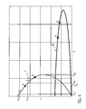
- FIG. 4 shows a diagram in which the rotational speed n of DC motors 3, 28 is schematically plotted against the power P of DC motors 3, 28.
- the mode of operation and the operating range used in the adjusting device 2 will be explained in more detail below in comparison with previously used, good-natured motors 28.
- the DC motor 3 operates in a thermally stable region or in the region of fatigue strength in which it can be operated without problems for a long time. From a point of the characteristic curve of the DC motor 3, which is indicated schematically in Figure 4 with A, enters a range D for the DC motor 3, in which he works in the so-called time stability. In this thermally fixed, dependent on the duty cycle range, the DC motor 3 can be operated in a calculable frame under technically manageable conditions. However, prolonged operation in this area or greater stresses on the DC motor 3 in this area can lead to failure of the DC motor 3.
- the point A corresponds approximately to a rated power P N given by a manufacturer without specifying a duty cycle for the DC motor 3.
- Various manufacturers also specify nominal powers P N in connection with a switch-on duration, which would have to be classified in the region D in the scheme shown in FIG ,
- the continuous characteristic curve shown in FIG. 4 represents the dependence of the rotational speed n on the power P for a large, over-wound and over-dimensioned engine which is used in the prior art for adjusting elements in the vehicle. Due to the oversizing, the large motor 28 can be operated at much higher power P than the small DC motor 3. Also, the large motor 28 has areas of fatigue strength and fatigue life, which are characterized by the letters A, B, which, however, are at much higher powers P than those areas in the DC motor 3. Accordingly, in the large, good-natured engine 28, there is no danger that it will burn out. On the other hand, the good-natured engine 28 has a large footprint and a large weight.
- the small DC motor 3 is operated according to the present invention for a short time and outside its nominal technical specification, ie above P N. This use can already be described as abuse of the DC motor 3.
- the DC motor 3 is operated within and in technically controllable, short-term regions of the time stability, that is to say in the region D of FIG. 4. By the electronic control for the DC motor 3, this can be operated in a calculable frame even outside the range of the time stability, that is above the point B in Figure 4 briefly without this burns through, for example, in the time to response of the blocking.
- the DC motor 3 for example, must be operated only briefly for operating the adjusting device 2 for belt height adjustment or adjustment, it can be adjusted by means of electronic control so that it easily survives this short overload period, without overdimensioning the DC motor 3 would be required ,
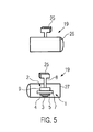
- FIG. 5 shows schematically a front and a rear view of an interior mirror 19.
- the rearview mirror 19 is attached to the vehicle by means of a suspension 25.
- a power supply for the adjustment 2 can be provided.
- the adjusting device 2 may also have an internal battery.
- the interior mirror 19 is shown above with its visible side 26.
- an open rear side 27 of the inner mirror 19 can be seen.
- the adjusting device 2 is housed, which is covered in practice with a cover, not shown in Figure 5.
- the adjusting device 2 is operated with a small drive 20, which in the example shown, the permanently excited, operated above its nominal motor power P N DC motor 3, an electronic control with the electronic speed control 4 and the electronic overload and blocking 5 has.
- the DC motor 3 drives the gear 7, which in turn drives an adjusting mechanism 8 for the rearview mirror 19.
- the inner mirror 19 can be pivoted in several directions.
- a position detection system 9 is provided for the adjusting mechanism 8, with which the respective position of the inner mirror 19 can be detected.
- the electronic control unit 4, 5 for the DC motor 3 of the adjusting device 2 can be coupled to the interior mirror 19 with a processor 6, which in turn, as shown in FIG. Bus 17, an actual value memory 23 and / or a program memory 15 may be coupled to the adjusting device 2.
- the actual value memory 23 is an S-RAM.
- the program memory 15 is a ROM.
- a user of a vehicle enters the vehicle and operates a button for a belt height adjustment.
- the button is connected to the internal on-board computer or the CAN bus 17 of the vehicle.
- a desired belt height or a desired belt height adjustment is transmitted to the processor 6 via the CAN bus 17.
- the processor 6 compares the setpoint preset by the CAN bus 17 with an actual value in the actual value memory 23 coupled to the processor 6.
- the processor 6 can also refer to the desired value from a program memory 15, which can be user-specifically when entering a user in the vehicle, for example, by a user-specific vehicle key, operated.
- the processor 6 is connected to the electronic control for the DC motor 3. Depending on the difference between actual and setpoint value determined by the processor 6, the processor 6 sends a signal to the forward / reverse driver 22 for the DC motor 3.
- the forward / reverse driver 22 controls the DC motor 3 to rotate either forward or backward.
- the DC motor 3 is operated with a voltage U via the power supply 24 so that its operating power is above the nominal power P N contained in the nominal specification of the DC motor 3 during its operation.
- the DC motor 3 upstream overload and blocking fuse 5 prevents the DC motor 3 burns out or blocked in case of overload.
- the DC motor 3 is switched off or downshifted by the overload and blocking fuse 5 before reaching a critical heating limit.
- the critical heating limit is a temperature which the DC motor 3 still bears without damage, with temperatures above the critical heating limit resulting in damage to the DC motor 3.
- the critical heating limit is about 110 ° C to about 130 ° C anchor temperature. Depending on the paint used in the DC motor 3, however, the critical heating limit may also be higher.
- the speed n of the DC motor 3 is set so that a whine of the engine, even in case of overload, is prevented.
- the adjusting device 2 is operated according to the present invention, the user of the vehicle hears a pleasant, uniform sound.
- the DC motor 3 drives the helical planetary gear 7, which operates quietly and the spindle 12 of the adjusting mechanism 8 rotatably moves.
- the number of revolutions u of the spindle 12 is determined magnetically via the Hall sensor 10 opposite the spindle 12 and the magnet 11 attached to the spindle 12 itself and transferred to the processor 6.
- the A / D converter located between the Hall sensor 10 and the processor 6 converts the analog signals of the Hall sensor 10 into digital signals for the processor 6.
- the DC motor 3 is operated in this way until the desired belt height is set. Such a process typically takes only a few seconds. During this time, the DC motor 3 can operate stably at the high power P used and the electronic control 4, 5 used. Via the Hall sensor 10, a secure position detection and feedback of the position of the element 18 to be adjusted to the processor 6 is also ensured long-term stable.
Landscapes
- Engineering & Computer Science (AREA)
- Power Engineering (AREA)
- Mechanical Engineering (AREA)
- Control Of Direct Current Motors (AREA)
- Automotive Seat Belt Assembly (AREA)
- Retarders (AREA)
Priority Applications (3)
| Application Number | Priority Date | Filing Date | Title |
|---|---|---|---|
| EP06004160A EP1830461A1 (fr) | 2006-03-01 | 2006-03-01 | Unité d'entrainement, dispositif de réglage et procédé de commande d'un dispositif de réglage |
| PCT/EP2007/001731 WO2007098938A1 (fr) | 2006-03-01 | 2007-02-28 | Unité d'entraînement, dispositif de positionnement et procédé d'entraînement d'un dispositif de positionnement |
| JP2008556712A JP2009528807A (ja) | 2006-03-01 | 2007-02-28 | 駆動ユニット、調節装置および調節装置駆動方法 |
Applications Claiming Priority (1)
| Application Number | Priority Date | Filing Date | Title |
|---|---|---|---|
| EP06004160A EP1830461A1 (fr) | 2006-03-01 | 2006-03-01 | Unité d'entrainement, dispositif de réglage et procédé de commande d'un dispositif de réglage |
Publications (1)
| Publication Number | Publication Date |
|---|---|
| EP1830461A1 true EP1830461A1 (fr) | 2007-09-05 |
Family
ID=36889134
Family Applications (1)
| Application Number | Title | Priority Date | Filing Date |
|---|---|---|---|
| EP06004160A Withdrawn EP1830461A1 (fr) | 2006-03-01 | 2006-03-01 | Unité d'entrainement, dispositif de réglage et procédé de commande d'un dispositif de réglage |
Country Status (3)
| Country | Link |
|---|---|
| EP (1) | EP1830461A1 (fr) |
| JP (1) | JP2009528807A (fr) |
| WO (1) | WO2007098938A1 (fr) |
Cited By (2)
| Publication number | Priority date | Publication date | Assignee | Title |
|---|---|---|---|---|
| DE202015104679U1 (de) | 2015-09-03 | 2015-09-23 | Imk Automotive Gmbh | Kinematik für ein intrakorporal angetriebenes Instrument eines Endoskops |
| DE102015114742A1 (de) | 2015-09-03 | 2017-03-09 | Imk Automotive Gmbh | Kinematik für ein intrakorporal angetriebenes Instrument eines Endoskops |
Citations (5)
| Publication number | Priority date | Publication date | Assignee | Title |
|---|---|---|---|---|
| GB1031176A (en) * | 1962-04-16 | 1966-05-25 | Femnyomo Es Lemezarugyar | Improvements in or relating to single phase motors |
| JPS62241308A (ja) * | 1986-04-11 | 1987-10-22 | Miki Puurii Kk | 電磁クラツチ・ブレ−キのコイル制御回路 |
| EP0442381A2 (fr) * | 1990-02-09 | 1991-08-21 | Tsudakoma Kogyo Kabushiki Kaisha | Appareil et méthode de commande d'un métier à tisser |
| DE4039236C1 (en) * | 1990-02-01 | 1992-05-27 | August Bilstein Gmbh & Co. Kg, 5828 Ennepetal, De | Control valve for hydraulic shock absorber of motor vehicle - uses electromagnet to increase force of permanent magnet and open by=pass against mechanical spring force closing by=pass |
| DE19812809A1 (de) | 1997-03-14 | 1998-11-05 | Autoliv Dev | Verbesserte Höhenverstellung für eine Gurtschlaufe |
-
2006
- 2006-03-01 EP EP06004160A patent/EP1830461A1/fr not_active Withdrawn
-
2007
- 2007-02-28 JP JP2008556712A patent/JP2009528807A/ja active Pending
- 2007-02-28 WO PCT/EP2007/001731 patent/WO2007098938A1/fr not_active Ceased
Patent Citations (5)
| Publication number | Priority date | Publication date | Assignee | Title |
|---|---|---|---|---|
| GB1031176A (en) * | 1962-04-16 | 1966-05-25 | Femnyomo Es Lemezarugyar | Improvements in or relating to single phase motors |
| JPS62241308A (ja) * | 1986-04-11 | 1987-10-22 | Miki Puurii Kk | 電磁クラツチ・ブレ−キのコイル制御回路 |
| DE4039236C1 (en) * | 1990-02-01 | 1992-05-27 | August Bilstein Gmbh & Co. Kg, 5828 Ennepetal, De | Control valve for hydraulic shock absorber of motor vehicle - uses electromagnet to increase force of permanent magnet and open by=pass against mechanical spring force closing by=pass |
| EP0442381A2 (fr) * | 1990-02-09 | 1991-08-21 | Tsudakoma Kogyo Kabushiki Kaisha | Appareil et méthode de commande d'un métier à tisser |
| DE19812809A1 (de) | 1997-03-14 | 1998-11-05 | Autoliv Dev | Verbesserte Höhenverstellung für eine Gurtschlaufe |
Non-Patent Citations (1)
| Title |
|---|
| PATENT ABSTRACTS OF JAPAN vol. 012, no. 111 (E - 598) 8 April 1988 (1988-04-08) * |
Cited By (2)
| Publication number | Priority date | Publication date | Assignee | Title |
|---|---|---|---|---|
| DE202015104679U1 (de) | 2015-09-03 | 2015-09-23 | Imk Automotive Gmbh | Kinematik für ein intrakorporal angetriebenes Instrument eines Endoskops |
| DE102015114742A1 (de) | 2015-09-03 | 2017-03-09 | Imk Automotive Gmbh | Kinematik für ein intrakorporal angetriebenes Instrument eines Endoskops |
Also Published As
| Publication number | Publication date |
|---|---|
| WO2007098938A1 (fr) | 2007-09-07 |
| JP2009528807A (ja) | 2009-08-06 |
Similar Documents
| Publication | Publication Date | Title |
|---|---|---|
| EP2082920B1 (fr) | Chauffage électrique d'appoint pour véhicule automobile | |
| EP2082919B2 (fr) | Chauffage électrique d'appoint pour un véhicule automobile | |
| DE102008036831A1 (de) | Vorrichtung zum Steuern der in einem Fahrzeug erzeugten Leistung | |
| EP2760129B1 (fr) | Dispositif de réglage pour une pièce de véhicule mobile | |
| DE10048601A1 (de) | Verfahren zum Steuern eines Verstellvorgangs eines Teils | |
| DE102006027828B4 (de) | Motorsteuervorrichtung | |
| DE10296460T5 (de) | Motoraktuator mit Momentregelung | |
| DE3616847A1 (de) | Aufrollvorrichtung fuer sicherheitsgurte | |
| DE102006039257A1 (de) | Verstellvorrichtung für ein bewegliches Karosserieteil eines Kraftfahrzeugs sowie Verfahren zur Verstellung des beweglichen Karosserieteils | |
| DE102018201329A1 (de) | Elektrisch verstellbarer Kindersitz, insbesondere zum Befestigen auf einem Kraftfahrzeugsitz | |
| WO2007098938A1 (fr) | Unité d'entraînement, dispositif de positionnement et procédé d'entraînement d'un dispositif de positionnement | |
| DE102008009963A1 (de) | Motortreiber und Ventil-Zeitsteuer-Controller | |
| EP1504168A1 (fr) | Mecanisme de commande a moteur electrique | |
| EP0863604B1 (fr) | Méthode et dispositif de contrôle et de régulation d'un ralentisseur employé comme frein auxiliaire de véhicules | |
| DE10337771B4 (de) | Steuerungsvorrichtung für eine Heizeinrichtung und Verfahren zur Steuerung einer Heizeinrichtung | |
| DE102008057871A1 (de) | Lüfteranordnung mit Beeinflussung der aufgenommenen elektrischen Leistung | |
| DE3611987C2 (fr) | ||
| EP3661048B1 (fr) | Procédé de commande d'un moteur d'entraînement d'un actionneur ainsi que moteur d'entraînement d'un actionneur | |
| DE102007019442A1 (de) | Fahrzeugsitz, insbesondere Kraftfahrzeugsitz | |
| DE10336953A1 (de) | Vorrichtung zum Schutz eines Gebläsemotors vor Überlastung | |
| DE102014116439A1 (de) | Vorrichtung zur Betätigung von Baugruppen mit einem walzenförmigen Körper | |
| DE19909100C2 (de) | Thermostatventilaufsatz | |
| DE102009004508A1 (de) | Verfahren zum Betrieb eines Türantriebs mit Überlastschutz und damit ausgestattete Türantriebe | |
| EP0444527A1 (fr) | Procédé et dispositif de régulation de température dans la cabine d'un véhicule utilitaire avec indication de la température de la cabine | |
| DE102017113165A1 (de) | Überladungsschutz für den Energiespeicher einer Ansteuerschaltung für ein elektrisches Gerät und Verfahren zum Laden des Energiespeichers |
Legal Events
| Date | Code | Title | Description |
|---|---|---|---|
| PUAI | Public reference made under article 153(3) epc to a published international application that has entered the european phase |
Free format text: ORIGINAL CODE: 0009012 |
|
| 17P | Request for examination filed |
Effective date: 20070129 |
|
| AK | Designated contracting states |
Kind code of ref document: A1 Designated state(s): AT BE BG CH CY CZ DE DK EE ES FI FR GB GR HU IE IS IT LI LT LU LV MC NL PL PT RO SE SI SK TR |
|
| AX | Request for extension of the european patent |
Extension state: AL BA HR MK YU |
|
| AKX | Designation fees paid |
Designated state(s): DE FR GB |
|
| 17Q | First examination report despatched |
Effective date: 20090217 |
|
| STAA | Information on the status of an ep patent application or granted ep patent |
Free format text: STATUS: THE APPLICATION IS DEEMED TO BE WITHDRAWN |
|
| 18D | Application deemed to be withdrawn |
Effective date: 20101001 |