EP1830462A2 - Procédés et systèmes d'émulation d'un moteur à induction utilisant un moteur à commutation électronique - Google Patents
Procédés et systèmes d'émulation d'un moteur à induction utilisant un moteur à commutation électronique Download PDFInfo
- Publication number
- EP1830462A2 EP1830462A2 EP07250857A EP07250857A EP1830462A2 EP 1830462 A2 EP1830462 A2 EP 1830462A2 EP 07250857 A EP07250857 A EP 07250857A EP 07250857 A EP07250857 A EP 07250857A EP 1830462 A2 EP1830462 A2 EP 1830462A2
- Authority
- EP
- European Patent Office
- Prior art keywords
- motor
- torque
- speed
- breakdown
- operating
- Prior art date
- Legal status (The legal status is an assumption and is not a legal conclusion. Google has not performed a legal analysis and makes no representation as to the accuracy of the status listed.)
- Granted
Links
- 230000006698 induction Effects 0.000 title claims abstract description 53
- 238000000034 method Methods 0.000 title claims abstract description 22
- 230000015556 catabolic process Effects 0.000 claims abstract description 36
- 238000004804 winding Methods 0.000 claims description 24
- 230000006870 function Effects 0.000 claims description 8
- 238000012545 processing Methods 0.000 claims description 2
- 238000010276 construction Methods 0.000 description 3
- 230000004907 flux Effects 0.000 description 3
- 230000005291 magnetic effect Effects 0.000 description 3
- 238000004378 air conditioning Methods 0.000 description 2
- 230000000712 assembly Effects 0.000 description 2
- 238000000429 assembly Methods 0.000 description 2
- 230000008859 change Effects 0.000 description 2
- 238000001816 cooling Methods 0.000 description 2
- 238000012937 correction Methods 0.000 description 2
- 238000010586 diagram Methods 0.000 description 2
- 238000007373 indentation Methods 0.000 description 2
- 239000000463 material Substances 0.000 description 2
- 230000002829 reductive effect Effects 0.000 description 2
- 230000001360 synchronised effect Effects 0.000 description 2
- 238000004026 adhesive bonding Methods 0.000 description 1
- 238000013459 approach Methods 0.000 description 1
- 238000007664 blowing Methods 0.000 description 1
- 239000003990 capacitor Substances 0.000 description 1
- 238000004891 communication Methods 0.000 description 1
- 230000001276 controlling effect Effects 0.000 description 1
- 230000003247 decreasing effect Effects 0.000 description 1
- 238000013461 design Methods 0.000 description 1
- 238000006073 displacement reaction Methods 0.000 description 1
- 230000000694 effects Effects 0.000 description 1
- 230000005672 electromagnetic field Effects 0.000 description 1
- 230000005294 ferromagnetic effect Effects 0.000 description 1
- 238000010438 heat treatment Methods 0.000 description 1
- 238000002955 isolation Methods 0.000 description 1
- 230000000670 limiting effect Effects 0.000 description 1
- 239000000696 magnetic material Substances 0.000 description 1
- 230000003278 mimic effect Effects 0.000 description 1
- 238000012986 modification Methods 0.000 description 1
- 230000004048 modification Effects 0.000 description 1
- 230000036961 partial effect Effects 0.000 description 1
- 230000008569 process Effects 0.000 description 1
- 238000011867 re-evaluation Methods 0.000 description 1
- 230000001105 regulatory effect Effects 0.000 description 1
- 230000002441 reversible effect Effects 0.000 description 1
- 230000001629 suppression Effects 0.000 description 1
- 230000002123 temporal effect Effects 0.000 description 1
- 230000001052 transient effect Effects 0.000 description 1
- 238000010200 validation analysis Methods 0.000 description 1
- 238000003466 welding Methods 0.000 description 1
Images


Classifications
-
- F—MECHANICAL ENGINEERING; LIGHTING; HEATING; WEAPONS; BLASTING
- F04—POSITIVE - DISPLACEMENT MACHINES FOR LIQUIDS; PUMPS FOR LIQUIDS OR ELASTIC FLUIDS
- F04D—NON-POSITIVE-DISPLACEMENT PUMPS
- F04D27/00—Control, e.g. regulation, of pumps, pumping installations or pumping systems specially adapted for elastic fluids
- F04D27/004—Control, e.g. regulation, of pumps, pumping installations or pumping systems specially adapted for elastic fluids by varying driving speed
-
- H—ELECTRICITY
- H02—GENERATION; CONVERSION OR DISTRIBUTION OF ELECTRIC POWER
- H02P—CONTROL OR REGULATION OF ELECTRIC MOTORS, ELECTRIC GENERATORS OR DYNAMO-ELECTRIC CONVERTERS; CONTROLLING TRANSFORMERS, REACTORS OR CHOKE COILS
- H02P6/00—Arrangements for controlling synchronous motors or other dynamo-electric motors using electronic commutation dependent on the rotor position; Electronic commutators therefor
- H02P6/34—Modelling or simulation for control purposes
Definitions
- This invention relates to electrically commutated motors, and more particularly, to methods and approaches used to control the operating characteristics of an electrically commutated motor, specifically, emulating operation of an induction motor.
- ECMs Electrically commutated motors
- the ECMs are used in a wide variety of systems operating in a wide variety of industries.
- the ECMs are subject to many operating conditions and often, the operating conditions necessitate that the operating characteristics of the ECM be changed to match the requirements of the associated application (i.e. different speeds or airflow requirements for heating, cooling, and constant fan for residential HVAC applications).
- the ECM control circuits and interfaces must typically be changed to enable the ECM to operate with different operating characteristics in different applications.
- the speed torque characteristics become an integral part of the design and ratings of that system.
- ECM brushless DC motor
- the characteristics that depend on the speed torque curve of the induction motor have to be re-evaluated.
- the re-evaluation occurs since the ECM motor does not have the same characteristic speed torque curve, and in fact is quite likely to have a performance envelope that includes a capability of operating at several hundred RPM faster than the induction motor's capabilities.
- This operational characteristic of an ECM can result in the target blower system having higher wheel speeds under some conditions than it did when the blower system was equipped with an induction motor.
- a method for emulating induction motor operation using an electronically commutated motor comprises receiving, at the ECM, a desired operating torque, accessing induction motor operating characteristics stored within the ECM, and calculating a new torque demand if a speed associated with the desired operating torque is greater than a breakdown speed of the induction motor.
- the method further comprises setting an output torque for the motor substantially equal to the torque demand for the motor if the speed associated with the desired operating torque is less than the breakdown speed of the induction motor, moving the output torque toward the demanded torque if not substantially equal, and operating the motor at the output torque.
- an electronically commutated motor comprises a permanent magnet DC brushless motor comprising a plurality of external winding connections coupled to an external surface of the electronically commutated motor, at least one stator winding electrically coupled to said plurality of external winding connections, an electronic commutator electrically coupled to the DC brushless motor, and a control circuit programmed with motor operating characteristics that cause the permanent magnet DC brushless motor to emulate operation of an induction motor.
- FIG. 1 is an exploded view of an integrated electronically commutated motor (ECM) and control circuit assembly.
- ECM electronically commutated motor
- Figure 2 is a fully assembled view of the ECM and control circuit assembly of Figure 1.
- Figure 3 is an exploded partial view of an ECM having a control circuit that fits into the main chassis of the ECM.
- Figure 4 is a block diagram of a control circuit of an ECM.
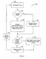
- Figure 5 is a flowchart illustrating emulation of an induction motor using an ECM.
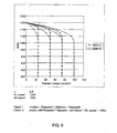
- Figure 6 is a chart illustrating an induction motor speed-torque curve that is programmed into a memory of an ECM.
- ECM electronically commutated motor
- PSC permanent, split capacitor
- ECMs electronically commutated motor
- a brushless DC motor e.g., a brushless DC motor
- reference character 11 generally designates an integrated electronically commutated motor and control circuit assembly.
- Motor assembly 11 comprises: a brushless electronically commutated DC motor 13 having a stationary assembly 15 including a stator or core 17 and a rotatable assembly 19 including a permanent magnet rotor 12 and a shaft 14.
- a fan (not shown) or other means to be driven such as means for moving air through an air handling system engages the shaft 14.
- motor assembly 11 is for use in combination with an air handling system such as an air conditioning system including a fan for blowing air over cooling coils for supplying the cooled air to a building.
- Rotor 12 is mounted on and keyed to the shaft 14 journaled for rotation in conventional bearings 16.
- the bearings 16 are mounted in bearing supports 18 integral with a first end member 20 and a second end member 22.
- the end members 20 and 22 are substantially flat and parallel to each other.
- the end members 20 and 22 have inner facing sides 24, 25 between which the stationary assembly 15 and the rotatable assembly 19 are located.
- Each end member 20 and 22 has an outer side 26, 27 opposite its inner side 24, 25.
- second end member 22 has an aperture 23 for the shaft 14 to pass through and extend out from the outer side 26.
- the rotor 12 comprises a ferromagnetic core 28 and is rotatable within the bore of stator 17. Eight essentially identical magnetic material elements or relatively thin arcuate segments 30 of permanent magnet material, each providing a relatively constant flux field, are secured, for example, by adhesive bonding to rotor core 28. The segments 30 are magnetized to be polarized radially in relation to the rotor core 28 with adjacent segments 30 being alternately polarized as indicated. While magnets 30 on rotor 12 are illustrated for purposes of disclosure, it is contemplated that other rotors having different constructions and other magnets different in both number, construction, and flux fields may be utilized with such other rotors within the scope of the invention so as to meet at least some of the objects thereof.
- Stationary assembly 15 comprises a plurality of winding stages 32 adapted to be electrically energized to generate an electromagnetic field. Stages 32 are coils of wire wound around teeth 34 of the laminated stator core 17.
- the core 17 may be held together by four retainer clips 36, one positioned within each notch 38 in the outer surface of the core 17. Alternatively, the core 17 may be held together by other suitable means, such as for instance welding or adhesively bonding, or merely held together by the windings, all as will be understood by those skilled in the art.
- the winding end turns extend beyond the stator end faces and winding terminal leads 40 are brought out through an aperture 41 in the first end member 20 terminating in a connector 42. While stationary assembly 15 is illustrated for purposes of disclosure, it is contemplated that other stationary assemblies of various other constructions having different shapes and with different number of teeth may be utilized within the scope of the invention so as to meet at least some of the objects thereof.
- Motor assembly 11 further includes a cap 44 which is mounted on the rear portion of the motor assembly 11 to enclose within the cap 44 control means 46 for the motor 13.
- the cap 44 includes an edge 48 having a plurality of spacing elements 50 projecting therefrom which engage the outer side 27 of the first end member 20.
- Cap 44 includes a substantially annular side wall 49 with the top of the side wall 49 forming edge 48.
- the control means 46 is positioned adjacent the outer side 27 of the first end member 20.
- the control means 46 includes a plurality of electronic components 52 and a connector (not shown) mounted on a component board 56, such as a printed circuit board.
- the control means 46 is connected to the winding stages 32 by interconnecting connector 42 and connector 54.
- the control means 46 applies a voltage to one or more of the winding stages 32 at a time for commutating the winding stages 32 in a preselected sequence to rotate the rotatable assembly 19 about an axis of rotation.
- Connecting elements 58 comprising a plurality of bolts pass through bolt holes 60 in the second end member 22, bolt holes 61 in core 17, bolt holes 63 in first end member 20, and bolt holes 65 in cap 44.
- the head 67 of the connecting elements 58 engage the second end member 22.
- the connecting elements 58 are adapted to urge the second end member 22 and the cap 44 toward each other thereby supporting the first end member 20, the stationary assembly 15, and the rotatable assembly 19 therebetween.
- a housing 62 may be positioned between the first end member 20 and the second end member 22 for enclosing and protecting the stationary assembly 15 and the rotatable assembly 10.
- Electronically commutated motor 13 as described herein merely for purposes of disclosure is an eight rotor-pole motor, but it will be understood that the electronically commutated motor of this invention may include any even number of rotor poles and the number of stator poles are a multiple of the number of rotor poles, for example, the number of stator poles may be based on the number of phases.
- a three-phase ECM includes six rotor pole pairs and 18 stator poles.
- the motor assembly 11 operates in the following manner.
- the winding stages 32 are energized in a temporal sequence three sets of eight magnetic poles are established that will provide a radial magnetic field which moves clockwise or counterclockwise around the core 17 depending on the preselected sequence or order in which the stages are energized.
- This moving field intersects with the flux field of the magnet 30 poles to cause the rotor to rotate relative to the core 17 in the desired direction to develop a torque which is a direct function of the intensities or strengths of the magnetic fields.
- the winding stages 32 are commutated without brushes by sensing the rotational position of the rotatable assembly 19 as it rotates within the core 17 and utilizing electrical signals generated as a function of the rotational position of the rotor 12 sequentially to apply a DC voltage to each of the winding stages 32 in different preselected orders or sequences that determine the direction of the rotation of the rotor 12.
- Position sensing may be accomplished by a position-detecting circuit responsive to the back electromotive force (EMF) to provide a simulated signal indicative of the rotational position of the rotor 12 to control the timed sequential application of voltage to the winding stages 32 of the motor 13. Other means of position sensing may also be used.
- EMF back electromotive force
- FIG. 2 illustrates the fully assembled motor assembly 11.
- Connecting elements 58 pass through the second end member 22, the stationary assembly 15, the first end member 20, and the cap 44.
- the connecting elements 58 have a portion 64 which projects laterally from the cap 44. Portion 64 is adapted to engage a support structure (not shown) for supporting the motor assembly 11.
- the connecting elements 58 may be secured in place by placing a nut 66 engaging the threads on each of the portions 64 of the connecting elements 58.
- a wiring harness 80 and connector 82 are utilized to connect motor assembly 11 to an electrical power source.
- Spacing elements 50 when engageable with the outer side 27 of the first end member 20 form air gaps 68 between the spacing elements 50, the edge 48, and the outer side 27.
- the air gaps 68 permit flow through the cap 44 thereby dissipating heat generated by the motor assembly 11. Additionally, if the motor assembly 11 is exposed to rain the air gaps 68 permit rain which has entered the cap 44 to flow out of the cap 44 via the air gaps 68.
- Indentations 75 are formed in a bottom 76 of the cap 44 which provide a space for a tool (not shown) to fit in to tighten the nuts 66.
- the indentations 75 also allow the nuts 66 to be mounted on the connecting elements 58 flush with the bottom 76 of the cap 44.
- FIG 3 is an exploded end view of an alternative embodiment for an ECM 100.
- Motor 100 includes a motor enclosure 102 and a motor control unit 104 configured for attachment to motor enclosure 102.
- a chassis 105 of motor control unit 104 serves as an end shield 106 for motor 100.
- Motor enclosure 102 also includes a slot 108 which engages a heat sink 109 formed in chassis 105 as further described below.
- motor control unit 104 includes chassis 105
- motor 100 is configured such that motor enclosure 102 provides substantially all of the enclosure for motor control unit 104.
- Within motor enclosure 102 are windings 110 of motor 100 and a mid shield 112 configured for placement between windings 110 and motor control unit 104.
- mid shield 112 allows motor control unit 104 of motor 100 to be removed and replaced without disruption or displacement of a motor winding assembly 124 which includes windings 110 of motor 100.
- motor enclosure 102 is configured to form a part of the enclosure for motor control unit 104, along with end shield 106, allowing for a one-piece enclosure configuration.
- Mid shield 112 is also configured to meet any airflow, voltage clearances and assembly height limitations imposed on motor 100.
- mid shield 112 fits precisely with respect to a centerline 125 of motor 100 and further aligns with two bolts 126 that pass through end shield 106 of motor control unit 104 to clamp and secure mid shield 112 and motor control unit 104 within motor enclosure 102.
- This alignment and symmetry remain even when chassis 105 containing the electronics of motor control unit 104 is removed. Retaining the alignment and symmetry within enclosure 102 is important as it lowers a replacement cost of motor control unit 104 in the field.
- Mid shield 112 also contributes to a lower material cost for motor 100, because with mid shield 112, motor enclosure 102 is utilized as a part of the containment enclosure for portions of motor control unit 104 as shown in Figure 3, decreasing the size of motor 100 as compared to motor 11 (shown in Figures 1 and 2). Additionally, such a configuration allows for a placement of a power connector 128 that is flush with chassis 102.
- mid shield 112 allows motor control unit 104 to be removed from enclosure 102 without disturbing the rest of the motor assembly, for example, windings 110.
- the non-disturbance is obtained by using mid shield 112 to secure a bearing that engages a motor shaft (neither shown in Figure 1) of motor 100. Therefore, enclosure 102 is additionally configured to provide any required clearances for the electrical components (e.g., motor control unit 104) of motor 100 to allow disengagement of motor control unit 104 from motor 100.
- FIG. 4 is a simplified block diagram of an ECM control circuit 130 that includes a processor 132 and power switching circuits 134.
- an ECM is powered utilizing an AC voltage 136 that is rectified by a rectifier 138 to provide a high voltage DC source 140 to power the windings of an ECM.
- a DC/DC converter 142 is utilized to provide an operating voltage 144 for processor 132 and power switching circuits 134.
- Isolation devices 146 are utilized to electrically isolate processor 132 from external devices while allowing communications to and from the external devices.
- processor 132 is programmed to operate power switching circuits 134 to selectively connect (and disconnect) windings 152, 154, and 156 of the ECM to the high voltage DC source 140 to cause a rotation of a rotor of the ECM.
- ECM control circuit 130 is configured to include one or more circuits for determining a speed and torque associated with operation of the ECM.
- circuitry of ECM control circuit 130 is configured according to the user's requirements.
- the circuitry may be configured as any of the following non-exclusive circuits alone or in combination, for example, a power supply regulating circuit, an electromagnetic interference filter, an electronically commutated motor speed modulator, an electronically commutated motor torque modulator, a transient suppression circuit, an active power factor correction circuit, a passive power factor correction circuit and a process parameter control circuit.
- a power supply regulating circuit for example, an electromagnetic interference filter, an electronically commutated motor speed modulator, an electronically commutated motor torque modulator, a transient suppression circuit, an active power factor correction circuit, a passive power factor correction circuit and a process parameter control circuit.
- the ECM assemblies described with respect to of Figures 1-4 is configured to provide high speed performance similar to an induction motor, such that the impact on system performance where the induction motor is replaced with an ECM is minimized.
- ECM control circuit 130 includes an ECM speed modulator, and an ECM motor torque modulator.
- key characteristic points of the induction motor curve are stored in the ECM memory. These characteristic points typically include breakdown speed, no load (or synchronous) speed, and a shape description number that controls tile shape of the curve between the breakdown speed and the no load speed.
- the torque is scaled by a factor less than one, that is calculated using breakdown speed, no load speed and the shape description number, which is sometimes referred to herein as "n".
- the allowed rate of change of the motor torque is reduced, in one embodiment, stepped, in order to guarantee dynamic stability.
- FIG. 5 is a flowchart 200 illustrating one method for emulating induction motor operation utilizing an ECM. Specifically, the method includes receiving 202 a desired operating torque at the ECM control circuit 130, and then accessing induction motor operating characteristics stored within the ECM control circuit. It is then determined 204, if the ECM operating speed is greater than the induction motor breakdown speed. A new torque demand is calculated 206 if a speed associated with the desired operating torque is greater than a breakdown speed of the induction motor, and a demand torque for the motor is set 208 to be substantially equal to the desired operating torque for the motor if the speed associated with the desired operating torque is less than the breakdown speed of the motor. It is then determined 210 if the output torque is substantially equal to the torque demand.
- the output torque is moved 212 toward the demanded torque if not substantially equal, and the motor is operated 214 at the output torque.
- the output torque is moved 212 toward the demanded torque by slowly stepping the output torque toward the demanded torque, to ensure dynamic stability in the operation of the ECM.
- the motor is operated 214 at the output torque if the output torque and demanded torque are substantially equal.
- the steps are then repeated 216 at the next available processing cycle of the ECM control circuit 130.
- the new torque demand is calculated 206 based on one or both of the desired operating torque and as a function of at least one of desired operating torque, motor operating speed, induction motor breakdown speed, induction motor no load speed, and an exponential value n.
- a new torque demand may be calculated according to: Desired operating torque ⁇ 1 - i . m . operating speed - i . m . breakdown speed n i . m . noload speed - i . m . breakdown speed n where n is a real number stored in a memory of the ECM and i.m. means "induction motor".
- induction motor breakdown speed is replaced with: i . m . noload speed - per unit torque demand ⁇ ( i . m . noload speed - i . m . breakdown speed ) .
- Figure 6 is a chart 250 illustrating a specific embodiment of an induction motor speed-torque curve.
- Chart 250 is illustrative of key characteristic points of an induction motor speed-torque curve that might be stored, for example, within a memory of an ECM control circuit. These key characteristic points include, for example, breakdown speed, noload or synchronous speed, and a shape description number that controls the shape of the curve between the two speeds. In one embodiment, this shape description number is the "n" referred to above.
- the torque is scaled by a factor less than one, that is calculated by the formula above using the shape description number, the breakdown speed, and the noload speed. At the same time, the allowed rate of change of the motor torque is reduced, in order to guarantee dynamic stability.
- an ECM can be constrained to operate with characteristics similar to the operating characteristics of an induction motor, then at least some of the re-rating activity described above with respect to the replacement of an induction motor with an ECM can be eliminated.
Landscapes
- Engineering & Computer Science (AREA)
- Mechanical Engineering (AREA)
- General Engineering & Computer Science (AREA)
- Power Engineering (AREA)
- Control Of Motors That Do Not Use Commutators (AREA)
- Control Of Ac Motors In General (AREA)
Applications Claiming Priority (1)
| Application Number | Priority Date | Filing Date | Title |
|---|---|---|---|
| US11/365,062 US7436138B2 (en) | 2006-03-01 | 2006-03-01 | Methods and systems for emulating an induction motor utilizing an electronically commutated motor |
Publications (3)
| Publication Number | Publication Date |
|---|---|
| EP1830462A2 true EP1830462A2 (fr) | 2007-09-05 |
| EP1830462A3 EP1830462A3 (fr) | 2010-07-07 |
| EP1830462B1 EP1830462B1 (fr) | 2017-08-16 |
Family
ID=37982453
Family Applications (1)
| Application Number | Title | Priority Date | Filing Date |
|---|---|---|---|
| EP07250857.5A Not-in-force EP1830462B1 (fr) | 2006-03-01 | 2007-03-01 | Procédés et systèmes d'émulation d'un moteur à induction utilisant un moteur à commutation électronique |
Country Status (4)
| Country | Link |
|---|---|
| US (1) | US7436138B2 (fr) |
| EP (1) | EP1830462B1 (fr) |
| CA (1) | CA2575888C (fr) |
| MX (1) | MX2007002550A (fr) |
Cited By (1)
| Publication number | Priority date | Publication date | Assignee | Title |
|---|---|---|---|---|
| EP2624438A1 (fr) * | 2012-02-04 | 2013-08-07 | Andreas Stihl AG & Co. KG | Procédé de fonctionnement d'un appareil de travail avec un moteur électrique et appareil de travail avec un moteur électrique |
Families Citing this family (17)
| Publication number | Priority date | Publication date | Assignee | Title |
|---|---|---|---|---|
| US20080030088A1 (en) * | 2006-07-18 | 2008-02-07 | Daniel Gizaw | Compact integrated brushless permanent-magnet motor & drive |
| FI121613B (fi) * | 2006-12-21 | 2011-01-31 | Abb Oy | Menetelmä ja järjestelmä jännitevälipiirisellä taajuusmuuttajalla syötetyn moottorin yhteydessä |
| US8288975B2 (en) * | 2007-01-26 | 2012-10-16 | Regal Beloit Epc Inc. | BLDC motor with a simulated tapped winding interface |
| US20100052457A1 (en) * | 2008-08-29 | 2010-03-04 | Brahmavar Subhash M | Methods and apparatus for fabrication of electric motors |
| CN103201945A (zh) * | 2010-11-10 | 2013-07-10 | 惠灵顿驱动科技有限公司 | 可编程电机和方法 |
| JP5692575B2 (ja) | 2010-12-28 | 2015-04-01 | 株式会社デンソー | 駆動装置 |
| JP5692588B2 (ja) | 2010-12-28 | 2015-04-01 | 株式会社デンソー | 駆動装置 |
| US9667188B2 (en) * | 2011-04-05 | 2017-05-30 | Belimo Holding Ag | Flow control actuator |
| US8896248B2 (en) * | 2011-07-27 | 2014-11-25 | Regal Beloit America, Inc. | Methods and systems for controlling a motor |
| US9529038B2 (en) * | 2011-11-21 | 2016-12-27 | Ebm-Papst Mulfingen Gmbh & Co. Kg | Electronic control circuit comprising power transistors and method for monitoring the service life of the power transistors |
| DE102012002225B4 (de) | 2012-02-04 | 2025-09-04 | Andreas Stihl Ag & Co. Kg | Handgeführtes Arbeitsgerät |
| EP2949027A4 (fr) * | 2013-01-28 | 2016-11-09 | Dixon Pumps Inc | Système, appareil et procédé pour commander un moteur |
| GB2513193B (en) * | 2013-04-19 | 2015-06-03 | Dyson Technology Ltd | Air moving appliance with on-board diagnostics |
| CN103671199B (zh) * | 2013-12-26 | 2016-04-20 | 中冶长天国际工程有限责任公司 | 风机变频调速方法及系统 |
| CN105024593B (zh) * | 2014-04-30 | 2018-04-06 | 中山大洋电机股份有限公司 | 一种hvac系统 |
| US10333448B2 (en) * | 2017-04-10 | 2019-06-25 | GM Global Technology Operations LLC | Method for torque control systems and methods based on rotor temperature |
| US10736233B1 (en) * | 2019-04-25 | 2020-08-04 | The Boeing Company | Self-contained cooling device for an electromagnetic interference filter |
Family Cites Families (21)
| Publication number | Priority date | Publication date | Assignee | Title |
|---|---|---|---|---|
| DE2804561A1 (de) | 1978-02-03 | 1979-08-09 | Papst Motoren Kg | Zweipulsiger kollektorloser gleichstrommotor |
| US4500821A (en) | 1983-06-09 | 1985-02-19 | General Electric Company | Speed or torque control circuit for an electronically commutated motor (ECM) and method of controlling the torque or speed of an ECM |
| US5006744A (en) * | 1988-12-27 | 1991-04-09 | General Electric Company | Integrated electronically commutated motor and control circuit assembly |
| US5510689A (en) * | 1990-10-01 | 1996-04-23 | Wisconsin Alumni Research Foundation | Air gap flux measurement using stator third harmonic voltage |
| US6348752B1 (en) | 1992-04-06 | 2002-02-19 | General Electric Company | Integral motor and control |
| US5592058A (en) * | 1992-05-27 | 1997-01-07 | General Electric Company | Control system and methods for a multiparameter electronically commutated motor |
| USRE37576E1 (en) | 1993-02-22 | 2002-03-12 | General Electric Company | Single phase motor with positive torque parking positions |
| US6768279B1 (en) * | 1994-05-27 | 2004-07-27 | Emerson Electric Co. | Reprogrammable motor drive and control therefore |
| US6262510B1 (en) | 1994-09-22 | 2001-07-17 | Iancu Lungu | Electronically switched reluctance motor |
| JP3584106B2 (ja) * | 1996-01-26 | 2004-11-04 | セイコーエプソン株式会社 | 電気自動車の駆動装置及びその制御方法 |
| US5818194A (en) * | 1996-04-01 | 1998-10-06 | Emerson Electric Co. | Direct replacement variable speed blower motor |
| US6369536B2 (en) | 1999-12-27 | 2002-04-09 | General Electric Company | Methods and apparatus for selecting an electronically commutated motor speed |
| US6992403B1 (en) | 2001-03-08 | 2006-01-31 | Pacific Scientific | Electric power and start system |
| US6369535B1 (en) | 2001-07-31 | 2002-04-09 | General Electric Company | Method and apparatus for current shaping in electronically commutated motors |
| US6456023B1 (en) | 2001-08-08 | 2002-09-24 | General Electric Company | Method and apparatus to control a variable speed motor |
| US6465977B1 (en) * | 2001-11-29 | 2002-10-15 | Ecostar Electric Drive Systems L.L.C. | System and method for controlling torque in an electrical machine |
| US20030223738A1 (en) | 2002-05-30 | 2003-12-04 | Hughes Ronald Wayne | Method and system for solid state DC crane control |
| US6895176B2 (en) * | 2002-09-12 | 2005-05-17 | General Electric Company | Method and apparatus for controlling electronically commutated motor operating characteristics |
| US6853159B2 (en) | 2003-06-30 | 2005-02-08 | Valeo Elctrical Systems, Inc. | Apparatus and method for generating torque |
| US7002311B2 (en) * | 2004-03-18 | 2006-02-21 | Minebea Co., Ltd. | Motor speed sensor advancement emulation and compensation |
| US20060043916A1 (en) | 2004-09-01 | 2006-03-02 | The Consortium, Llc | Motor system having multiple motor torque constants |
-
2006
- 2006-03-01 US US11/365,062 patent/US7436138B2/en active Active
-
2007
- 2007-01-26 CA CA2575888A patent/CA2575888C/fr not_active Expired - Fee Related
- 2007-03-01 MX MX2007002550A patent/MX2007002550A/es active IP Right Grant
- 2007-03-01 EP EP07250857.5A patent/EP1830462B1/fr not_active Not-in-force
Non-Patent Citations (1)
| Title |
|---|
| None |
Cited By (3)
| Publication number | Priority date | Publication date | Assignee | Title |
|---|---|---|---|---|
| EP2624438A1 (fr) * | 2012-02-04 | 2013-08-07 | Andreas Stihl AG & Co. KG | Procédé de fonctionnement d'un appareil de travail avec un moteur électrique et appareil de travail avec un moteur électrique |
| CN103248299A (zh) * | 2012-02-04 | 2013-08-14 | 安德烈亚斯.斯蒂尔两合公司 | 用于使电动马达运行的方法以及带有电动马达的工作器械 |
| CN103248299B (zh) * | 2012-02-04 | 2017-04-12 | 安德烈亚斯.斯蒂尔两合公司 | 用于使电动马达运行的方法以及带有电动马达的工作器械 |
Also Published As
| Publication number | Publication date |
|---|---|
| CA2575888C (fr) | 2015-10-20 |
| US7436138B2 (en) | 2008-10-14 |
| MX2007002550A (es) | 2008-11-14 |
| EP1830462B1 (fr) | 2017-08-16 |
| US20070205732A1 (en) | 2007-09-06 |
| CA2575888A1 (fr) | 2007-09-01 |
| EP1830462A3 (fr) | 2010-07-07 |
Similar Documents
| Publication | Publication Date | Title |
|---|---|---|
| CA2575888C (fr) | Methodes et systemes pour emuler un moteur a induction utilisant un moteur commute electroniquement | |
| US9013074B2 (en) | Resilient rotor assembly for interior permanent magnet motor | |
| AU2007221923B2 (en) | Methods and systems for operating direct current motors | |
| CN101237208B (zh) | 低噪声的加热、通风和/或空气调节(hvac)系统 | |
| US7812564B2 (en) | Blower and electric device with such blower mounted thereon | |
| EP2159582B1 (fr) | Procédés et appareil pour la surveillance du courant moyen et de l'alimentation d'entrée d'un moteur commuté électroniquement | |
| US8896248B2 (en) | Methods and systems for controlling a motor | |
| MX2007002553A (es) | Métodos y sistemas para frenar dinámicamente un motor conmutado electrónicamente. | |
| CN104426440A (zh) | 控制电机的方法 | |
| US20100052457A1 (en) | Methods and apparatus for fabrication of electric motors | |
| Singh | Recent advances in permanent magnet brushless DC motors | |
| JP2006149048A (ja) | 交流電源直結型ブラシレスdcモータおよびそれを搭載した電気機器 | |
| JP3901146B2 (ja) | 交流電源直結型ブラシレスdcモータおよびそれを搭載した電気機器 | |
| JP3699081B2 (ja) | 交流電源直結型ブラシレスdcモータおよびそれを搭載した電気機器 | |
| JP3770239B2 (ja) | 交流電源直結型ブラシレスdcモータおよびそれを搭載した電気機器 | |
| JP3901157B2 (ja) | 交流電源直結型ブラシレスdcモータおよびそれを搭載した電気機器 | |
| US20170110942A1 (en) | Induction motor and method of manufacture | |
| CN222192174U (zh) | 一种应用三相爪极步进电机的汽车执行器系统 | |
| JP2005176474A (ja) | 交流電源直結型ブラシレスdcモータおよびそれを搭載した電気機器 | |
| JP2670022B2 (ja) | 無整流子電動機 | |
| JP2670023B2 (ja) | ファンモータ用の無整流子電動機 | |
| JP3814627B2 (ja) | 交流電源直結型ブラシレスdcモータおよびそれを搭載した電気機器 | |
| JP2003079116A (ja) | モータ | |
| CN112436682A (zh) | 电机组件、送风装置、家用电器和电动车辆 | |
| JPS62163592A (ja) | 直流無刷子電動機 |
Legal Events
| Date | Code | Title | Description |
|---|---|---|---|
| PUAI | Public reference made under article 153(3) epc to a published international application that has entered the european phase |
Free format text: ORIGINAL CODE: 0009012 |
|
| AK | Designated contracting states |
Kind code of ref document: A2 Designated state(s): AT BE BG CH CY CZ DE DK EE ES FI FR GB GR HU IE IS IT LI LT LU LV MC MT NL PL PT RO SE SI SK TR |
|
| AX | Request for extension of the european patent |
Extension state: AL BA HR MK YU |
|
| PUAL | Search report despatched |
Free format text: ORIGINAL CODE: 0009013 |
|
| AK | Designated contracting states |
Kind code of ref document: A3 Designated state(s): AT BE BG CH CY CZ DE DK EE ES FI FR GB GR HU IE IS IT LI LT LU LV MC MT NL PL PT RO SE SI SK TR |
|
| AX | Request for extension of the european patent |
Extension state: AL BA HR MK RS |
|
| 17P | Request for examination filed |
Effective date: 20110106 |
|
| AKX | Designation fees paid |
Designated state(s): AT BE BG CH CY CZ DE DK EE ES FI FR GB GR HU IE IS IT LI LT LU LV MC MT NL PL PT RO SE SI SK TR |
|
| 17Q | First examination report despatched |
Effective date: 20110623 |
|
| REG | Reference to a national code |
Ref country code: DE Ref legal event code: R079 Ref document number: 602007051994 Country of ref document: DE Free format text: PREVIOUS MAIN CLASS: H02P0006000000 Ipc: H02P0006340000 |
|
| GRAP | Despatch of communication of intention to grant a patent |
Free format text: ORIGINAL CODE: EPIDOSNIGR1 |
|
| STAA | Information on the status of an ep patent application or granted ep patent |
Free format text: STATUS: GRANT OF PATENT IS INTENDED |
|
| RIC1 | Information provided on ipc code assigned before grant |
Ipc: F04D 27/00 20060101ALI20170126BHEP Ipc: H02P 6/34 20160101AFI20170126BHEP |
|
| INTG | Intention to grant announced |
Effective date: 20170227 |
|
| GRAS | Grant fee paid |
Free format text: ORIGINAL CODE: EPIDOSNIGR3 |
|
| GRAA | (expected) grant |
Free format text: ORIGINAL CODE: 0009210 |
|
| STAA | Information on the status of an ep patent application or granted ep patent |
Free format text: STATUS: THE PATENT HAS BEEN GRANTED |
|
| AK | Designated contracting states |
Kind code of ref document: B1 Designated state(s): AT BE BG CH CY CZ DE DK EE ES FI FR GB GR HU IE IS IT LI LT LU LV MC MT NL PL PT RO SE SI SK TR |
|
| REG | Reference to a national code |
Ref country code: GB Ref legal event code: FG4D |
|
| REG | Reference to a national code |
Ref country code: CH Ref legal event code: EP |
|
| REG | Reference to a national code |
Ref country code: IE Ref legal event code: FG4D |
|
| REG | Reference to a national code |
Ref country code: AT Ref legal event code: REF Ref document number: 919996 Country of ref document: AT Kind code of ref document: T Effective date: 20170915 |
|
| REG | Reference to a national code |
Ref country code: DE Ref legal event code: R096 Ref document number: 602007051994 Country of ref document: DE |
|
| REG | Reference to a national code |
Ref country code: NL Ref legal event code: MP Effective date: 20170816 |
|
| REG | Reference to a national code |
Ref country code: LT Ref legal event code: MG4D |
|
| REG | Reference to a national code |
Ref country code: AT Ref legal event code: MK05 Ref document number: 919996 Country of ref document: AT Kind code of ref document: T Effective date: 20170816 |
|
| PG25 | Lapsed in a contracting state [announced via postgrant information from national office to epo] |
Ref country code: FI Free format text: LAPSE BECAUSE OF FAILURE TO SUBMIT A TRANSLATION OF THE DESCRIPTION OR TO PAY THE FEE WITHIN THE PRESCRIBED TIME-LIMIT Effective date: 20170816 Ref country code: NL Free format text: LAPSE BECAUSE OF FAILURE TO SUBMIT A TRANSLATION OF THE DESCRIPTION OR TO PAY THE FEE WITHIN THE PRESCRIBED TIME-LIMIT Effective date: 20170816 Ref country code: AT Free format text: LAPSE BECAUSE OF FAILURE TO SUBMIT A TRANSLATION OF THE DESCRIPTION OR TO PAY THE FEE WITHIN THE PRESCRIBED TIME-LIMIT Effective date: 20170816 Ref country code: SE Free format text: LAPSE BECAUSE OF FAILURE TO SUBMIT A TRANSLATION OF THE DESCRIPTION OR TO PAY THE FEE WITHIN THE PRESCRIBED TIME-LIMIT Effective date: 20170816 Ref country code: LT Free format text: LAPSE BECAUSE OF FAILURE TO SUBMIT A TRANSLATION OF THE DESCRIPTION OR TO PAY THE FEE WITHIN THE PRESCRIBED TIME-LIMIT Effective date: 20170816 |
|
| PG25 | Lapsed in a contracting state [announced via postgrant information from national office to epo] |
Ref country code: GR Free format text: LAPSE BECAUSE OF FAILURE TO SUBMIT A TRANSLATION OF THE DESCRIPTION OR TO PAY THE FEE WITHIN THE PRESCRIBED TIME-LIMIT Effective date: 20171117 Ref country code: IS Free format text: LAPSE BECAUSE OF FAILURE TO SUBMIT A TRANSLATION OF THE DESCRIPTION OR TO PAY THE FEE WITHIN THE PRESCRIBED TIME-LIMIT Effective date: 20171216 Ref country code: ES Free format text: LAPSE BECAUSE OF FAILURE TO SUBMIT A TRANSLATION OF THE DESCRIPTION OR TO PAY THE FEE WITHIN THE PRESCRIBED TIME-LIMIT Effective date: 20170816 Ref country code: LV Free format text: LAPSE BECAUSE OF FAILURE TO SUBMIT A TRANSLATION OF THE DESCRIPTION OR TO PAY THE FEE WITHIN THE PRESCRIBED TIME-LIMIT Effective date: 20170816 Ref country code: BG Free format text: LAPSE BECAUSE OF FAILURE TO SUBMIT A TRANSLATION OF THE DESCRIPTION OR TO PAY THE FEE WITHIN THE PRESCRIBED TIME-LIMIT Effective date: 20171116 Ref country code: PL Free format text: LAPSE BECAUSE OF FAILURE TO SUBMIT A TRANSLATION OF THE DESCRIPTION OR TO PAY THE FEE WITHIN THE PRESCRIBED TIME-LIMIT Effective date: 20170816 |
|
| PG25 | Lapsed in a contracting state [announced via postgrant information from national office to epo] |
Ref country code: CZ Free format text: LAPSE BECAUSE OF FAILURE TO SUBMIT A TRANSLATION OF THE DESCRIPTION OR TO PAY THE FEE WITHIN THE PRESCRIBED TIME-LIMIT Effective date: 20170816 Ref country code: RO Free format text: LAPSE BECAUSE OF FAILURE TO SUBMIT A TRANSLATION OF THE DESCRIPTION OR TO PAY THE FEE WITHIN THE PRESCRIBED TIME-LIMIT Effective date: 20170816 Ref country code: DK Free format text: LAPSE BECAUSE OF FAILURE TO SUBMIT A TRANSLATION OF THE DESCRIPTION OR TO PAY THE FEE WITHIN THE PRESCRIBED TIME-LIMIT Effective date: 20170816 |
|
| REG | Reference to a national code |
Ref country code: DE Ref legal event code: R097 Ref document number: 602007051994 Country of ref document: DE |
|
| PG25 | Lapsed in a contracting state [announced via postgrant information from national office to epo] |
Ref country code: IT Free format text: LAPSE BECAUSE OF FAILURE TO SUBMIT A TRANSLATION OF THE DESCRIPTION OR TO PAY THE FEE WITHIN THE PRESCRIBED TIME-LIMIT Effective date: 20170816 Ref country code: EE Free format text: LAPSE BECAUSE OF FAILURE TO SUBMIT A TRANSLATION OF THE DESCRIPTION OR TO PAY THE FEE WITHIN THE PRESCRIBED TIME-LIMIT Effective date: 20170816 Ref country code: SK Free format text: LAPSE BECAUSE OF FAILURE TO SUBMIT A TRANSLATION OF THE DESCRIPTION OR TO PAY THE FEE WITHIN THE PRESCRIBED TIME-LIMIT Effective date: 20170816 |
|
| PLBE | No opposition filed within time limit |
Free format text: ORIGINAL CODE: 0009261 |
|
| STAA | Information on the status of an ep patent application or granted ep patent |
Free format text: STATUS: NO OPPOSITION FILED WITHIN TIME LIMIT |
|
| 26N | No opposition filed |
Effective date: 20180517 |
|
| PG25 | Lapsed in a contracting state [announced via postgrant information from national office to epo] |
Ref country code: SI Free format text: LAPSE BECAUSE OF FAILURE TO SUBMIT A TRANSLATION OF THE DESCRIPTION OR TO PAY THE FEE WITHIN THE PRESCRIBED TIME-LIMIT Effective date: 20170816 |
|
| REG | Reference to a national code |
Ref country code: CH Ref legal event code: PL |
|
| GBPC | Gb: european patent ceased through non-payment of renewal fee |
Effective date: 20180301 |
|
| PG25 | Lapsed in a contracting state [announced via postgrant information from national office to epo] |
Ref country code: MC Free format text: LAPSE BECAUSE OF FAILURE TO SUBMIT A TRANSLATION OF THE DESCRIPTION OR TO PAY THE FEE WITHIN THE PRESCRIBED TIME-LIMIT Effective date: 20170816 |
|
| REG | Reference to a national code |
Ref country code: BE Ref legal event code: MM Effective date: 20180331 |
|
| REG | Reference to a national code |
Ref country code: IE Ref legal event code: MM4A |
|
| PG25 | Lapsed in a contracting state [announced via postgrant information from national office to epo] |
Ref country code: LU Free format text: LAPSE BECAUSE OF NON-PAYMENT OF DUE FEES Effective date: 20180301 |
|
| PG25 | Lapsed in a contracting state [announced via postgrant information from national office to epo] |
Ref country code: IE Free format text: LAPSE BECAUSE OF NON-PAYMENT OF DUE FEES Effective date: 20180301 |
|
| PG25 | Lapsed in a contracting state [announced via postgrant information from national office to epo] |
Ref country code: GB Free format text: LAPSE BECAUSE OF NON-PAYMENT OF DUE FEES Effective date: 20180301 Ref country code: LI Free format text: LAPSE BECAUSE OF NON-PAYMENT OF DUE FEES Effective date: 20180331 Ref country code: CH Free format text: LAPSE BECAUSE OF NON-PAYMENT OF DUE FEES Effective date: 20180331 Ref country code: BE Free format text: LAPSE BECAUSE OF NON-PAYMENT OF DUE FEES Effective date: 20180331 |
|
| PG25 | Lapsed in a contracting state [announced via postgrant information from national office to epo] |
Ref country code: FR Free format text: LAPSE BECAUSE OF NON-PAYMENT OF DUE FEES Effective date: 20180331 |
|
| PG25 | Lapsed in a contracting state [announced via postgrant information from national office to epo] |
Ref country code: MT Free format text: LAPSE BECAUSE OF NON-PAYMENT OF DUE FEES Effective date: 20180301 |
|
| PG25 | Lapsed in a contracting state [announced via postgrant information from national office to epo] |
Ref country code: TR Free format text: LAPSE BECAUSE OF FAILURE TO SUBMIT A TRANSLATION OF THE DESCRIPTION OR TO PAY THE FEE WITHIN THE PRESCRIBED TIME-LIMIT Effective date: 20170816 |
|
| PGFP | Annual fee paid to national office [announced via postgrant information from national office to epo] |
Ref country code: DE Payment date: 20200327 Year of fee payment: 14 |
|
| PG25 | Lapsed in a contracting state [announced via postgrant information from national office to epo] |
Ref country code: PT Free format text: LAPSE BECAUSE OF FAILURE TO SUBMIT A TRANSLATION OF THE DESCRIPTION OR TO PAY THE FEE WITHIN THE PRESCRIBED TIME-LIMIT Effective date: 20170816 Ref country code: HU Free format text: LAPSE BECAUSE OF FAILURE TO SUBMIT A TRANSLATION OF THE DESCRIPTION OR TO PAY THE FEE WITHIN THE PRESCRIBED TIME-LIMIT; INVALID AB INITIO Effective date: 20070301 |
|
| PG25 | Lapsed in a contracting state [announced via postgrant information from national office to epo] |
Ref country code: CY Free format text: LAPSE BECAUSE OF FAILURE TO SUBMIT A TRANSLATION OF THE DESCRIPTION OR TO PAY THE FEE WITHIN THE PRESCRIBED TIME-LIMIT Effective date: 20170816 |
|
| REG | Reference to a national code |
Ref country code: DE Ref legal event code: R119 Ref document number: 602007051994 Country of ref document: DE |
|
| PG25 | Lapsed in a contracting state [announced via postgrant information from national office to epo] |
Ref country code: DE Free format text: LAPSE BECAUSE OF NON-PAYMENT OF DUE FEES Effective date: 20211001 |