EP1831023B1 - Outil permettant de retirer d'une imprimante a jet d'encre un conteneur servant a alimenter cette derniere en fluide - Google Patents
Outil permettant de retirer d'une imprimante a jet d'encre un conteneur servant a alimenter cette derniere en fluide Download PDFInfo
- Publication number
- EP1831023B1 EP1831023B1 EP05803489A EP05803489A EP1831023B1 EP 1831023 B1 EP1831023 B1 EP 1831023B1 EP 05803489 A EP05803489 A EP 05803489A EP 05803489 A EP05803489 A EP 05803489A EP 1831023 B1 EP1831023 B1 EP 1831023B1
- Authority
- EP
- European Patent Office
- Prior art keywords
- container
- tool
- printer
- ink jet
- protrusions
- Prior art date
- Legal status (The legal status is an assumption and is not a legal conclusion. Google has not performed a legal analysis and makes no representation as to the accuracy of the status listed.)
- Expired - Lifetime
Links
Images




Classifications
-
- B—PERFORMING OPERATIONS; TRANSPORTING
- B41—PRINTING; LINING MACHINES; TYPEWRITERS; STAMPS
- B41J—TYPEWRITERS; SELECTIVE PRINTING MECHANISMS, i.e. MECHANISMS PRINTING OTHERWISE THAN FROM A FORME; CORRECTION OF TYPOGRAPHICAL ERRORS
- B41J2/00—Typewriters or selective printing mechanisms characterised by the printing or marking process for which they are designed
- B41J2/005—Typewriters or selective printing mechanisms characterised by the printing or marking process for which they are designed characterised by bringing liquid or particles selectively into contact with a printing material
- B41J2/01—Ink jet
- B41J2/17—Ink jet characterised by ink handling
- B41J2/175—Ink supply systems ; Circuit parts therefor
- B41J2/17503—Ink cartridges
- B41J2/1752—Mounting within the printer
-
- Y—GENERAL TAGGING OF NEW TECHNOLOGICAL DEVELOPMENTS; GENERAL TAGGING OF CROSS-SECTIONAL TECHNOLOGIES SPANNING OVER SEVERAL SECTIONS OF THE IPC; TECHNICAL SUBJECTS COVERED BY FORMER USPC CROSS-REFERENCE ART COLLECTIONS [XRACs] AND DIGESTS
- Y10—TECHNICAL SUBJECTS COVERED BY FORMER USPC
- Y10T—TECHNICAL SUBJECTS COVERED BY FORMER US CLASSIFICATION
- Y10T29/00—Metal working
- Y10T29/53—Means to assemble or disassemble
- Y10T29/53796—Puller or pusher means, contained force multiplying operator
- Y10T29/53896—Puller or pusher means, contained force multiplying operator having lever operator
-
- Y—GENERAL TAGGING OF NEW TECHNOLOGICAL DEVELOPMENTS; GENERAL TAGGING OF CROSS-SECTIONAL TECHNOLOGIES SPANNING OVER SEVERAL SECTIONS OF THE IPC; TECHNICAL SUBJECTS COVERED BY FORMER USPC CROSS-REFERENCE ART COLLECTIONS [XRACs] AND DIGESTS
- Y10—TECHNICAL SUBJECTS COVERED BY FORMER USPC
- Y10T—TECHNICAL SUBJECTS COVERED BY FORMER US CLASSIFICATION
- Y10T29/00—Metal working
- Y10T29/53—Means to assemble or disassemble
- Y10T29/53909—Means comprising hand manipulatable tool
Definitions
- This invention relates to an ink jet printer comprising a tool for assisting the removal of a container used to supply fluid to the printer.
- US-A-6 158 854 discloses an ink jet printer including a container for supplying ink/ink solvent to the printer.
- the container supplies the ink/solvent by way of a coupling between the container and printer.
- the coupling comprises a male connector part carried by the container, and a female connector part carried by the printer.
- First and second sloped protrusions are provided on opposite sides of the opening in the female connector part. When the coupling is made the first and second sloped protrusions are received in respective first and second sloped recesses formed in the main body of the container on opposite sides of the male connector part.
- the sloped surfaces of the protrusions lie against the sloped surfaces of the recesses when the container is installed in the printer. Removal of the container and breaking of the seal between the male and female connector parts is achieved by manually rotating the container. This causes the abutting sloped surfaces to ride over one another and in doing so push the container away from the printer.
- US-A-6 158 854 has the disadvantage that the exterior of the printer must not obstruct rotation of the container to remove the container. This places a limitation on the design of the printer. Further, the manual grasping of the container to rotate it may, if not carefully done, put undue strain on the O-ring seal causing damage to the seal.
- US-B1-6 170 940 discloses an ink jet printer including an ink cartridge locking member which prevents both (i) inadvertent loading of an ink cartridge into the printer, and (ii) inadvertent removal of an ink cartridge from the printer.
- an ink jet printer installed in the printer a container for supplying fluid to the printer; and, interposed between said printer and said container, a tool for assisting the removal from the printer of the container, said tool including a raised portion which on movement of said tool from a first to a second position acts so as to push said container away from said printer, said movement from a first to a second position involving rotation of said tool in a plane between said printer and said container, which plane is generally perpendicular to the direction in which said container delivers fluid to said printer, wherein said raised portion comprises first and second sloped protrusions, said protrusions being spaced apart in said plane and disposed on opposite sides of an opening in said container for dispensing said fluid, the slope of each of the first and second sloped protrusions varying the projection from said tool of the protrusion, wherein said movement of the tool from the first to the second position pushes the container away from the printer by causing the container to engage the first and second sloped protrusions at
- the tool suitably comprises a generally planar main part and a handle for use of the tool extending from the main part, the main part including an opening which is aligned with the opening in the container, the main part also including the aforesaid protrusions which are disposed on opposite sides of the opening in the main part.
- the tool is suitably mounted on the printer.
- the printer includes a construction suitable for preventing movement of the container with the tool as the tool is moved from the aforesaid first to second positions.
- the construction suitably comprises first and second sub-constructions located on opposite sides of an opening in the printer for receiving the fluid, engagement of the container with the sub-constructions preventing the movement of the container with the tool.
- Each sub-construction suitably comprises a pair of adjacent projections defining a channel therebetween.
- the container includes first and second projections, which projections are located in respective aforesaid channels, the aforesaid movement of the tool from a first to a second position pushing the raised portion of the tool against the projections of the container to push the container away from the printer.
- a tool 1 is mounted on a top plate 3 of an ink jet printer by means of a mounting 5.
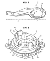
- tool 1 comprises a generally planar, annular main part 7, and a handle 9 for use of the tool extending from main part 7.
- Annular main part 7 includes first and second sloped protrusions 11 disposed on opposite sides of the opening of the annular part. Each protrusion 11 slopes from no projection from the plane of main part 7 to a maximum projection.
- mounting 5 comprises a female connector part 13 as shown in Fig. 6 , an arcuate stop member 15 as shown in Fig. 7 , and a mounting plate 17 as shown in Fig. 8 .
- Annular main part 7 of tool 1 rests on ledge 19 of female connector part 13, and encircles and abuts the exterior of wall 21 of part 13.
- Mounting plate 17 rests on the top 23 of wall 21.
- Top plate 3 of the printer rests on ledge 25 of connector part 13, and encircles and abuts wall 27 of part 13.
- Arcuate stop member 15 is disposed between mounting plate 17 and top plate 3 of the printer, and extends halfway around female connector part 13 and annular main part 7 of tool 1. Boreholes 29 at either end of arcuate member 15 align with diametrically opposite boreholes in mounting plate 17, top printer plate 3, and female connector part 13.
- the diametrically opposite boreholes in mounting plate 17 are referenced 31, and in female connector part 13 are referenced 33.
- Bolts 35 extend through the boreholes to secure the assembly together.
- Diametrically opposite first and second pairs of adjacent projections 37 protrude from top 23 of wall 21 of female connector part 13.
- Each pair of projections 37 defines therebetween a channel 39.
- Formed in mounting plate 17 is a pair of opposite arcuate slots 41, and cut into the shorter side of each arcuate slot 41 is a pair of recesses 43.
- arcuate slots 41 accommodate sloped protrusions 11 of tool 1
- recesses 43 accommodate pairs of adjacent projections 37 of female connector part 13.
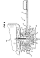
- an installed container 51 includes a male connector part 53 fitted at the fluid dispensing opening of container 51.
- Male connector part 53 comprises an outer casing 55, a valve armature 57, and a valve surround 59.
- a spring 71 surrounds armature 57.
- a neck 65 of container 51 surrounds its fluid dispensing opening.
- An O-ring 67 seals between neck 65 and outer casing 55 of male connector part 53.
- Male connector part 53 is received by female connector part 13 of mounting 5 on the printer.
- a ring seal 61 seals between male and female connector parts 53, 13. Ring seal 61 includes a lip 63 which bears against male connector part 53.
- a stub protrusion 69 at the centre of female connector part 13 (see also Fig.
- valve armature 57 engages valve armature 57 so as to push it in an upwards direction against the action of spring 71.
- first and second pairs of adjacent clips 81 are located on opposite sides of outer casing 55 of the male connector part. Disposed between the adjacent clips of each pair is a generally rectangular, planar projection 83.
- clips 81 clip onto container 51 to assist in securing male connector part 53 to the container.
- Projections 83 slot into corresponding channels 39 defined between the adjacent projections of the first and second pairs of projections 37 of female connector part 13 of mounting 5 on the printer.
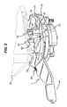
- Fig. 2 shows container 51 fully installed in the printer.
- tool 1 is positioned such that its first and second sloped protrusions 11 are located at extreme ends of arcuate slots 41 of mounting plate 17.
- sloped protrusions 11 do not - interfere with planar projections 83 of male connector part 53.
- a spring 91 biases tool 1 to its position shown in Fig. 2 .
- removal of container 51 is achieved by rotating tool 1 so as to cause sloped protrusions 11 to travel along arcuate slots 41 such that the sloped surfaces of protrusions 11 engage planar projections 83 thereby lifting projections 83.
- the projections 37 on the side of planar projections 83 remote from sloped protrusions 11 prevent rotation of container 51 and thereby facilitate lifting of the container.
- lifting of container 51 is against the resistance of ring seal 61 and causes valve armature 57 to be lifted off stub protrusion 69 thereby allowing spring 71 to close annular opening 73 preventing fluid leaving container 51.
Landscapes
- Ink Jet (AREA)
Claims (8)
- Imprimante à jet d'encre, comprenant : un récipient (51) pour amener le fluide vers l'imprimante ; et, agencé entre ladite imprimante et ledit récipient (51), un outil (1) pour faciliter le retrait du récipient (51) de l'imprimante, ledit outil (1) englobant une partie surélevée (11), entraînant, lors du déplacement dudit outil (1) d'une première position vers une deuxième position, la poussée dudit récipient (51) à l'écart de ladite imprimante, ledit déplacement d'une première position vers une deuxième position comprenant la rotation dudit outil (1) dans un plan entre ladite imprimante et ledit récipient (51), ce plan étant en généra perpendiculaire à la direction dans laquelle ledit récipient (51) distribue le fluide vers ladite imprimante, ladite partie surélevée (11) comprenant des première et deuxièmes saillies inclinées (11), lesdites saillies (11) étant espacées dans ledit plan et agencées sur les côtés opposés d'une ouverture dans ledit récipient (51), pour distribuer ledit fluide, l'inclinaison de chacune des première et deuxième saillies inclinées (11) changeant la projection de ladite saillie (11) par rapport audit outil (1), ledit déplacement de l'outil (1) de la première position vers la deuxième position poussent le récipient à l'écart de l'imprimante en entraînant l'engagement du récipient (51) dans les première et deuxième saillies inclinées (11) en présence de projections progressivement accrues des saillies (11) par rapport à l'outil (1).
- Imprimante à jet d'encre selon la revendication 1, dans laquelle ledit outil (1) comprend une partie principale généralement plane (7) et une poignée (9) en vue de l'utilisation de l'outil (1), s'étendant à partir de ladite partie principale (7), ladite partie principale (7) englobant une ouverture alignée avec ladite ouverture dans ledit récipient (51), ladite partie principale (7) englobant également lesdites saillies (11) agencées sur les côtés opposés de ladite ouverture dans la partie principale (7).
- Imprimante à jet d'encre selon la revendication 2, dans laquelle chaque dite saillie (11) est inclinée d'une position sans projection par rapport au plan de ladite partie principale (7) vers une position à projection maximale.
- Imprimante à jet d'encre selon l'une quelconque des revendications 1 à 3, dans laquelle ledit outil (1) est monté sur l'imprimante.
- Imprimante à jet d'encre selon la revendication 4, dans laquelle l'imprimante englobe une construction (37) appropriée pour empêcher un déplacement dudit récipient (51) avec ledit outil (1) lorsque l'outil (1) est déplacé de ladite première position vers ladite deuxième position.
- Imprimante à jet d'encre selon la revendication 5, dans laquelle ladite construction (37) comprend des première et deuxième sous-constructions (37) agencées sur les côtés opposés d'une ouverture dans ladite imprimante pour recevoir ledit fluide, l'engagement dudit récipient (51) dans lesdites sous-constructions (37) empêchant le déplacement du récipient (51) avec l'outil (1).
- Imprimante à jet d'encre selon la revendication 6, dans laquelle chaque dite sous-construction (37) comprend une paire de saillies adjacentes (37), définissant un canal (39) entre elles.
- Imprimante à jet d'encre selon la revendication 7, dans laquelle ledit récipient (51) engobe des première et deuxième saillies (83), ces saillies (83) étant agencées dans lesdits canaux respectifs (39), ledit déplacement de l'outil (1) d'une première position vers une deuxième, position poussant ladite partie surélevée (11) contre lesdites saillies (83) du récipient (51), pour pousser le récipient (51) à l'écart de l'imprimante.
Applications Claiming Priority (2)
| Application Number | Priority Date | Filing Date | Title |
|---|---|---|---|
| GB0425079A GB0425079D0 (en) | 2004-11-13 | 2004-11-13 | A tool used for assisting the removal from an ink jet printer of a container used to supply fluid to the printer |
| PCT/EP2005/012077 WO2006050960A1 (fr) | 2004-11-13 | 2005-11-10 | Outil permettant de retirer d'une imprimante a jet d'encre un conteneur servant a alimenter cette derniere en fluide |
Publications (2)
| Publication Number | Publication Date |
|---|---|
| EP1831023A1 EP1831023A1 (fr) | 2007-09-12 |
| EP1831023B1 true EP1831023B1 (fr) | 2009-10-07 |
Family
ID=33523674
Family Applications (1)
| Application Number | Title | Priority Date | Filing Date |
|---|---|---|---|
| EP05803489A Expired - Lifetime EP1831023B1 (fr) | 2004-11-13 | 2005-11-10 | Outil permettant de retirer d'une imprimante a jet d'encre un conteneur servant a alimenter cette derniere en fluide |
Country Status (7)
| Country | Link |
|---|---|
| US (1) | US20090207215A1 (fr) |
| EP (1) | EP1831023B1 (fr) |
| JP (1) | JP2008519703A (fr) |
| CN (1) | CN101084120A (fr) |
| DE (1) | DE602005017072D1 (fr) |
| GB (1) | GB0425079D0 (fr) |
| WO (1) | WO2006050960A1 (fr) |
Families Citing this family (3)
| Publication number | Priority date | Publication date | Assignee | Title |
|---|---|---|---|---|
| US20090265912A1 (en) * | 2008-04-23 | 2009-10-29 | Carrier Corporation | Evaporator fan removal and installation device |
| JP2010012602A (ja) * | 2008-06-30 | 2010-01-21 | Brother Ind Ltd | パッケージ、インクカートリッジ |
| CN102161279B (zh) * | 2008-06-30 | 2013-10-16 | 兄弟工业株式会社 | 用于墨盒的转接器 |
Family Cites Families (10)
| Publication number | Priority date | Publication date | Assignee | Title |
|---|---|---|---|---|
| US4990938A (en) * | 1989-12-04 | 1991-02-05 | Eastman Kodak Company | Printer nest for positioning ink jet print/cartridge |
| DE69514617T2 (de) | 1994-11-02 | 2000-09-21 | Seiko Epson Corp., Tokio/Tokyo | Tintenstrahlaufzeichner und zugehöriger Drucker |
| JPH0924619A (ja) * | 1995-07-12 | 1997-01-28 | Brother Ind Ltd | インクカートリッジ |
| CA2191636A1 (fr) * | 1996-05-20 | 1997-11-21 | Norman Pawlowski, Jr. | Connecteur interverrouillable |
| KR100338451B1 (ko) * | 1996-07-05 | 2002-10-11 | 세이코 엡슨 가부시키가이샤 | 잉크카트리지및잉크카트리지용로딩기구 |
| GB9800496D0 (en) | 1998-01-09 | 1998-03-04 | Domino Printing Sciences Plc | Connection for replacement fluid containers for ink jet printers |
| US6293649B1 (en) * | 1999-04-30 | 2001-09-25 | Hewlett-Packard Company | Print cartridge latching mechanism for a displaceable print cartridge chute |
| US6280025B1 (en) * | 1999-06-08 | 2001-08-28 | Pitney Bowes Inc. | Ink cartridge receiving pocket assembly |
| US6773100B2 (en) * | 2002-12-19 | 2004-08-10 | Pitney Bowes Inc. | Insertion/extraction mechanism for an ink cartridge |
| US6779880B1 (en) * | 2003-02-19 | 2004-08-24 | Pitney Bowes Inc. | Insertion/extraction mechanism for an ink cartridge |
-
2004
- 2004-11-13 GB GB0425079A patent/GB0425079D0/en not_active Ceased
-
2005
- 2005-11-10 WO PCT/EP2005/012077 patent/WO2006050960A1/fr not_active Ceased
- 2005-11-10 EP EP05803489A patent/EP1831023B1/fr not_active Expired - Lifetime
- 2005-11-10 US US11/719,186 patent/US20090207215A1/en not_active Abandoned
- 2005-11-10 JP JP2007540583A patent/JP2008519703A/ja active Pending
- 2005-11-10 CN CNA200580038561XA patent/CN101084120A/zh active Pending
- 2005-11-10 DE DE602005017072T patent/DE602005017072D1/de not_active Expired - Fee Related
Also Published As
| Publication number | Publication date |
|---|---|
| US20090207215A1 (en) | 2009-08-20 |
| CN101084120A (zh) | 2007-12-05 |
| GB0425079D0 (en) | 2004-12-15 |
| JP2008519703A (ja) | 2008-06-12 |
| WO2006050960A1 (fr) | 2006-05-18 |
| EP1831023A1 (fr) | 2007-09-12 |
| DE602005017072D1 (de) | 2009-11-19 |
Similar Documents
| Publication | Publication Date | Title |
|---|---|---|
| EP2328667B1 (fr) | Cartouche filtrante et système utilisant un actionnement linéaire | |
| EP2131089B1 (fr) | Améliorations portant sur ou en relation avec les couplages de tube | |
| EP1810864B1 (fr) | Bouchon verrouillable | |
| AU2002301761B2 (en) | Fuel cell adapter system for combustion tools | |
| CN103068613B (zh) | 燃料箱的配管结构体 | |
| AU760933B2 (en) | Fuel cell adapter system for combustion tools | |
| US5855399A (en) | Plug-in connection for pipelines and hoses | |
| US6286704B1 (en) | Fuel tank closure with cap ejector spring | |
| JP2004319509A (ja) | 燃料電池アダプタに使用するためのインサートシール、燃料電池アダプタ及び燃焼式装置 | |
| US9377144B2 (en) | Release tool for quick connector | |
| EP0565307B1 (fr) | Bouchon de réservoir à carburant | |
| AU2018318699A1 (en) | Dust collector for power tool | |
| US20190242509A1 (en) | Holding element and terminal connector having such a holding element | |
| CN102164764B (zh) | 能够锁定的燃料箱用盖 | |
| US20090207215A1 (en) | Tool for assisting the removal from an ink jet printer of a container used to supply fluid to the printer | |
| EP3265718B1 (fr) | Dispositif de fourniture de fluide sous pression et organe de transfert de fluide correspondant | |
| EP0109263A1 (fr) | Fermetures pour tuyaux, par exemple capuchons pour un réservoir de véhicule | |
| EP1089777B1 (fr) | Appareil a retenue de cylindre de sortie de gaz | |
| TW202517886A (zh) | 便攜式箍鎖 | |
| CN120650553A (zh) | 卡接式液化气干式接头 | |
| WO2012062380A1 (fr) | Capuchon et structure de réception de capuchon pour dosage de fluide à partir d'un récipient de stockage | |
| AU2005203114A1 (en) | Fuel cell adapter system for combustion tools |
Legal Events
| Date | Code | Title | Description |
|---|---|---|---|
| PUAI | Public reference made under article 153(3) epc to a published international application that has entered the european phase |
Free format text: ORIGINAL CODE: 0009012 |
|
| 17P | Request for examination filed |
Effective date: 20070509 |
|
| AK | Designated contracting states |
Kind code of ref document: A1 Designated state(s): DE FR GB |
|
| 17Q | First examination report despatched |
Effective date: 20071121 |
|
| DAX | Request for extension of the european patent (deleted) | ||
| RBV | Designated contracting states (corrected) |
Designated state(s): DE FR GB |
|
| GRAP | Despatch of communication of intention to grant a patent |
Free format text: ORIGINAL CODE: EPIDOSNIGR1 |
|
| GRAS | Grant fee paid |
Free format text: ORIGINAL CODE: EPIDOSNIGR3 |
|
| GRAA | (expected) grant |
Free format text: ORIGINAL CODE: 0009210 |
|
| AK | Designated contracting states |
Kind code of ref document: B1 Designated state(s): DE FR GB |
|
| REG | Reference to a national code |
Ref country code: GB Ref legal event code: FG4D |
|
| REF | Corresponds to: |
Ref document number: 602005017072 Country of ref document: DE Date of ref document: 20091119 Kind code of ref document: P |
|
| PLBE | No opposition filed within time limit |
Free format text: ORIGINAL CODE: 0009261 |
|
| STAA | Information on the status of an ep patent application or granted ep patent |
Free format text: STATUS: NO OPPOSITION FILED WITHIN TIME LIMIT |
|
| REG | Reference to a national code |
Ref country code: FR Ref legal event code: ST Effective date: 20100730 |
|
| 26N | No opposition filed |
Effective date: 20100708 |
|
| GBPC | Gb: european patent ceased through non-payment of renewal fee |
Effective date: 20100107 |
|
| PG25 | Lapsed in a contracting state [announced via postgrant information from national office to epo] |
Ref country code: FR Free format text: LAPSE BECAUSE OF NON-PAYMENT OF DUE FEES Effective date: 20091207 |
|
| PG25 | Lapsed in a contracting state [announced via postgrant information from national office to epo] |
Ref country code: DE Free format text: LAPSE BECAUSE OF NON-PAYMENT OF DUE FEES Effective date: 20100601 |
|
| PG25 | Lapsed in a contracting state [announced via postgrant information from national office to epo] |
Ref country code: GB Free format text: LAPSE BECAUSE OF NON-PAYMENT OF DUE FEES Effective date: 20100107 |
|
| P01 | Opt-out of the competence of the unified patent court (upc) registered |
Effective date: 20230530 |