EP1831508B1 - Moteur diesel lubrifie avec un carburant tel que de l'huile legere - Google Patents
Moteur diesel lubrifie avec un carburant tel que de l'huile legere Download PDFInfo
- Publication number
- EP1831508B1 EP1831508B1 EP05851005.8A EP05851005A EP1831508B1 EP 1831508 B1 EP1831508 B1 EP 1831508B1 EP 05851005 A EP05851005 A EP 05851005A EP 1831508 B1 EP1831508 B1 EP 1831508B1
- Authority
- EP
- European Patent Office
- Prior art keywords
- fuel
- injection
- diesel engine
- return
- pump
- Prior art date
- Legal status (The legal status is an assumption and is not a legal conclusion. Google has not performed a legal analysis and makes no representation as to the accuracy of the status listed.)
- Expired - Lifetime
Links
Images




Classifications
-
- F—MECHANICAL ENGINEERING; LIGHTING; HEATING; WEAPONS; BLASTING
- F02—COMBUSTION ENGINES; HOT-GAS OR COMBUSTION-PRODUCT ENGINE PLANTS
- F02M—SUPPLYING COMBUSTION ENGINES IN GENERAL WITH COMBUSTIBLE MIXTURES OR CONSTITUENTS THEREOF
- F02M63/00—Other fuel-injection apparatus having pertinent characteristics not provided for in groups F02M39/00 - F02M57/00 or F02M67/00; Details, component parts, or accessories of fuel-injection apparatus, not provided for in, or of interest apart from, the apparatus of groups F02M39/00 - F02M61/00 or F02M67/00; Combination of fuel pump with other devices, e.g. lubricating oil pump
- F02M63/0001—Fuel-injection apparatus with specially arranged lubricating system, e.g. by fuel oil
-
- F—MECHANICAL ENGINEERING; LIGHTING; HEATING; WEAPONS; BLASTING
- F01—MACHINES OR ENGINES IN GENERAL; ENGINE PLANTS IN GENERAL; STEAM ENGINES
- F01M—LUBRICATING OF MACHINES OR ENGINES IN GENERAL; LUBRICATING INTERNAL COMBUSTION ENGINES; CRANKCASE VENTILATING
- F01M9/00—Lubrication means having pertinent characteristics not provided for in, or of interest apart from, groups F01M1/00 - F01M7/00
- F01M9/04—Use of fuel as lubricant
-
- F—MECHANICAL ENGINEERING; LIGHTING; HEATING; WEAPONS; BLASTING
- F02—COMBUSTION ENGINES; HOT-GAS OR COMBUSTION-PRODUCT ENGINE PLANTS
- F02M—SUPPLYING COMBUSTION ENGINES IN GENERAL WITH COMBUSTIBLE MIXTURES OR CONSTITUENTS THEREOF
- F02M63/00—Other fuel-injection apparatus having pertinent characteristics not provided for in groups F02M39/00 - F02M57/00 or F02M67/00; Details, component parts, or accessories of fuel-injection apparatus, not provided for in, or of interest apart from, the apparatus of groups F02M39/00 - F02M61/00 or F02M67/00; Combination of fuel pump with other devices, e.g. lubricating oil pump
- F02M63/02—Fuel-injection apparatus having several injectors fed by a common pumping element, or having several pumping elements feeding a common injector; Fuel-injection apparatus having provisions for cutting-out pumps, pumping elements, or injectors; Fuel-injection apparatus having provisions for variably interconnecting pumping elements and injectors alternatively
- F02M63/0225—Fuel-injection apparatus having a common rail feeding several injectors ; Means for varying pressure in common rails; Pumps feeding common rails
- F02M63/023—Means for varying pressure in common rails
- F02M63/0235—Means for varying pressure in common rails by bleeding fuel pressure
Definitions
- the present invention relates to diesel engines in which fuel such as light oil is used as lubricating oil.
- a diesel engine lubricated with light oil is described in Japanese Utility Model Patent Application Publication No. 60-194112 .
- This diesel engine has a reserver tank for bubble separation, which is disposed between a fuel tank and a diesel engine body.
- a lubrication-system fuel recycling circuit and a combustion-system fuel recycling circuit are provided between the reserver tank and the engine body.
- This type of fuel lubrication diesel engine uses light oil as not only fuel but also lubricating oil, and light oil lubricates parts of the engine body. Thus, there is no need for oil exclusive used for lubrication, and the trouble of oil exchange can be saved.
- Fig. 11 schematically illustrates a fuel lubrication diesel engine 100 as described in the above-mentioned application, and mainly shows fuel supply systems thereof.
- the diesel engine 100 is equipped with a fuel tank 101, a reserver tank 102 having a combined function of a bubble separator, and an oil pan 103.
- the fuel tank 101 and the reserver tank 102 are connected via an oil passage composed of a water-oil separator (sedimenta) 104, and a supply pump (oil supplying pump) 105.
- the diesel engine 100 has a lubrication-system fuel recycling circuit 108 that supplies fuel serving as lubricating oil to engine parts 107 necessary for supply of lubricating oil.
- the lubrication-system fuel recycling circuit 108 has a cooling device 112, a filter 109 and a lubricating oil pump 110.
- the lubricating oil pump 110 is driven to pump up fuel from the reserver tank 102 and supply it to the engine parts 107.
- the fuel that has lubricated the engine parts 107 flows down the engine body to the oil pan 103. Then, the fuel is pumped up by a scavenging pump 111 and is returned to the reserver tank 102.
- the diesel engine 100 of fuel lubrication type has a fuel-system fuel recycling circuit 113, which supplies fuel to an injection system 114 that injects fuel into cylinders.
- the fuel-system fuel recycling circuit 113 has the cooling device 112 shared by the lubrication-system fuel recycling circuit 108, a filter 115 and an injection pump 116.
- the injection pump 116 is driven to pump up fuel from the reserver tank 102 and supply it to the injection system 114. Fuel that is supplied to the injection system 114 but is not used for combustion is returned to the reserver tank 102.
- the diesel engine 100 of fuel lubrication type described in the above-mentioned application has two fuel recycling circuits, namely, the lubrication-system fuel recycling circuit 108 and the fuel-system fuel recycling circuit 113.
- the diesel engine 100 has thee tanks, which are the fuel tank 101, the reserver tank 102, and the oil pan 103. Further, the diesel engine 100 has four pumps, that is, the supply pump 105, the lubricating oil pump 110, the injection pump 116 and the scavenging pump 111. Thus, the diesel engine 100 has a very complicated structure.
- the diesel engine 100 has another problem. As described above, the fuel pumped up from the reserver tank 102 is supplied to the shared cooling device 112, and is then branched toward the lubricating oil pump 110 and the injection pump 116. Here, it should be noted that the lubricating oil pump 110 and the injection pump 116 have quite different discharge capacities and discharge pressures. When fuel is supplied to these pumps via the common supply port, the injection performance and the lubrication performance may be mutually affected.
- US 6 209 508 B1 discloses a diesel engine comprising a fuel supply passage via which fuel is supplied from a fuel tank to an oil pan through a supply pump and a lubrication-system fuel supply passage via which fuel is supplied from the oil pan to engine parts to be lubricated through a lubricating oil pump.
- a fuel supply passage via which fuel is supplied from a fuel tank to an oil pan through a supply pump
- a lubrication-system fuel supply passage via which fuel is supplied from the oil pan to engine parts to be lubricated through a lubricating oil pump.
- fuel is supplied from the oil pan to an injection system through an injection pump.
- Via a lubrication-system fuel return passage fuel returns from the engine parts to the oil pan.
- DE 198 17 976 A1 discloses a diesel engine having an injection-system fuel return passage via which return fuel from the injection system is returned to the oil pan.
- the present invention has been made in view of the above-mentioned circumstances and provides a diesel engine lubricated with fuel such as light oil in which a reduced number of parts is used, and the lubricating oil pump and the fuel pump are prevented from being mutually affected.
- an object of the present invention is to simplify and to improve the performance of the circuit of fuel and of lubrication in a diesel engine in which fuel is used as lubricating oil.
- a diesel engine including: a fuel supply passage via which fuel is supplied from a fuel tank to an oil pan through a supply pump; a lubrication-system fuel supply passage via which fuel is supplied from the oil pan to engine parts to be lubricated through a lubricating oil pump; an injection-system fuel supply passage via which fuel is supplied from the oil pan to an injection system through an injection pump; a lubrication-system fuel return passage via which return fuel from the engine parts is returned to the oil pan; and an injection-system fuel return passage via which return fuel from the injection system is returned to the oil pan, wherein the injection-system fuel return passage returns the return fuel to given parts among the engine parts before returning the return fuel to the oil pan.
- Fig. 1 schematically illustrates a diesel engine lubricated with fuel such as light oil in accordance with a first embodiment of the present invention, and mainly shows fuel supply systems.
- a diesel engine 1 of fuel lubrication type is equipped with a fuel tank 2 and an oil pan 3, which are connected via a fuel supply passage 4.
- a water-oil separator (sedimenta) 5 and an electrically powered supply pump 6 are arranged in the fuel supply passage 4.
- the electrically powered supply pump 6 supplies fuel to the oil pan 3 from the fuel tank 2.
- the oil pan 3 may be a member integrally provided to the lower portion of a cylinder block. Alternatively, the oil pan 3 may be a separate oil tank.
- the diesel engine 1 has a lubrication-system fuel supply passage 8 via which fuel serving as lubricating oil is supplied to engine parts 7 necessary for supply of lubricating oil.
- the lubrication-system fuel supply passage 8 is equipped with a filter 9 and a lubricating oil pump 10.
- the lubricating oil pump 10 has a capability of sending fuel to the engine parts 7 at a pressure of 50 to 400 kPa, and is driven to pump up fuel from the oil pan 3 and supply it to the engine parts 7.
- the engine parts 7 include parts that receive a supply of engine oil in conventional engines, such as the peripheral portions of the cylinder heads and the crankshaft.
- the diesel engine 1 has a lubrication-system fuel return passage 11 used to return fuel that has been supplied to the engine parts 7 via the lubrication-system fuel supply passage 8 to the oil pan 3.
- the diesel engine 1 has an injection-system fuel supply passage 13, via which fuel is supplied to an injection system 12 that injects fuel into the cylinders.
- the injection-system fuel supply passage 13 includes a filter 14 and an injection pump 15 capable of sending fuel to the injection system 12 at a pressure as high as 10 MPa or higher.
- the injection pump 15 is driven to pump up fuel from the oil pan 3 and supply it to the injection system 12.
- the diesel engine 1 has an inj ection-system fuel return passage 16 used to return injection-system return fuel that has been supplied to the injection system 12 via the injection-system fuel supply passage 13 to the fuel tank 2.
- the injection-system return fuel is fuel that is returned from a supply pump (low-pressure pump of the two-step boosting) integrally provided to the injection pump 15, a common rail and fuel injection valves (these parts are not shown for the sake of convenience).
- a suction port 13a of the injection-system fuel supply passage 13 located in the oil pan 3 is located at a position higher than that at which a suction port 8a of the lubrication-system fuel supply passage 8 is located.
- An oil level sensor 17 is provided to the oil pan 3.
- the electrically powered supply pump 6 is connected to a not-shown ECU (Electronic Control Unit).
- ECU Electronic Control Unit
- the oil level sensor 17 and various sensors for the diesel engine 1 are connected to the ECU, which controls the amount of discharge by an instruction signal based on the operating condition of the diesel engine 1.
- the diesel engine 1 thus configured has the lubrication-system fuel supply passage 8 and the injection-system fuel supply passage 13 as two independent systems. It is thus possible to prevent the lubricating oil pump 10 and the injection pump 15 having quite different discharge capacities and discharge pressures from being mutually affected and to realize the desired lubrication performance and the desired injection performance on the basis of the engine operating condition. More specifically, the lubricating oil pump 10 continuously injects fuel at a pressure of 50 - 400 kPa. In contrast, the injection pump 6 injects fuel at a pressure as high as 10 MPa or higher and has a driving pattern such that injection step and the pressure-sending step are repetitively carricd out. That is, the pumps 10 and 15 have quite different performances.
- the diesel engine 1 has the two mutually independent fuel supply systems that are the lubrication-system fuel supply passage 8 and the injection-system fuel supply passage 13, so that the desired lubrication performance and the desired injection performance based on the engine operating condition can be achieved.
- the diesel engine 1 in accordance with the first embodiment has a mechanism such that fuel is pumped up from the oil pan 3 attached to the lower portion of the engine body. It is thus possible to shorten the injection-system fuel supply passage 13.
- the diesel engine 1 is designed to return, to the fuel tank via the injection-system fuel return passage 16, the injection-system return fuel that is supplied to the injection system 12 via the injection-system return passage 16 and is raised at a high temperature. It is thus expected that the injection-system return fuel is cooled through the injection-system fuel return passage 16. This restrains temperature increase in fuel in the injection system 12.
- the fuel tank 2 is mounted on the rear side of the vehicle and the engine body is mounted on the front side, so that the injection-system return passage 16 is inevitably long.
- the long injection-system return passage 16 facilitates cooling the fuel returned to the fuel tank 2.
- a further fuel cooling effect is expected because the fuel from the injection system 12 is turned to the fuel tank 2 having a large capacity and is mixed with a large amount of existing fuel.
- the fuel in the oil pan 3 is injected and consumed by the injection system 12, and the fuel supplied to the engine parts 7 is consumed by taking away oil due to blow-by gas, oil loss via the pistonring and oil loss via the valve guides.
- the electrically powered supply pump 6 is driven to supply the fuel to the oil pan 3 from the fuel tank 2 on the basis of the engine operating condition determined by the output signal of the oil level sensor 17 and those of other sensors. With this structure, it is possible to always store an appropriate amount of fuel in the oil pan 3.
- the oil pan 3 will also be empty.
- the saction port 13a of the injection-system fuel supply passage 13 located in the oil pan 3 is located at a position higher than that at which the suction port 8a of the lubrication-system fuel supply passage 8 is located.
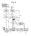
- a diesel engine 20 shown in Fig. 2 differs from the above-mentioned diesel engine 1 in the following.
- the diesel engine 1 has the injection-system fuel return passage 16 via which the return fuel after the supply to the injection system 12 is returned to the fuel tank 2.
- the diesel engine 20 has an injection-system fuel return passage 21 via which the return fuel after the supply to the injection system 12 is turned to the oil pan 3.
- the injection-system fuel return passage 21 can be shortened, and the degree of freedom of mounting the diesel engine 20 can be improved.
- the other structures of the diesel engine 20 are the same as corresponding those of the diesel engine 1. Thus, the parts commonly used in the diesel engines 1 and 20 are given the same reference numerals, and a description thereof will be omitted.
- a diesel engine 25 in accordance with a third embodiment, not forming part of the present invention.
- the diesel engine 25 differs from the diesel engine 1 of the first embodiment in the following.
- the diesel engine 1 has the injection-system fuel return passage 16 via which the return fuel after the supply to the injection system 12 is returned to the fuel tank 2.
- the diesel engine 25 has an injection-system fuel return passage 26 via which the return fuel after the supply to the injection system 12 is returned to the upstream side of the injection pump 15.
- the injection-system return fuel is returned to the upstream side of the filter 14 arranged on the upstream side of the injection pump 15, as indicated by arrows 27 and 28.
- the return fuel is supplied to the injection system 12 after filtered by the filter 14. Even if the return fuel is mixed with a foreign matter, the filter 14 removes the foreign matter, which is not supplied to the injection system 12. It is also possible to separate bubbles from the return fuel and avoid air ration in the injection system 12.
- the other structures of the diesel engine 25 are the same as corresponding those of the diesel engine 1. Thus, the parts commonly used in the diesel engines 1 and 25 are given the same reference numerals, and a description thereof will be omitted.
- a diesel engine 30 in accordance with a fourth embodiment, not forming part of the present invention.
- the diesel engine 30 differs from the diesel engine 1 of the first embodiment in the following.
- the diesel engine 1 has the injection-system fuel return passage 16 via which the return fuel after the supply to the injection system 12 is returned to the fuel tank 2.
- the diesel engine 30 has an injection-system fuel return passage 31 via which the return fuel that has been supplied to the injection system 12 is returned to the oil pan 3 and the upstream side of the injection pump 15.
- the injection-system fuel return passage 31 has a three-way valve 32, a first passage 34 and a second passage 36.
- the three-way valve 32 has three ports 32a, 32b and 32c and the degree of opening thereof can be adjusted.
- the first passage 34 is used to return the return fuel from the injection system 12 to the upstream side of the injection pump 15 as indicated by an arrow 33.
- the second passage 36 is used to return the return fuel from the injection system to the oil pan 3 as indicated by an arrow 35.
- the three-way valve 32 is capable of not only switching between the first passage 34 and the second passage 36 but also distributing the return fuel to the first passages 34 and 36 with a desired ratio.
- the three-way valve 32 may supply the return fuel to the injection pump 15, that is, the first passage 34 with an increased ratio when the diesel engine 30 is already warmed up.
- the three-way valve 32 may supply the return fuel to the oil pan, that is, the second passage 36 with an increased ratio when the diesel engine 30 is cold.
- the reasons for returning the return fuel from the injection system 12 to the oil pan 3 are as follows.
- the fuel in the oil pan 3 is supplied to the lubrication-system fuel supply passage 8 as well as the injection-system fuel supply passage 13, and functions as a lubricating oil. It is therefore desired that the fuel has an appropriate viscosity.
- the fuel When the engine is cold, the fuel is at a low temperature and a high viscosity. Thus, the temperature of fuel should be raised as soon as possible when the engine is cold.
- the three-way valve 32 is controlled based on the temperature of fuel to increase the degree of opening of the port 32b so that an increased amount of return fuel is fed to the oil pan 3 and the diesel engine 30 is warmed up quickly. This contributes to reduction of frictions in the diesel engine 30 and improvement in fuel economy.
- a temperature sensor may be used to determine whether the diesel engine 30 is already warmed up or cold. Such a temperature sensor may be attached to the oil pan 3 or the injection side of the injection pump 15. Instead of the oil temperature sensor, it is possible to use a water temperature sensor that senses the temperature of the engine cooling water.
- the first passage 34 via which the return fuel from the injection system 12 is returned to the injection pump 15 is connected to the upstream side of the filter 14 connected to the upstream side of the injection pump 15.
- the filter 14 removes the foreign matter, which is not supplied to the injection system 12. It is also possible to separate bubbles from the return fuel and avoid air ration in the injection system 12.
- the other structures of the diesel engine 30 are the same as corresponding those of the diesel engine 1. Thus, the parts commonly used in the diesel engines 1 and 30 are given the same reference numerals, and a description thereof will be omitted.
- a diesel engine 40 in accordance with a fifth embodiment, not forming part of the present invention.
- the diesel engine 40 differs from the diesel engine 1 of the first embodiment in the following.
- the diesel engine 1 has the injection-system fuel supply passage 13 in which the injection pump 15 pumps up fuel from the oil pan 3 only.
- the diesel engine 40 of the fifth embodiment has a mechanism such that fuel is pumped up from the fuel tank 2 as well as the oil pan 3.
- the injection-system fuel supply passage 13 has a three-way valve 41 provided on the upstream side of the injection pump 15 and connected to a fuel pipe 42 via which fuel is supplied from the fuel tank 2. That is, the diesel engine 40 is capable of directly pumping up fuel from the fuel tank 2.
- the three-way valve 41 has three ports 41 a, 4 1 b and 41 c, and the degree of opening thereof can be adjusted based on the temperature of fuel.
- the degree of opening of the three-way valve 41 is controlled to pump up fuel from the oil pan 3, as indicated by an arrow 43.
- the degree of opening of the three-way valve 41 is controlled to pump up fuel from the fuel tank 2, as indicated by an arrow 44.
- the pumping-up ratio for the fuel tank 2 and the oil pan 3 may be changed based on the temperature of fuel.
- the diesel engine 40 is equipped with the filter 14 interposed between the three-way valve 41 and the injection pump 15.
- the filter 14 removes the foreign matter, which is not supplied to the injection system 12. It is also possible to separate bubbles from the return fuel and avoid air ration in the injection system 12.
- the return fuel from the injection system 12 is returned to the fuel tank 2 via the injection-system return passage 16.
- the return fuel may be returned to the oil pan 3 via an injection-system return passage 21. This prevents hot fuel from being returned to the fuel tank 2 and makes it possible to pump up fuel at a lower temperature from the fuel tank 2 via the fuel pipe 42.
- the other structures of the diesel engine 40 are the same as corresponding those of the diesel engine 1. Thus, the parts commonly used in the diesel engines 1 and 40 are given the same reference numerals, and a description thereof will be omitted.
- Fig. 7 illustrates a diesel engine 45 in accordance with a sixth embodiment of the present invention.
- the diesel engine 45 differs from the diesel engine 20 of the second embodiment in the following.
- the diesel engine 20 has the injection-system return passage 21 via which the return fuel from the injection system 12 is returned directly to the oil pan 3.
- the diesel engine 45 has an injection-system fuel return passage 46 via which the return fuel from the injection system 12 is supplied to a valve train 7a among the engine parts 7, and is then returned to the oil pan 3 via the lubrication-system fuel return passage 11.
- the diesel engine 20 of the second embodiment is designed to supply, via the lubrication-system fuel supply passage 8, fuel to all parts (engine parts 7) that need a supply of lubricating oil such as the valve train 7a and the peripheral portion of the crankshaft.
- the diesel engine 45 is designed so that the engine parts 7 are separated into the valve train on the cylinder head side and the periphery of the crankshaft on the cylinder block side.
- the valve train 7a is supplied with the return fuel from the injection system 12, and the cylinder block is supplied with fuel from the lubrication-system fuel supply passage 8.
- the return fuel from the valve train 7a is merged with the lubrication-system fuel return passage, and is returned to the oil pan 3.
- the injection-system fuel return passage 46 can be shortened, and a reduced number of parts may be used. There is no need to extend the pipe of the lubrication-system fuel return passage 11 up to the valve train 7a, so that the return passage 11 can be simplified.
- the other structures of the diesel engine 45 are the same as corresponding those of the diesel engine 20 of the second embodiment. Thus, the parts commonly used in the diesel engines 20 and 45 are given the same reference numerals, and a description thereof will be omitted.
- Fig. 8 illustrates a diesel engine 50 in accordance with a seventh embodiment, not forming part of the present invention.
- the diesel engine 50 differs from the diesel engines 1 and 20 of the first and second embodiments in the following.
- the diesel engine I has the injection-system return passage 16 via which the return fuel from the injection system 12 is returned to the fuel tank 2.
- the diesel engine 20 has the injection-system fuel return passage 21 via which the return fuel from the injection system 12 is returned to the oil pan 3.
- the diesel engine 50 of the seventh embodiment has an injection-system fuel return passage 51 equipped with a three-way valve 52, a first passage 51a and a second passage 51b.
- the three-way valve 52 is capable of adjusting the degree of opening.
- the first passage 51a is used to return the return fuel from the injection system 12 to the oil pan 3.
- the second passage 51b is used to return the return fuel from the injection system 12 to the fuel tank 2.
- the diesel engine 50 can switch the destination of the return fuel between the fuel tank 2 and the oil pan 3 on the basis of the condition of the diesel engine 50.
- the three-way valve 52 returns the return fuel from the injection system 12 to the oil pan 3 via the first passage 51a when the engine is still cold during the warning up.
- the three-way valve 52 returns the return fuel from the injection system 12 to the fuel tank 2 via the second passage 51b.
- the return fuel having a high temperature raised during the warming up is returned to the oil pan 3, and raises the temperature of the fuel in the oil pan 3 quickly. This decreases the viscosity of the fuel in the oil pan 3 and contributes to reduction of frictions.
- the return fuel is returned to the fuel tank 2 after the engine is already warmed up and is hot, so that the return fuel can be cooled through the second passage 51b and fuel in the injection system 12 can be maintained in a restrained temperature.
- the first passage 51 a directly returns the return fuel from the injection system 12 to the oil pan 3.
- the return fuel may be supplied to primarily lubricated parts 7b among the engine parts 7. That is, when the engine is cold, the return fuel that has a raised temperature and a reduced viscosity is directly to the primarily lubricated parts 7b such as a crank journal, so that frictions can be reduced quickly.
- Fig. 10 shows an eight embodiment of the present invention.
- This embodiment is a variation of the embodiments having the fuel supply passage 4 equipped with the electrically powered supply pump 6.
- the present variation employs a fuel supply passage 60 equipped with a mechanical supply pump 61.
- the fuel supply passage 60 has a three-way valve 62 and a regulator 63 arranged in this order toward the downstream side.
- the three-way valve 62 is capable of adjusting the degree of opening and is equipped with a return pipe 64 via which excessive fuel among the fuel supplied to the three-way valve 62 from the mechanical supply pump 61 is returned to the upstream side of the pump 61.
- the mechanical supply pump 61 increases the fuel supply as the engine speed increases.
- the regulator 63 regulates the fuel supply to the oil pan 3.
- the degree of opening of the three-way valve 62 is adjusted so that the excessive fuel is returned to the upstream side of the mechanical supply pump 61.
- the excessive fuel is recycled in the given loop and the restrained amount of fuel can be supplied to the oil pan 3.
Landscapes
- Engineering & Computer Science (AREA)
- Mechanical Engineering (AREA)
- General Engineering & Computer Science (AREA)
- Chemical & Material Sciences (AREA)
- Combustion & Propulsion (AREA)
- Lubrication Of Internal Combustion Engines (AREA)
Claims (5)
- Moteur diesel (1) comprenant :un passage d'alimentation en carburant (4) via lequel le carburant est amené d'un réservoir de carburant (2) à un carter d'huile (3) en passant par une pompe d'alimentation (6) ;un passage d'alimentation en carburant de système de lubrification (8) via lequel le carburant est amené du carter d'huile (3) aux pièces du moteur (7) à lubrifier par une pompe d'huile de lubrification (10) ;un passage d'alimentation en carburant de système d'injection (13) via lequel le carburant est amené du carter d'huile (3) à un système d'injection (12) en passant par une pompe à injection (15) ; etun passage de retour de carburant de système de lubrification (11) via lequel le carburant de retour provenant des pièces du moteur (7) est ramené vers le carter d'huile, dans lequelun passage de retour de carburant de système d'injection (46) via lequel le carburant de retour provenant du système d'injection (12) est ramené vers le carter d'huile (3), caractérisé en ce quele passage de retour de carburant de système d'injection (46) ramène le fluide de retour vers des pièces données parmi les pièces du moteur (7) avant de ramener le carburant de retour au carter d'huile (3).
- Moteur diesel selon la revendication 1, dans lequel le carburant de retour est ramené à un système de dispositif de commande des soupapes (7a), et le carburant passant par le passage d'alimentation en carburant de système de lubrification (8) est amené à un bloc-cylindres.
- Moteur diesel selon les revendications 1 ou 2, dans lequel un orifice d'aspiration du passage d'alimentation en carburant de système d'injection (13) dans le carter d'huile (3) est positionné dans une position plus haute que celle à laquelle un orifice d'aspiration du passage d'alimentation en carburant de système de lubrification (8) est positionné.
- Moteur diesel selon l'une quelconque des revendications 1 à 3, dans lequel :la pompe d'alimentation (6) dans le passage d'alimentation en carburant (4) est une pompe d'alimentation mécanique (61) entraînée par un vilebrequin ;une soupape à trois voies (62) et un régulateur (63) sont agencés dans cet ordre vers le côté en aval par rapport à la pompe d'alimentation mécanique (61) ; etun tuyau de retour (64) est agencé via lequel le carburant en excès provenant de la pompe d'alimentation mécanique (61) est ramené vers un côté en amont de la pompe d'alimentation mécanique (61) en commandant le degré ajustable d'ouverture de la soupape à trois voies (62).
- Moteur diesel selon l'une quelconque des revendications 1 à 4, dans lequel la pompe d'alimentation (6) est une pompe électrique, et une quantité de décharge de la pompe électrique est commandée en fonction d'une condition du moteur.
Applications Claiming Priority (2)
| Application Number | Priority Date | Filing Date | Title |
|---|---|---|---|
| JP2004380153A JP4248492B2 (ja) | 2004-12-28 | 2004-12-28 | 軽油等燃料潤滑ディーゼルエンジン |
| PCT/JP2005/024204 WO2006070905A1 (fr) | 2004-12-28 | 2005-12-26 | Moteur diesel lubrifie avec un carburant tel que de l'huile legere |
Publications (2)
| Publication Number | Publication Date |
|---|---|
| EP1831508A1 EP1831508A1 (fr) | 2007-09-12 |
| EP1831508B1 true EP1831508B1 (fr) | 2013-09-11 |
Family
ID=36121396
Family Applications (1)
| Application Number | Title | Priority Date | Filing Date |
|---|---|---|---|
| EP05851005.8A Expired - Lifetime EP1831508B1 (fr) | 2004-12-28 | 2005-12-26 | Moteur diesel lubrifie avec un carburant tel que de l'huile legere |
Country Status (5)
| Country | Link |
|---|---|
| US (2) | US7461637B2 (fr) |
| EP (1) | EP1831508B1 (fr) |
| JP (1) | JP4248492B2 (fr) |
| CN (1) | CN1957160B (fr) |
| WO (1) | WO2006070905A1 (fr) |
Families Citing this family (11)
| Publication number | Priority date | Publication date | Assignee | Title |
|---|---|---|---|---|
| JP4631860B2 (ja) * | 2007-02-19 | 2011-02-16 | トヨタ自動車株式会社 | 多種燃料内燃機関 |
| ITBO20080259A1 (it) * | 2008-04-23 | 2009-10-24 | Acma Spa | Convogliatore rotante per macchine operative atte alla manipolazione di contenitori, in particolare per macchine tappatrici, e macchina tappatrice provvista di tale convogliatore rotante. |
| US8104449B2 (en) * | 2008-05-19 | 2012-01-31 | Ford Global Technologies, Llc | Water reduction mechanism for an internal combustion engine |
| US8556038B2 (en) * | 2009-03-11 | 2013-10-15 | Toyota Jidosha Kabushiki Kaisha | Lubricating device |
| DE102011075793A1 (de) * | 2011-05-13 | 2012-11-15 | Robert Bosch Gmbh | Brennkraftmaschine und Kraftstofffördereinrichtung |
| US9334769B2 (en) | 2013-01-25 | 2016-05-10 | Cummins Power Generation Ip, Inc. | Apparatuses, systems, and methods for crankcase oil sump overfill protection |
| US20140224215A1 (en) * | 2013-02-08 | 2014-08-14 | Martin A. Lehman | Fuel filtration system |
| US9371825B2 (en) * | 2013-02-28 | 2016-06-21 | Gary W. Zaremba | Fuel tank arrangements for self-priming floating pumps |
| CN103196023A (zh) * | 2013-04-02 | 2013-07-10 | 福建永强力加动力设备有限公司 | 一种适用流水作业的循环供油系统 |
| CN104879490A (zh) * | 2015-04-21 | 2015-09-02 | 常州东风无级变速器有限公司 | 高功能安全性的无级变速器 |
| CN117738981A (zh) * | 2023-12-29 | 2024-03-22 | 广州汽车集团股份有限公司 | 冷却系统、冷却方法和车辆 |
Family Cites Families (13)
| Publication number | Priority date | Publication date | Assignee | Title |
|---|---|---|---|---|
| FR834339A (fr) * | 1937-07-21 | 1938-11-17 | Andre Citroe N | Procédé et dispositif pour l'utilisation des huiles combustibles dans les moteurs à combustion |
| GB720222A (en) | 1952-07-07 | 1954-12-15 | Cav Ltd | A lubrication and fuel oil system for internal combustion engines |
| JPS5581214A (en) | 1978-12-13 | 1980-06-19 | Nissan Motor Co Ltd | Light-oil lubrication type diesel engine |
| JPS5627015A (en) | 1979-08-10 | 1981-03-16 | Nissan Motor Co Ltd | Diesel engine of light-oil lubrication type |
| JPS578309A (en) | 1980-06-20 | 1982-01-16 | Nissan Motor Co Ltd | Lubrication method for internal combustion engine |
| JPS60194112A (ja) | 1984-03-14 | 1985-10-02 | Asahi Chem Ind Co Ltd | アクリル系合成繊維 |
| US4787348A (en) * | 1988-01-25 | 1988-11-29 | Parker Automotive Corporation | Carbon-cleaning apparatus for diesel engines |
| US6209508B1 (en) | 1997-03-03 | 2001-04-03 | Science Applications International Corp. | Four-cycle fuel-lubricated internal combustion engine |
| DE19747854A1 (de) * | 1997-10-30 | 1999-05-12 | Fuchs Petrolub Ag | Verfahren und Vorrichtung zur Schmierung und gleichzeitigen Kraftstoffversorgung eines pflanzenöl-tauglichen Verbrennungsmotors |
| DE19817976C2 (de) | 1998-04-22 | 2002-05-16 | Anlagen Und Antriebstechnik No | Verfahren zum Betreiben eines Motors mit einem viskosen, brennbaren, flüssigen Kraftstoff, vorzugsweise einem Naturöl |
| JP2000329008A (ja) | 1999-05-14 | 2000-11-28 | Hisao Matsumoto | 植物油によるデイーゼル機関駆動におけるワンスルーシステムの構成方法 |
| US6446612B1 (en) * | 2000-10-25 | 2002-09-10 | James Dwayne Hankins | Fuel injection system, components therefor and methods of making the same |
| DE10061987B4 (de) | 2000-12-13 | 2005-06-16 | Robert Bosch Gmbh | Verfahren und Vorrichtung zum Kühlen einer Kraftstoffeinspritzanlage |
-
2004
- 2004-12-28 JP JP2004380153A patent/JP4248492B2/ja not_active Expired - Fee Related
-
2005
- 2005-12-26 CN CN2005800162861A patent/CN1957160B/zh not_active Expired - Fee Related
- 2005-12-26 US US10/592,005 patent/US7461637B2/en not_active Expired - Fee Related
- 2005-12-26 EP EP05851005.8A patent/EP1831508B1/fr not_active Expired - Lifetime
- 2005-12-26 WO PCT/JP2005/024204 patent/WO2006070905A1/fr not_active Ceased
-
2008
- 2008-11-10 US US12/267,713 patent/US7699037B2/en not_active Expired - Fee Related
Also Published As
| Publication number | Publication date |
|---|---|
| US7699037B2 (en) | 2010-04-20 |
| EP1831508A1 (fr) | 2007-09-12 |
| JP4248492B2 (ja) | 2009-04-02 |
| WO2006070905A1 (fr) | 2006-07-06 |
| US20090071435A1 (en) | 2009-03-19 |
| US7461637B2 (en) | 2008-12-09 |
| JP2006183618A (ja) | 2006-07-13 |
| US20080035099A1 (en) | 2008-02-14 |
| CN1957160B (zh) | 2010-05-05 |
| WO2006070905B1 (fr) | 2006-09-14 |
| CN1957160A (zh) | 2007-05-02 |
Similar Documents
| Publication | Publication Date | Title |
|---|---|---|
| US7699037B2 (en) | Diesel engine lubricated with fuel such as light oil | |
| US6823845B2 (en) | Fuel injection system with improved regulation of pumping quantities | |
| US6647938B2 (en) | Supply pressure pump with separate drive on an internal combustion engine | |
| GB2480474A (en) | Engine piston cooling jet oil supply system comprising a pressure operated valve | |
| JP2007285235A (ja) | ディーゼルエンジンの燃料供給装置 | |
| US7823545B2 (en) | Piston squirter system and method | |
| JP2003206824A (ja) | インジェクションポンプ、及び該インジェクションポンプを備えたディーゼルエンジンのdme燃料供給装置 | |
| US6955142B2 (en) | Piston and cylinder oil squirter rail and system | |
| JP2013142297A (ja) | 内燃機関の潤滑油供給装置 | |
| JP2008128228A (ja) | 高圧ポンプ用の燃料調整及び濾過装置 | |
| JP2006249940A (ja) | エンジン | |
| GB2595874A (en) | A method for operating a lubricating and piston cooling system for an engine of a vehicle and a lubricating and piston cooling system | |
| JP2008280969A (ja) | オイル供給装置 | |
| JP2007224760A (ja) | シリンダ潤滑装置 | |
| JP4414877B2 (ja) | 軽油等燃料潤滑ディーゼルエンジン | |
| JP4327712B2 (ja) | 軽油等燃料潤滑ディーゼルエンジン | |
| GB2591272A (en) | Internal combustion engine for a vehicle | |
| JPH11324831A (ja) | エンジンの燃料冷却装置 | |
| JP4185909B2 (ja) | 軽油等燃料潤滑ディーゼルエンジン | |
| JP2007113499A (ja) | オイルタンク油量制御装置及び軽油等燃料潤滑ディーゼルエンジン | |
| US6854431B2 (en) | Internal combustion engine comprising a hydraulic system | |
| JP2008223734A (ja) | 潤滑装置 | |
| JP2006257919A (ja) | 軽油等燃料潤滑ディーゼルエンジン | |
| JP2009138574A (ja) | エンジン | |
| JP2006214372A (ja) | 軽油等燃料潤滑ディーゼルエンジン |
Legal Events
| Date | Code | Title | Description |
|---|---|---|---|
| PUAI | Public reference made under article 153(3) epc to a published international application that has entered the european phase |
Free format text: ORIGINAL CODE: 0009012 |
|
| 17P | Request for examination filed |
Effective date: 20060824 |
|
| AK | Designated contracting states |
Kind code of ref document: A1 Designated state(s): DE FR GB |
|
| 17Q | First examination report despatched |
Effective date: 20071114 |
|
| DAX | Request for extension of the european patent (deleted) | ||
| RBV | Designated contracting states (corrected) |
Designated state(s): DE FR GB |
|
| RIC1 | Information provided on ipc code assigned before grant |
Ipc: F02M 63/02 20060101ALI20111116BHEP Ipc: F02M 63/00 20060101AFI20111116BHEP |
|
| RIC1 | Information provided on ipc code assigned before grant |
Ipc: F02M 63/00 20060101ALI20111123BHEP Ipc: F02M 63/02 20060101ALI20111123BHEP Ipc: F01M 9/04 20060101AFI20111123BHEP |
|
| RAP1 | Party data changed (applicant data changed or rights of an application transferred) |
Owner name: TOYOTA JIDOSHA KABUSHIKI KAISHA |
|
| GRAP | Despatch of communication of intention to grant a patent |
Free format text: ORIGINAL CODE: EPIDOSNIGR1 |
|
| GRAS | Grant fee paid |
Free format text: ORIGINAL CODE: EPIDOSNIGR3 |
|
| GRAA | (expected) grant |
Free format text: ORIGINAL CODE: 0009210 |
|
| RIN1 | Information on inventor provided before grant (corrected) |
Inventor name: MURAKAMI, MOTOICHI, Inventor name: ONO, TOMOYUKI, Inventor name: YAMASHITA, AKIRA, Inventor name: MORITANI, HIROSHI, Inventor name: OHMORI, TOSHIHIDE, |
|
| AK | Designated contracting states |
Kind code of ref document: B1 Designated state(s): DE FR GB |
|
| REG | Reference to a national code |
Ref country code: GB Ref legal event code: FG4D |
|
| RIN2 | Information on inventor provided after grant (corrected) |
Inventor name: MURAKAMI, MOTOICHI Inventor name: ONO, TOMOYUKI Inventor name: YAMASHITA, AKIRA Inventor name: OHMORI, TOSHIHIDE Inventor name: MORITANI, HIROSHI |
|
| REG | Reference to a national code |
Ref country code: DE Ref legal event code: R096 Ref document number: 602005041234 Country of ref document: DE Effective date: 20131114 |
|
| REG | Reference to a national code |
Ref country code: GB Ref legal event code: 746 Effective date: 20140304 |
|
| REG | Reference to a national code |
Ref country code: DE Ref legal event code: R084 Ref document number: 602005041234 Country of ref document: DE Effective date: 20140304 |
|
| REG | Reference to a national code |
Ref country code: DE Ref legal event code: R097 Ref document number: 602005041234 Country of ref document: DE |
|
| PLBE | No opposition filed within time limit |
Free format text: ORIGINAL CODE: 0009261 |
|
| STAA | Information on the status of an ep patent application or granted ep patent |
Free format text: STATUS: NO OPPOSITION FILED WITHIN TIME LIMIT |
|
| 26N | No opposition filed |
Effective date: 20140612 |
|
| REG | Reference to a national code |
Ref country code: DE Ref legal event code: R097 Ref document number: 602005041234 Country of ref document: DE Effective date: 20140612 |
|
| PGFP | Annual fee paid to national office [announced via postgrant information from national office to epo] |
Ref country code: GB Payment date: 20141224 Year of fee payment: 10 |
|
| PGFP | Annual fee paid to national office [announced via postgrant information from national office to epo] |
Ref country code: FR Payment date: 20141208 Year of fee payment: 10 |
|
| PGFP | Annual fee paid to national office [announced via postgrant information from national office to epo] |
Ref country code: DE Payment date: 20141223 Year of fee payment: 10 |
|
| REG | Reference to a national code |
Ref country code: DE Ref legal event code: R119 Ref document number: 602005041234 Country of ref document: DE |
|
| GBPC | Gb: european patent ceased through non-payment of renewal fee |
Effective date: 20151226 |
|
| REG | Reference to a national code |
Ref country code: FR Ref legal event code: ST Effective date: 20160831 |
|
| PG25 | Lapsed in a contracting state [announced via postgrant information from national office to epo] |
Ref country code: DE Free format text: LAPSE BECAUSE OF NON-PAYMENT OF DUE FEES Effective date: 20160701 Ref country code: GB Free format text: LAPSE BECAUSE OF NON-PAYMENT OF DUE FEES Effective date: 20151226 |
|
| PG25 | Lapsed in a contracting state [announced via postgrant information from national office to epo] |
Ref country code: FR Free format text: LAPSE BECAUSE OF NON-PAYMENT OF DUE FEES Effective date: 20151231 |