EP1831850B1 - Systeme de detection d'emplacement pour personnes, animaux et objets - Google Patents
Systeme de detection d'emplacement pour personnes, animaux et objets Download PDFInfo
- Publication number
- EP1831850B1 EP1831850B1 EP05823582A EP05823582A EP1831850B1 EP 1831850 B1 EP1831850 B1 EP 1831850B1 EP 05823582 A EP05823582 A EP 05823582A EP 05823582 A EP05823582 A EP 05823582A EP 1831850 B1 EP1831850 B1 EP 1831850B1
- Authority
- EP
- European Patent Office
- Prior art keywords
- transceiver
- position finding
- finding system
- transmitter
- transceivers
- Prior art date
- Legal status (The legal status is an assumption and is not a legal conclusion. Google has not performed a legal analysis and makes no representation as to the accuracy of the status listed.)
- Expired - Lifetime
Links
Images


Classifications
-
- G—PHYSICS
- G01—MEASURING; TESTING
- G01S—RADIO DIRECTION-FINDING; RADIO NAVIGATION; DETERMINING DISTANCE OR VELOCITY BY USE OF RADIO WAVES; LOCATING OR PRESENCE-DETECTING BY USE OF THE REFLECTION OR RERADIATION OF RADIO WAVES; ANALOGOUS ARRANGEMENTS USING OTHER WAVES
- G01S5/00—Position-fixing by co-ordinating two or more direction or position line determinations; Position-fixing by co-ordinating two or more distance determinations
- G01S5/02—Position-fixing by co-ordinating two or more direction or position line determinations; Position-fixing by co-ordinating two or more distance determinations using radio waves
- G01S5/0284—Relative positioning
- G01S5/0289—Relative positioning of multiple transceivers, e.g. in ad hoc networks
-
- G—PHYSICS
- G08—SIGNALLING
- G08B—SIGNALLING SYSTEMS, e.g. PERSONAL CALLING SYSTEMS; ORDER TELEGRAPHS; ALARM SYSTEMS
- G08B21/00—Alarms responsive to a single specified undesired or abnormal condition and not otherwise provided for
- G08B21/02—Alarms for ensuring the safety of persons
- G08B21/0202—Child monitoring systems using a transmitter-receiver system carried by the parent and the child
- G08B21/0272—System arrangements wherein the object is to detect exact location of child or item using triangulation other than GPS
-
- G—PHYSICS
- G08—SIGNALLING
- G08B—SIGNALLING SYSTEMS, e.g. PERSONAL CALLING SYSTEMS; ORDER TELEGRAPHS; ALARM SYSTEMS
- G08B21/00—Alarms responsive to a single specified undesired or abnormal condition and not otherwise provided for
- G08B21/02—Alarms for ensuring the safety of persons
- G08B21/0202—Child monitoring systems using a transmitter-receiver system carried by the parent and the child
- G08B21/0227—System arrangements with a plurality of child units
-
- G—PHYSICS
- G08—SIGNALLING
- G08B—SIGNALLING SYSTEMS, e.g. PERSONAL CALLING SYSTEMS; ORDER TELEGRAPHS; ALARM SYSTEMS
- G08B21/00—Alarms responsive to a single specified undesired or abnormal condition and not otherwise provided for
- G08B21/02—Alarms for ensuring the safety of persons
- G08B21/0202—Child monitoring systems using a transmitter-receiver system carried by the parent and the child
- G08B21/0238—Child monitoring systems using a transmitter-receiver system carried by the parent and the child adding new units to the system
Definitions
- the present invention relates to an innovatory electronic system for the position finding of people, animals, and things.
- the position finding process of the first family allows the approximate distance of a "GSM” terminal from the base radio station to which it is connected to be detected.
- BTS surrounding cells
- trigonometric triangulation it is possible to take the approximate bearing of the location of a mobile phone over the area.
- the bearing of the location of a "GSM” terminal could be taken by using the already available information of the "GSM” network, without controlling in any way the mobile phones.
- the position finding is called "cell-based" position finding, i.e.
- the omnidirectional cell is formed by antennas radiating to all directions and allows the location of a terminal to be detected with a maximum precision equal to the radius of the cell, i.e. it can be only stated that the terminal is within the covering area of the cell.
- the omnidirectional cell associated with time advance allows the position finding precision to be increased as the network induces the mobile phone to perform a connection and calculates the distance between terminal and antenna on the basis of the transmission delay time, thus reducing the position finding area from a circle to a circular crown.
- the terminal is then spotted inside a crown but the angular position of the same is still unknown.
- the station radiates towards several sectors, thus allowing the terminal to be spotted with the maximum precision of the sector covered by the cell even if, however, the distance from the antenna is unknown.
- the sector cell associated with time advance allows the area position finding precision to be increased, such area being reduced from a circular sector to a circular crown sector but also in this case its angular position remains unknown.
- the “GPS” Global Positioning System
- GPS Global Positioning System
- the “GPS” Global Positioning System
- It is based upon the principle of reception of radio signals from artificial satellites which are processed on earth by measurement apparatus to find the location of a person, animal, or object.
- Such system is based upon trigonometric calculations and iterations having as fixed reference point the propagation speed of the electromagnetic waves, each "GPS" transceiver being able to receive simultaneously the radio signals from a plurality of satellites and to calculate the distance from the latter on the basis of the received different information.
- any type of "GPS" apparatus is a receiver only, therefore it is not able to transmit any information.
- the "GPS” system has been then integrated with the "GSM” system because a "GSM” mobile radio system coupled to a satellite receiver allows the coordinates of the detected position to be sent to the user.
- the "GPS + GSM” system is most used to send data generated by a "GPS” by using the cellular telephone system in real time, although such system as well as the satellite antitheft device is still very expensive today.
- Wireless systems generally are used for the communication, monitoring and service of control systems in which the signals propagate like waves through the space and not through wires or transmission cables.
- the transmission is mainly carried out via radiofrequency (RF) or via infrared (IR).
- the wireless position finding systems in the simplest form of identification systems, consist of cards provided with microchips for logic and radio communication functions via antenna, the so-called transponder, and a radiofrequency reading device that receives and decodes the information contained therein. The information red is then transmitted on a net and processed.
- RFID wireless identification systems
- Another little advantageous reason of said systems is the presence of different standards. This has prevented such systems from being widely spread as effective position finding systems.
- Wireless technology based upon the transmission of radio waves emitted by a transmitter (that can be put inside a bracelet, watch, etc.) allows the waves to be picked up by a plurality of receivers. Also in this case the detection of the distance from the transmitter to the receiver can mainly be carried out by two different modes, i.e. the measurement of both the radio signal power and the time taken by the same radio signal to reach the receiver. The most precise definition of the position occupied by the transmitter is instead obtained by a triangulation.
- Position finding systems of this type are, for example, those using "Wi-Fi” technology or those used by Beghelli and Quik Trak; even if there are many companies that operate in the production of position finding systems, only the above-mentioned companies are disclosed thereafter showing up their limitations and drawbacks as they are more representative of the wireless technology applied to the lookout for people, animals, and things.
- the "Wi-Fi” (“Wireless Fidelity”) system is a technology that allows data to be exchanged at high rate (11 to 54 Mbit per second) without using any net cable, but keeping a complete freedom of movement.
- Wi-Fi transmits via radio usually at the frequency of 2.45 GHz and is based on IEEE 802.11 standard (Institute of Electrical and Electronics Engineers) allowing fast wireless connections to Internet. It is enough to install the wireless card into the computer, to look for an antenna radiating the signal (hotspot) and to start wide band navigation.
- the wireless card is able to transfer data between personal computers by using a signal based on highfrequency radio waves.
- the communication is ensured by the use of suitable devices interfaced with PCs able to transmit and receive radio signals. Just this r capability of transmitting a signal is at the base of a position finding system with "Wi-Fi" technology.
- the minimum configuration requires only two computers, both provided with a "Wi-Fi" card and located within a range of one hundred metres to create a wireless net.
- any computer provided with a "Wi-Fi” card in the range of one hundred metres holds a dialogue not only with all other PCs but can also have free access to Internet.
- the position finding system so-called "Safe Child” of Beghelli consists of a receiving base unit under the control of an adult which emits an acoustic signal as the child provided with a transmitting bracelet moves away beyond a predetermined distance which can be regulated according to three different values. Actually, such position finding system is not based on a net but is limited to an exchange of information between only two units. To calculate the distance between transmitter and receiver the device "Safe Child” calculates the power of the received signal which is a function of the distance but only in case of lack of obstacles between the same transmitter and receiver.
- GSM Global System for Mobile Communications
- GPS + GSM and “GSM” position finding systems have the further drawback of high power consumption that prevent them from being used in comfortable and durable manner with autonomy of operation as far as a particular type of users such as children, animals, and objects without power supply is concerned.
- GSM Global System for Mobile Communications
- the "GSM" position finding service is at the moment a service that has some difficulty in being spread by the same telephone service providers and police.
- EP-A-1282095 From EP-A-1282095 , US-B2-6674368 , US-B1-6693585 and EP-A-0811959 , are known systems for autoforming network or systems for finding the position of people, animals or objects.
- a first drawback of such known systems consists in that each of the units or devices therein disclosed comprise both a transmitter and a receiver.
- a second drawback of such known autoforming network systems is that said autoforming is not automatic, but require that each new transceiver has been set into a configuration mode.
- a third drawback of said known systems is that each unit must contain data concerning its position.
- a fourth drawback of said known systems is that said plurality of transceiver or tags or units need mutual identification.
- the main object of the present invention is to fully overcome the limitations and the drawbacks of the previously disclosed systems by providing an innovative system for the position finding of people, particularly children, animal, and things by a new network of wireless transceivers and transmitters with low power consumption.
- a further object of the present invention is at the same time to provide a reliable product of simple, practical use and above all low cost at the reach of everybody, even if it is based upon the wireless technology and creates suitable combinations of known technologies (such as for example GPS, GSM/UMTS, UMTS, RFID).
- position finding system 1 shown thereby relates to a simple, cheap, effective application of position finding system 1 such as to be used in those environments where the application of "GPS", “GPS + GSM” and “Wi-Fi” systems is totally or partly unsuited or insufficient because of complexity, cost and autonomy of operation or where the existing technology is not able to provide a qualitatively high service, for example, to make information available also via network as it is the case for the system "Safe Child” of Beghelli.
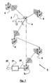
- the main feature of the present position finding system 1 as shown in figures 1 and 5 is actually the possibility of exchanging information among the several transceivers 3 with open protocols to support a number of applications (home automation, remote reading, RFID, traffic data, etc.) by using suitable frequencies (bands of 400 MHz, 800 MHz, 2.4 GHz).
- Transceivers 3 as well as transmitter 4 are provided with hardware and software with low power consumption.
- transceivers 3 communicate to one another both directly and indirectly via network, for example, by a connection to a predetermined address, thus establishing an "autoforming network", i.e.
- a network which is created and extended automatically at each new installation of a transceiver 3 and is able to increase the position finding range of each single transceiver 3 so that a generic transceiver 3.1 interconnected via network can start the position finding of the location of the child, thing or animal 2 to be found out, even if the latter is located at a distance which is far greater than the nominal range of transceiver 3.1 as it is possible to set up a communication among a plurality of position finding systems.
- the inventive concept is concerned with the expansion of the interception radius of the generic transceiver 3.1 which can be obtained by connecting it via network to such a plurality of transceivers 3 and by processing the information sent by transmitter 4 and collected by such a plurality of transceivers 3 operating like a bridge for the generic transceiver 3.1 connected via network.
- a further inventive concept is also concerned with the mode of setting up the network which is then "autoforming", i.e. it is created and extended automatically upon each new installation of a transceiver 3 which can be purchased by both private users and companies which invest in the position finding services or in their installation.
- the network is created without the need of an expensive installation of suitable network facilities, and the transceivers operating as bridges are the same transceiver 3 that also provide individually the interception service in their own covering area and allow a network to be autoformed without the need for the design and/or installation thereof in advance. It is evident that the interception service will be the more reliable and expanded the more transceivers 3 will be installed for individual use.
- the present system provides signal routing nets that are designed unlike the installation in a suitable way, i.e. the protocol used will have an automatic signal routing able to provide predetermined paths for a communication from a transceiver to another one specific for that suitable connection which is necessary because a new user (transmitter, but also transceiver) has joined the system.
- the inventive concept of the position finding system disclosed is inherent in the information exchange among the several transceivers or base unit 3 which are able to operate as receivers and also as transmitter of information to other transceivers 3.
- Some transceivers 3, additionally, are also provided with a (fixed or mobile) telephone for the connection to Internet to supply the public telephone service with the information collected.
- a (fixed or mobile) telephone for the connection to Internet to supply the public telephone service with the information collected.
- the size of each such cell depends on the topographic, geographic configuration of the territory as well as the average traffic of data, the number of repetitions of information provided by the protocol, the average range of the signal, and the quality of the service ensured.
- the several transceivers 3 are going to set up a network which is far wider with respect to the range of the single transceiver 3 and arranged to be expanded automatically at each new entry of a transceiver 3 by the users into the network.
- At least a pair of transceivers 3 is provided initially, both of them being able to exchange information with other base stations via air, and at least one of them being also provided with a socket 5 for PN/modem/LAN (PN stands for Public Network, or PSTN stands for Public Switched Telephonic Network or still PLMTN stands for Public Land Mobile Telephonic Network, i.e. telephonic or not, public networks such as Internet with circuit or packet switching; modem stands for an analogue or SDSL modem or other modems connected to a PN) for the connection to public network 22 as it is inferred from the preferred, not limiting embodiment with accessories shown in figures 1 and 2 .
- PN Public Network
- PSTN Public Switched Telephonic Network
- PLMTN Public Land Mobile Telephonic Network
- modem stands for an analogue or SDSL modem or other modems connected to a PN
- Transceivers 3 of the latter embodiment have to be necessarily installed at fixed points, for example balconies or terraces of single or condominial houses as well as provided with telephone sockets for the connection to Internet to allow all acquired information to be exchanged via network.
- the network service providers usually propose credit facilities to anyone will decide to choose such type of transceiver 3 and to carry out the installation. Instead, the one who won't connect his/her own transceiver 3 to public network 22 can always purchase the standard embodiment without output 5 to public network/modem/LAN.
- a "GPS + GSM/UMTS” module or the like can be put into GPS transceiver 3 so that socket 5 for PN/modem/LAN as well as the fixed location of transceiver 3 is not necessary.
- GPS + GSM/UMTS module in the transceiver allows the position finding in case of not fixed relay station which is, for example, installed on board of a car or other vehicles, or generally where a transceiver 3 or a plurality of transmitters 4 can be installed.
- the socket for PN/modem/LAN is arranged in models connected both directly to telephone system 22 and an outside modem 21 by means of a suitable connection cable 20, and also to a LAN.
- a socket for data transmission to modem for example a standard serial gate RS232
- the connecting cable 20 will be of the suitable type.
- transceiver 3 The one who would like to use only the on-line position finding service for spotting the position of a child, animal or object 2 through the access to the net but he/she wasn't interested in the purchase of transceiver 3, he/she can receive an acoustic alarm through his/her cellular phone if the object or the child or the animal 2 to be found out should move away beyond a certain distance from a predetermined area already covered by other transceivers 3, thus making use in any way of the service even if at a different cost.
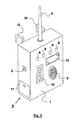
- Transceiver 3 is provided with a case 7 which can be manufactured with a suitable protection degree (for example IP 54).
- Transceiver 3 of a preferred embodiment shown in fig. 2 is mainly provided with an antenna 6 preferably positioned outside case 7 of transceiver 3, a plurality of light emitting diodes or LED 8 with switch 10 for the calibration in the field, a warning horn 9, a battery room 11, and at least a fixed support means 12 of transceiver 3 for wall or balcony.
- said transceiver 3 is also provided with a socket 5 for PN/modem/LAN for the connection of transceiver 3 via network, a socket for outside power supply, a keyboard 10 for regulating the acoustic signal intensity, the calibration in the field, and other optional functions, and a display 13 which is a further visual means or replaces said plurality of led 8.
- the power supply for the transceiver can be taken directly from the socket 5 for PN/modem/LAN.
- a third preferred embodiment of the present system is characterized by a kit consisting of a transceiver 3.1 provided with integrated "GPS + GSM/UMTS" module for the solution of the specific problem of the position finding of groups of things/people/animals 2 (or more generally "objects” 2) that can move over geographically wide territories even if they always stay together in a group.
- the transceiver is arranged for remote sending, automatically or on request, the information relative to the position as well as, which is more important, relative to how many objects 2 are present in the interception range through public network to a web site or through short message service (SMS) of cellular phones, with the possibility of setting up an alarm function in case of a missing signal from only one monitored object 2.
- SMS short message service
- the latter application of the present position finding system can be useful to allow elderly people and children upon going on a trip or walking within an area to be spotted, as well as works of art transported from a museum to another for temporary or travelling art exhibitions to be found out, etc.
- Transceivers 3.1 have a known position as they are connected to the public network through socket 5 for PN/MODEM/LAN, but generally and when not connected to the public network, the information relative to their position is transmitted via radio or via cable upon installation and stored in memory. Therefore, said transceivers 3.1 are able to communicate their positions in association with an information relative to reliability of their positions. In fact, these positions could be derived from the GPS coordinates in case of transceiver 3.1 with internal GPS+GSM/UMTS option, or fixed by the operator upon fixed installation. In the latter case, transceiver 3 or 3.1 is able to operate by a firmware routine in case the information is little reliable because it:
- transceivers 3.1 provided with internal GPS+GSM/UMTS module As far as transceivers 3.1 provided with internal GPS+GSM/UMTS module is concerned, a fourth preferred embodiment equipped with portable container for installation, for example, on board of vehicles can also be proposed.
- the power supply is derived from the same vehicle: the battery of the vehicle is the back-up, and a connection cable or a bluetooth module or the like is connected directly to socket or connector 5 for PN/MODEM/LAN.
- the latter (cable and bluetooth module) allow the connection to:
- transceiver 3 will use a communication format which is compatible with GPS systems or the like (for example "NMEA” or the like) as it is the case in the communication of position data among transceivers or repeaters 3 and 3.1.
- NMEA GPS systems or the like
- the "autoforming" network” takes into consideration transceivers 3 and 3.1 in the same way as transmitters 4 and then takes the bearing of the parameters detected thereby.
- the protocol among repeaters 3 and 3.1 and transmitters 4 is able to communicate at a speed of 100 km/h such that also a travelling vehicle can be used as mobile transceiver to widen the range of interception of the network of transceivers 3.1.
- the protocol is open, i.e. the fields of its frame can also be used for general applications, the repeaters or transceivers 3.1 are allowed to be used for data communication among vehicles.
- the communication protocol of transceivers 3 and 3.1 is such as to allow, in addition to remote reading of apparatus, home automation, and traffic data, also the reading of RFID transponder of new generation (worldwide standard "EPC" of second generation) in standards UHF and/or 2.4 GHz, or if enabled via firmware (for example in factory, upon installation or afterwards via ratio) it can transmit beacons capable of operating the transponders existing in their range to allow them to be spotted and identified.
- EPC electronic circuitry
- Transceiver 3 can be in the form of a OEM card that can be integrated within a common satellite navigator available on the market.
- Transmitter 4 according to a preferred embodiment shown schematically in fig. 3 consists of a shock-resistant case 14 with protection degree IP 54 having small size and provided with a serial number of identification 15 of the transmitter included therein as well as an antenna 16 preferably outside case 14 and of flexible type to keep size and weakness to a minimum.
- Transmitters 4 or devices to be positioned on objects 2 to be found out could also be used as receivers having hardware and firmware similar to those of transceivers 3 and 3.1, in particular in other preferred applications as follows:
- transmitters 4 can optionally be provided also with internal sensors (for sensing atmospheric pressure, temperature, humidity, etc.) to allow data detected by the same sensors to be transmitted together with data of its identification and position.
- Case 14 is also provided with hook means 17 for securing a belt, collar, necklace or any other means 18 to make transmitter 3 integral with child, animal or moving object 2 to be found out in time.
- Position finding system 1 is also characterized by the high autonomy of operation of the batteries as they allow a minimum range of 3-4 years for the transmitter and 4-5 years for the transceiver so that the replacement of such batteries is occasional.
- AAA thionyl lithium chloride cells of 3.6 V for transmitter 4 and "C" cells for transceiver 3 are used.
- transmitter 4 which has a peak of 25 thousandth Watt as a maximum and is lower than one thousandth Watt on average, has the advantage that transmitter 4 may be secured continuously to subjects particularly sensitive to electromagnetic pollution such as children, thus minimising the risks.
- the disclosed position finding system 1 can easily be adapted to a number of applications owing to said open protocol compatible with the standard for the supply of further services (for example remote reading of meters, home automation, traffic data, etc.).
- position finding system 1 can in any case be coupled with "GPS + GSM/UMTS", “GSM/UMTS”, “BLUETOOTH” and infrared modules or the like.
- the invention is also characterized by a high quality, reliability, easiness of operation, high autonomy of operation, small size, low cost, ecological compatibility, and crossed exchange of information among the single units and the network.
- the design of the preferred embodiments of the invention has required to cope with complex technical, scientific problems solved by a suitable selection of the individual SMD components on cards with small size and a suitable design of FW and particularly a communication protocol such as to fulfil the expected performance such as the signal transmission mode, range, data updating frequency and so on.
- Position finding system 1 of the present invention makes use of low-power technology for the chips of transmitter 4 and transceivers 3 and is characterized by low cost because of the simplicity of the adopted technology, and the open protocol allows the range of the possible applications to be widened as well as GPS + GSM/UMTS", “GSM/UMTS”, “BLUETOOTH” and infrared modules or the like to be coupled.
- transmitter 4 and transceiver 3.1 use a GPS module in low-power mode coupled with an internal wireless SRD module, they can make use of their internal memory to store their positions and, in case of transceivers 3.1, the memory of other transmitters 4 in all time intervals in which they could not be previously spotted by transceivers 3, 3.1 so that said positions can be thereafter transmitted via radio.
- Said coupling has the advantage of receiving information also from not fixed transceivers 3.1 and transmitters 4, for example on board of vehicles.
- the novel position finding system 1 achieves remarkable improvements and optimisations. Particularly it has the advantage of a very low likelihood of obsolescence as system 1 allows the individual components to be strengthened and replaced in time as well as further modules to be added for the product to be adapted to the future requirements (home automation, remote reading of counters, etc.) without the need of replacing transmitter 4.
- a further advantage of position finding system 1 consists of the theoretically unlimited increase of the interception range of transmitters 4 because a controlling system able to transmit at any moment the position of the object to be found out with high precision is connected to the net.
- Another advantage of the present invention is to have conceived a position finding system 1 having components with low power consumption, thus allowing a long range autonomy of operation of the batteries.
Landscapes
- Child & Adolescent Psychology (AREA)
- Physics & Mathematics (AREA)
- General Physics & Mathematics (AREA)
- Radar, Positioning & Navigation (AREA)
- General Health & Medical Sciences (AREA)
- Health & Medical Sciences (AREA)
- Engineering & Computer Science (AREA)
- Remote Sensing (AREA)
- Emergency Management (AREA)
- Business, Economics & Management (AREA)
- Position Fixing By Use Of Radio Waves (AREA)
- Mobile Radio Communication Systems (AREA)
- Housing For Livestock And Birds (AREA)
- Radar Systems Or Details Thereof (AREA)
- Length Measuring Devices By Optical Means (AREA)
Claims (25)
- Système de repérage de position (1) pour des personnes, des animaux, et des choses, ou objets (2), qui est particulièrement utile pour le repérage précis de la position instantannée desdits "objets" (2) à l'intérieur et/ou en plein air, se composant d'une pluralité d'émetteurs-récepteurs sans fil ou de type Dispositif à Courte Portée (SRD) (3, 3.1), dans lequel chaque objet (2) à repérer est équipé seulement d'un émetteur (4) et non d'un récepteur, et dans lequel à la fois les émetteurs-récepteurs (3, 3.1) et ledit émetteur (4) sont équipés avec des appareils comprenant au moins un micro-ordinateur, et équipés d'un poste de radio, d'une mémoire interne reprogrammable, et d'un logiciel de commande de faible puissance et de communication (protocoles), lesdits émetteurs-récepteurs (3, 3.1) et ledit émetteur (4) communiquant entre eux à la fois directement par le réseau sans fil et indirectement par le réseau de service téléphonique pour former un réseau à constitution automatique pouvant être généré et étendu automatiquement au moment d'une nouvelle installation d'un émetteur-récepteur (3, 3.1), ladite nouvelle installation augmentant la distance de repérage de chaque émetteur-récepteur unique (3, 3.1) de sorte qu'un émetteur-récepteur générique (3, 3.1) puisse effectuer un repérage précis et optimal de la position de l'émetteur (4) connecté à chaque objet (2) à retrouver, même si ce dernier est situé à une distance qui est largement supérieure à la portée nominale de l'émetteur-récepteur (3, 3.1), à la fois une répétition multiple à distance du signal contenant les informations concernant la position calculée par une mesure de puissance et/ou de retard du signal et un traitement des informations concernant la position d'un émetteur (4) reçue par ladite pluralité d'émetteurs-récepteurs (3, 3.1) étant également possibles par l'intermédiaire du réseau ; dans lequel au moins un desdits émetteurs-récepteurs (3, 3.1) possède les informations concernant sa propre position enregistrées dans la mémoire.
- Système de repérage (1) selon la revendication 1, caractérisé en ce que ladite caractéristique sans fil type SRD ou simplement sans fil des émetteurs-récepteurs (3, 3.1) doit être entendue comme l'utilisation de fréquences, modulations et puissances prévues pour optimiser le rapport entre les distances de propagation des signaux transmis et la puissance consommée, ainsi que l'utilisation par le plus grand nombre de pays.
- Système de repérage (1) selon l'une quelconque des revendications précédentes, caractérisé en ce que ladite caractéristique de faible puissance doit être comprise comme l'utilisation de circuits et de composants de matériel avec une faible consommation d'énergie et de sous-programmes de micrologiciel/logiciel qui sont strictement paramétrables et reprogrammables par l'utilisateur ou le fournisseur de service du système (1), permettant de ce fait de faire fonctionner lesdits circuits et composants seulement pendant la période strictement nécessaire pour l'exécution des fonctions requises par le système ou l'utilisateur.
- Système de repérage (1) selon l'une quelconque des revendications précédentes, caractérisé en ce que ledit émetteur-récepteur (3) est équipé d'un boîtier (7) construit avec une protection appropriée, d'une antenne (6) de préférence placée en dehors du boîtier (7) de l'émetteur-récepteur (3), d'une pluralité de photodiodes ou de diodes électroluminescentes (DEL) (8) avec un commutateur ou des boutons (10) pour l'étalonnage sur le terrain, d'un transducteur électroacoustique (9), d'un logement pour batterie (11) et d'au moins un moyen support de fixation (12) de l'émetteur-récepteur (3) à monter contre un mur ou sur un balcon.
- Système de repérage (1) selon l'une quelconque des revendications précédentes, caractérisé en ce que ledit émetteur-récepteur (3) possède les informations concernant sa position enregistrées dans la mémoire, ladite information étant transférée par radio ou par câble lors de l'installation.
- Système de repérage (1) selon l'une quelconque des revendications précédentes, caractérisé en ce que ledit émetteur-récepteur (3.1) est en outre équipé d'une prise femelle (5) type PN/modem/LAN pour sa connexion à un réseau, d'une prise pour alimentation électrique externe, d'un clavier à la place des boutons (10) pour régler l'intensité acoustique du signal, l'étalonnage sur le terrain et toute autre fonction facultative, ainsi qu'un écran (13) à la place de ladite pluralité de diodes électroluminescentes (8) ou comme support visuel supplémentaire.
- Système de repérage (1) selon l'une quelconque des revendications précédentes, caractérisé en ce que ladite alimentation électrique externe de l'émetteur-récepteur est dérivée directement depuis la prise femelle (5) type PN/modem/LAN.
- Système de repérage (1) selon l'une quelconque des revendications précédentes, caractérisé en ce que ledit émetteur-récepteur (3.1) comporte un module intégré GPS+GSM/UMTS qui est utile dans le cas où la connexion à un PN/modem/LAN serait manquante et particulièrement utile pour la solution du problème spécifique de repérage de groupes d'objets (2) qui peuvent se déplacer sur des territoires géographiquement très étendus, tout en restant dans le groupe.
- Système de repérage (1) selon l'une quelconque des revendications précédentes, caractérisé en ce que ledit émetteur-récepteur (3.1) est prévu pour la transmission à distance des informations concernant sa position ainsi que, ce qui est plus important, celles concernant le nombre d'objets (2) présents dans sa portée d'interception automatiquement ou sur demande par l'intermédiaire du réseau public vers un site internet ou par l'intermédiaire d'un service de courts messages de téléphonie cellulaire, avec la possibilité de régler une fonction d'alarme en cas de perte de signal d'un seul objet (2) surveillé de sorte qu'un service de repérage à distance est prévu même en cas d'absence d'un réseau de répéteurs territoriaux et peut également fonctionner sans signal de GPS, l'information qu'un objet (2) s'éloigne étant toutefois suffisante.
- Système de repérage (1) selon l'une quelconque des revendications précédentes, caractérisé en ce que ledit émetteur-récepteur (3.1) renferme des informations concernant sa propre position dans sa mémoire, lesdites informations étant transférées par radio ou par câble lors de n'importe quelle installation, ledit émetteur-récepteur (3.1) pouvant également communiquer, en plus de sa position, des informations concernant la fiabilité de ladite position lorsque ledit émetteur-récepteur équipé en outre d'un capteur de position a été précédemment déconnecté du réseau public en débranchant la prise femelle (5) du PN/modem/LAN et/ou lorsqu'il a été déplacé de sa position initiale.
- Système de repérage (1) selon l'une quelconque des revendications précédentes, caractérisé en ce que l'émetteur-récepteur (3, 3.1) peut communiquer la fiabilité des informations transmises concernant sa position grâce à un sous-programme de micrologiciel et comparer sa position préétablie lors de l'installation avec la position détectée par d'autres émetteurs-récepteurs (3 ou 3.1).
- Système de repérage (1) selon l'une quelconque des revendications précédentes, caractérisé en ce que ledit émetteur-récepteur (3.1) est équipé d'un boîtier (7) de taille réduite de la même manière qu'un téléphone cellulaire pour être facilement portable.
- Système de repérage (1) selon la revendication 12, caractérisé en ce que ce ledit émetteur-récepteur (3.1 ) équipé d'un boîtier portatif (7) peut être monté à l'intérieur des véhicules, la batterie interne (11) desdits véhicules étant également utilisée comme alimentation électrique de secours.
- Système de repérage (1) selon les revendications 12 et 13, caractérisé en ce que ledit émetteur-récepteur (3.1) est optionnellement équipé d'un module Bluetooth ou analogue logé à l'intérieur ou monté à l'extérieur de l'émetteur-récepteur extérieur (3.1) et connecté à la prise femelle (5) de ce dernier.
- Système de repérage (1) selon les revendications 12, 13 et 14, caractérisé en ce que ledit module Bluetooth sert à la connexion à un dispositif externe rassemblant des données provenant des capteurs-actionneurs du véhicule et du système de navigation GPS de celui-ci qui reçoit la position depuis un émetteur (4) renseignée par le réseau sans fil d'émetteur-récepteur (3, 3.1) depuis l'émetteur-récepteur (3.1) en utilisant un format de données de son protocole qui est compatible avec les systèmes GPS ou analogues (par exemple "NMEA" ou analogues) en ce qui concerne les données de position.
- Système de repérage (1) selon les revendications 12 et 13, caractérisé en ce que ledit émetteur-récepteur (3.1) est optionnellement équipé d'un câble de communication à connecter directement à la prise femelle (5) pour la connexion d'un dispositif externe ayant la fonction de rassembler des données provenant des capteurs-actionneurs du véhicule ainsi que du système de navigation GPS de ce même véhicule qui reçoit la position depuis un émetteur (4) renseignée par le réseau sans fil d'émetteur-récepteur (3, 3.1) depuis l'émetteur-récepteur (3.1) en utilisant un format de communication de son protocole compatible avec les systèmes de GPS ou analogues (par exemple "NMEA" ou analogues) en ce qui concerne les données de position.
- Système de repérage (1) selon l'une quelconque des revendications précédentes, caractérisé en ce que ledit réseau à constitution automatique prend les émetteurs-récepteurs (3, 3.1) en considération de la même manière que les émetteurs (4) et en ce qu'il les localise ensuite et détecte leurs paramètres.
- Système de repérage (1) selon l'une quelconque des revendications précédentes, caractérisé en ce que lesdits logiciels de communication ou protocoles parmi les répéteurs (3 et 3.1) et les émetteurs (4) communiquent à une vitesse relative supérieure à 100 km/h de sorte que même un véhicule mobile peut être utilisé comme support mobile pour un émetteur-récepteur afin d'augmenter la portée d'interception du réseau d'émetteur-récepteur (3, 3.1).
- Système de repérage (1) selon l'une quelconque des revendications précédentes, caractérisé en ce que ledit protocole est ouvert, c'est-à-dire que les champs de la trame peuvent être utilisés pour des applications générales et peuvent également réaliser une communication avec l'appareil pour une lecture à distance, une automatisation domestique, la détection de trafic de données, un transpondeur d'identification par radiofréquence (RFID) de nouvelle génération (standard mondial de code électronique de produit (EPC) de deuxième génération) en version ultra-haute fréquence (UHF) et/ou de 2.4 GHz, ou, le prédisposer par l'intermédiaire de micrologiciels en usine, lors de l'installation ou ensuite par radio, la transmission de balises capables de faire fonctionner le transpondeur présent dans leur portée pour permettre le repérage et l'identification .
- Système de repérage (1) selon l'une quelconque des revendications précédentes, caractérisé en ce que ledit émetteur-récepteur (3, 3.1) peut être fabriqué sous la forme et avec les dimensions d'une carte de matériel informatique d'origine (OEM) à intégrer dans un navigateur satellite déjà disponible sur le marché.
- Système de repérage (1) selon l'une quelconque des revendications précédentes, caractérisé en ce que ledit émetteur (4) est enfermé dans un boîtier résistant aux chocs (14) avec une protection appropriée, une petite taille et présentant extérieurement un numéro de série (15) d'identification de l'émetteur contenu à l'intérieur, et prévu avec une antenne flexible (16) à l'extérieur du boîtier (14), ledit boîtier (14) étant également équipé de moyens d'accrochage (17) pour le fixer à une ceinture, un collet, un collier ou n'importe quel autre élément (18) pour intégrer l'émetteur (4) à l'objet (2).
- Système de repérage (1) selon l'une quelconque des revendications précédentes, caractérisé en ce que ledit émetteur (4) peut être fabriqué sous la forme et avec les dimensions d'une carte de matériel informatique d'origine (OEM) pouvant être intégrée.
- Système de repérage (1) selon l'une quelconque des revendications précédentes, caractérisé en ce que lesdits émetteurs (4) sont utilisés comme récepteurs prévus avec des appareils et des micrologiciels semblables à ceux des émetteurs-récepteurs (3, 3.1) lors du réglage des paramètres de l'émetteur tels que la fréquence de transmission du signal ou même lorsque des communications sont permutées non seulement en mode de repérage de position mais également en mode d'identification afin d'être compatibles avec le standard EPC mondial de deuxième génération en version fréquence ultra-haute (UHF) et/ou de 2.4 GHz, ou encore, si prédisposé par l'intermédiaire des micrologiciels, de recevoir des balises ou de transmettre de manière synchronisée.
- Système de repérage (1) selon l'une quelconque des revendications précédentes, caractérisé en ce que des émetteurs (4) sont équipés de capteurs internes (pour détecter la pression atmosphérique, la température, l'humidité, etc.) pour permettre la transmission des données détectées par les capteurs en plus de celles concernant leur identification et leur position.
- Système de repérage (1) selon l'une quelconque des revendications précédentes, caractérisé en ce que lesdits émetteurs (4) et émetteurs-récepteurs (3, 3.1) en mode de transmission utilisent leur mémoire interne pour enregistrer leurs positions lorsqu'ils utilisent un module GPS fonctionnant toujours en mode FAIBLE-PUISSANCE en association avec un module SRD interne sans fil, et qu'ils utilisent en mode d'émetteur-récepteur (3.1) les positions des autres émetteurs (4) dans tous les intervalles de temps au cours lesquels ils n'étaient pas précédemment détectables par l'émetteur-récepteur (3, 3.1) pour les transmettre ensuite par l'intermédiaire de la liaison radio.
Applications Claiming Priority (2)
| Application Number | Priority Date | Filing Date | Title |
|---|---|---|---|
| IT000059A ITBA20040059A1 (it) | 2004-12-23 | 2004-12-23 | Sistema di localizzazione di persone , animali e cose , tramite innovativa rete di ricetrasmettitori senza cavi e a basso consunmo energetico |
| PCT/IT2005/000762 WO2006067826A1 (fr) | 2004-12-23 | 2005-12-23 | Systeme de detection d'emplacement pour personnes, animaux et objets |
Publications (2)
| Publication Number | Publication Date |
|---|---|
| EP1831850A1 EP1831850A1 (fr) | 2007-09-12 |
| EP1831850B1 true EP1831850B1 (fr) | 2010-04-21 |
Family
ID=36190636
Family Applications (1)
| Application Number | Title | Priority Date | Filing Date |
|---|---|---|---|
| EP05823582A Expired - Lifetime EP1831850B1 (fr) | 2004-12-23 | 2005-12-23 | Systeme de detection d'emplacement pour personnes, animaux et objets |
Country Status (7)
| Country | Link |
|---|---|
| US (1) | US20100019924A1 (fr) |
| EP (1) | EP1831850B1 (fr) |
| AT (1) | ATE465479T1 (fr) |
| BR (1) | BRPI0520609A2 (fr) |
| DE (1) | DE602005020848D1 (fr) |
| IT (1) | ITBA20040059A1 (fr) |
| WO (1) | WO2006067826A1 (fr) |
Families Citing this family (24)
| Publication number | Priority date | Publication date | Assignee | Title |
|---|---|---|---|---|
| US10015630B2 (en) | 2016-09-15 | 2018-07-03 | Proximity Grid, Inc. | Tracking people |
| US10390212B2 (en) | 2016-09-15 | 2019-08-20 | Proximity Grid, Inc. | Tracking system having an option of not being trackable |
| US7761400B2 (en) | 2005-07-22 | 2010-07-20 | John Reimer | Identifying events |
| US20080194215A1 (en) * | 2007-02-12 | 2008-08-14 | Motorola, Inc. | Method and system for reliably sending data based on data size and temperature margin |
| AT506628B1 (de) * | 2008-03-27 | 2012-01-15 | Schauer Maschinenfabrik Gmbh | Vorrichtung zur überwachung von in einem stall freilaufend gehaltenen nutztieren |
| CN101872537A (zh) * | 2009-04-21 | 2010-10-27 | 深圳富泰宏精密工业有限公司 | 环境监控系统及监控方法 |
| WO2012027783A1 (fr) * | 2010-08-29 | 2012-03-08 | Goldwing Design & Construction Pty Ltd | Procédé et appareil pour système de détection de métaux |
| CN102457335A (zh) * | 2010-10-28 | 2012-05-16 | 国民技术股份有限公司 | 一种利用射频探测分析改变系统运行状态的方法和装置 |
| US10244348B2 (en) | 2013-08-19 | 2019-03-26 | Estimote Polska Sp z o.o. | Methods for authenticating communication between a mobile device and wireless beacon at a remote domain name system, projecting a level of interest in a nearby product, and providing and ordering option or product data |
| US9998863B2 (en) | 2013-08-19 | 2018-06-12 | Estimote Polska Sp. Z O. O. | System and method for providing content using beacon systems |
| GB201501995D0 (en) * | 2015-02-06 | 2015-03-25 | Langford Joshua | Safety system for use with watercraft |
| US9531428B2 (en) * | 2015-03-03 | 2016-12-27 | Mediatek Inc. | Wireless communication calibration system and associated method |
| JP6970150B2 (ja) * | 2015-04-23 | 2021-11-24 | ニッタン株式会社 | 位置推定システムの構築方法および位置推定システム |
| AT517225B1 (de) * | 2015-06-12 | 2016-12-15 | Smartbow Gmbh | Verfahren für die Ortung von Tieren mit Hilfe von Funkwellen |
| WO2017030567A1 (fr) | 2015-08-18 | 2017-02-23 | Ford Global Technologies, Llc | Appareil et procédé de suivi embarqué |
| WO2017040690A1 (fr) | 2015-09-02 | 2017-03-09 | Estimote, Inc. | Système et procédés de suivi d'objet avec des balises sans fil |
| US10136250B2 (en) | 2015-09-02 | 2018-11-20 | Estimote Polska Sp. Z O. O. | System and method for lower power data routing |
| WO2018009878A1 (fr) * | 2016-07-07 | 2018-01-11 | Estimote Polska Sp. Z O. O. | Procédé et système destinés à la distribution de contenu avec une balise |
| US10051435B2 (en) | 2016-12-12 | 2018-08-14 | Denso International America, Inc. | Mobile device location system |
| US10338768B1 (en) | 2017-12-10 | 2019-07-02 | International Business Machines Corporation | Graphical user interface for finding and depicting individuals |
| US10521961B2 (en) | 2017-12-10 | 2019-12-31 | International Business Machines Corporation | Establishing a region of interest for a graphical user interface for finding and depicting individuals |
| WO2020039252A1 (fr) | 2018-08-22 | 2020-02-27 | Estimote Polska Sp Z.O.O. | Système et procédé pour vérifier la sécurité d'un dispositif |
| EP3841765A2 (fr) | 2018-08-24 | 2021-06-30 | Estimote Polska Sp. Z O.O. | Procédé et système de gestion d'actifs |
| JP7074836B2 (ja) * | 2020-12-25 | 2022-05-24 | ニッタン株式会社 | 位置推定システムおよび位置推定方法 |
Family Cites Families (7)
| Publication number | Priority date | Publication date | Assignee | Title |
|---|---|---|---|---|
| US5767804A (en) * | 1995-06-15 | 1998-06-16 | Trimble Navigation Limited | Integrated radio direction finding and GPS receiver tracking system |
| DE19622880A1 (de) * | 1996-06-07 | 1997-12-11 | Grundig Ag | Funkgesteuerte Gefahrenmeldeanlage mit unterzentralen und sicherer Datenkommunikation zwischen den einzelnen Komponenten |
| AUPO609897A0 (en) * | 1997-04-09 | 1997-05-01 | Commonwealth Scientific And Industrial Research Organisation | Vital signs monitoring system |
| US20020169539A1 (en) * | 2001-03-28 | 2002-11-14 | Menard Raymond J. | Method and system for wireless tracking |
| US6674368B2 (en) * | 2000-08-28 | 2004-01-06 | Continental Divide Robotics, Inc. | Automated tracking system |
| EP1282095B1 (fr) * | 2001-08-03 | 2010-09-01 | Siemens Aktiengesellschaft | Procédé de communication radio dans un système d'alarme |
| US6693585B1 (en) * | 2002-02-07 | 2004-02-17 | Aradiant Corporation | Self-contained selectively activated mobile object position reporting device with reduced power consumption and minimized wireless service fees. |
-
2004
- 2004-12-23 IT IT000059A patent/ITBA20040059A1/it unknown
-
2005
- 2005-12-23 WO PCT/IT2005/000762 patent/WO2006067826A1/fr not_active Ceased
- 2005-12-23 EP EP05823582A patent/EP1831850B1/fr not_active Expired - Lifetime
- 2005-12-23 AT AT05823582T patent/ATE465479T1/de not_active IP Right Cessation
- 2005-12-23 DE DE602005020848T patent/DE602005020848D1/de not_active Expired - Lifetime
- 2005-12-23 BR BRPI0520609-0A patent/BRPI0520609A2/pt not_active IP Right Cessation
- 2005-12-23 US US11/722,379 patent/US20100019924A1/en not_active Abandoned
Also Published As
| Publication number | Publication date |
|---|---|
| US20100019924A1 (en) | 2010-01-28 |
| DE602005020848D1 (de) | 2010-06-02 |
| WO2006067826A1 (fr) | 2006-06-29 |
| ATE465479T1 (de) | 2010-05-15 |
| EP1831850A1 (fr) | 2007-09-12 |
| BRPI0520609A2 (pt) | 2009-08-25 |
| ITBA20040059A1 (it) | 2005-03-23 |
Similar Documents
| Publication | Publication Date | Title |
|---|---|---|
| EP1831850B1 (fr) | Systeme de detection d'emplacement pour personnes, animaux et objets | |
| US9002372B2 (en) | Locating system for autistic child and others | |
| US7155238B2 (en) | Wireless location determining device | |
| CN104837118B (zh) | 一种基于WiFi和BLUETOOTH的室内融合定位系统及方法 | |
| EP2679063B1 (fr) | Localisation à l'intérieur d'un bâtiment de terminaux mobiles dans un réseau de télécommunication cellulaire mobile | |
| US7999729B2 (en) | Methods and systems for location determination via multi-mode operation | |
| US20030236866A1 (en) | Self-surveying wireless network | |
| US20060139167A1 (en) | Object positioning system, object positioning apparatus and object positioning method | |
| US8102316B1 (en) | System and method for tracking lost subjects | |
| CN107315166A (zh) | 基于单个或多个蓝牙发射单元的微星基站定位系统及方法 | |
| WO2011100147A1 (fr) | Système et procédé de surveillance mobile d'étiquettes non associées | |
| KR100706903B1 (ko) | 영역 진입/이탈 알림 서비스 시스템 및 그 방법 | |
| KR20090095773A (ko) | 위치추적 장치 | |
| US10805900B2 (en) | Method and device for deriving location | |
| US20110149934A1 (en) | Method and apparatus for mobile device location tracking using wireless local area networks | |
| KR101060919B1 (ko) | 지그비 통신을 이용한 자동 조난신고 시스템 | |
| Akhil et al. | Pet tracking system using LoRa | |
| KR100397325B1 (ko) | 지상형 위치추적시스템 | |
| US9020526B1 (en) | Extensible tracking system | |
| KR20030010318A (ko) | 인접한 이동통신 단말기를 이용하여 위치정보를획득하거나 중계하는 이동통신단말기 | |
| Wawrzyniak et al. | Mixed-mode wireless indoor positioning system using proximity detection and database correlation | |
| JPH11283170A (ja) | 無線エリアを利用した存在確認システム | |
| CN110881168A (zh) | 基于433通信技术的增强定位跟踪方法 | |
| KR100718531B1 (ko) | 무선 신호를 이용한 위치 파악 장치와 위치 정보 발신 장치 | |
| KR101770794B1 (ko) | Lpwa 망을 이용한 위치추적시스템 |
Legal Events
| Date | Code | Title | Description |
|---|---|---|---|
| PUAI | Public reference made under article 153(3) epc to a published international application that has entered the european phase |
Free format text: ORIGINAL CODE: 0009012 |
|
| 17P | Request for examination filed |
Effective date: 20070720 |
|
| AK | Designated contracting states |
Kind code of ref document: A1 Designated state(s): AT BE BG CH CY CZ DE DK EE ES FI FR GB GR HU IE IS IT LI LT LU LV MC NL PL PT RO SE SI SK TR |
|
| AX | Request for extension of the european patent |
Extension state: AL BA HR MK YU |
|
| RIN1 | Information on inventor provided before grant (corrected) |
Inventor name: SACCHETTI, ANTONIO Inventor name: D'ALESSANDRO, LEONARDO Inventor name: D'ARGENTO, GIOVANNI |
|
| 17Q | First examination report despatched |
Effective date: 20090129 |
|
| GRAP | Despatch of communication of intention to grant a patent |
Free format text: ORIGINAL CODE: EPIDOSNIGR1 |
|
| GRAS | Grant fee paid |
Free format text: ORIGINAL CODE: EPIDOSNIGR3 |
|
| GRAA | (expected) grant |
Free format text: ORIGINAL CODE: 0009210 |
|
| RAP1 | Party data changed (applicant data changed or rights of an application transferred) |
Owner name: MATRIX S.P.A. |
|
| AK | Designated contracting states |
Kind code of ref document: B1 Designated state(s): AT BE BG CH CY CZ DE DK EE ES FI FR GB GR HU IE IS IT LI LT LU LV MC NL PL PT RO SE SI SK TR |
|
| AX | Request for extension of the european patent |
Extension state: AL BA HR MK YU |
|
| REG | Reference to a national code |
Ref country code: GB Ref legal event code: FG4D |
|
| REG | Reference to a national code |
Ref country code: CH Ref legal event code: EP |
|
| REG | Reference to a national code |
Ref country code: IE Ref legal event code: FG4D |
|
| REF | Corresponds to: |
Ref document number: 602005020848 Country of ref document: DE Date of ref document: 20100602 Kind code of ref document: P |
|
| REG | Reference to a national code |
Ref country code: NL Ref legal event code: VDEP Effective date: 20100421 |
|
| LTIE | Lt: invalidation of european patent or patent extension |
Effective date: 20100421 |
|
| PG25 | Lapsed in a contracting state [announced via postgrant information from national office to epo] |
Ref country code: SE Free format text: LAPSE BECAUSE OF FAILURE TO SUBMIT A TRANSLATION OF THE DESCRIPTION OR TO PAY THE FEE WITHIN THE PRESCRIBED TIME-LIMIT Effective date: 20100421 Ref country code: ES Free format text: LAPSE BECAUSE OF FAILURE TO SUBMIT A TRANSLATION OF THE DESCRIPTION OR TO PAY THE FEE WITHIN THE PRESCRIBED TIME-LIMIT Effective date: 20100801 Ref country code: LT Free format text: LAPSE BECAUSE OF FAILURE TO SUBMIT A TRANSLATION OF THE DESCRIPTION OR TO PAY THE FEE WITHIN THE PRESCRIBED TIME-LIMIT Effective date: 20100421 Ref country code: NL Free format text: LAPSE BECAUSE OF FAILURE TO SUBMIT A TRANSLATION OF THE DESCRIPTION OR TO PAY THE FEE WITHIN THE PRESCRIBED TIME-LIMIT Effective date: 20100421 |
|
| PG25 | Lapsed in a contracting state [announced via postgrant information from national office to epo] |
Ref country code: FI Free format text: LAPSE BECAUSE OF FAILURE TO SUBMIT A TRANSLATION OF THE DESCRIPTION OR TO PAY THE FEE WITHIN THE PRESCRIBED TIME-LIMIT Effective date: 20100421 Ref country code: IS Free format text: LAPSE BECAUSE OF FAILURE TO SUBMIT A TRANSLATION OF THE DESCRIPTION OR TO PAY THE FEE WITHIN THE PRESCRIBED TIME-LIMIT Effective date: 20100821 Ref country code: SI Free format text: LAPSE BECAUSE OF FAILURE TO SUBMIT A TRANSLATION OF THE DESCRIPTION OR TO PAY THE FEE WITHIN THE PRESCRIBED TIME-LIMIT Effective date: 20100421 Ref country code: AT Free format text: LAPSE BECAUSE OF FAILURE TO SUBMIT A TRANSLATION OF THE DESCRIPTION OR TO PAY THE FEE WITHIN THE PRESCRIBED TIME-LIMIT Effective date: 20100421 Ref country code: LV Free format text: LAPSE BECAUSE OF FAILURE TO SUBMIT A TRANSLATION OF THE DESCRIPTION OR TO PAY THE FEE WITHIN THE PRESCRIBED TIME-LIMIT Effective date: 20100421 |
|
| PG25 | Lapsed in a contracting state [announced via postgrant information from national office to epo] |
Ref country code: GR Free format text: LAPSE BECAUSE OF FAILURE TO SUBMIT A TRANSLATION OF THE DESCRIPTION OR TO PAY THE FEE WITHIN THE PRESCRIBED TIME-LIMIT Effective date: 20100722 Ref country code: CY Free format text: LAPSE BECAUSE OF FAILURE TO SUBMIT A TRANSLATION OF THE DESCRIPTION OR TO PAY THE FEE WITHIN THE PRESCRIBED TIME-LIMIT Effective date: 20100519 Ref country code: PL Free format text: LAPSE BECAUSE OF FAILURE TO SUBMIT A TRANSLATION OF THE DESCRIPTION OR TO PAY THE FEE WITHIN THE PRESCRIBED TIME-LIMIT Effective date: 20100421 |
|
| PG25 | Lapsed in a contracting state [announced via postgrant information from national office to epo] |
Ref country code: EE Free format text: LAPSE BECAUSE OF FAILURE TO SUBMIT A TRANSLATION OF THE DESCRIPTION OR TO PAY THE FEE WITHIN THE PRESCRIBED TIME-LIMIT Effective date: 20100421 Ref country code: PT Free format text: LAPSE BECAUSE OF FAILURE TO SUBMIT A TRANSLATION OF THE DESCRIPTION OR TO PAY THE FEE WITHIN THE PRESCRIBED TIME-LIMIT Effective date: 20100823 Ref country code: DK Free format text: LAPSE BECAUSE OF FAILURE TO SUBMIT A TRANSLATION OF THE DESCRIPTION OR TO PAY THE FEE WITHIN THE PRESCRIBED TIME-LIMIT Effective date: 20100421 |
|
| PLBE | No opposition filed within time limit |
Free format text: ORIGINAL CODE: 0009261 |
|
| STAA | Information on the status of an ep patent application or granted ep patent |
Free format text: STATUS: NO OPPOSITION FILED WITHIN TIME LIMIT |
|
| PG25 | Lapsed in a contracting state [announced via postgrant information from national office to epo] |
Ref country code: SK Free format text: LAPSE BECAUSE OF FAILURE TO SUBMIT A TRANSLATION OF THE DESCRIPTION OR TO PAY THE FEE WITHIN THE PRESCRIBED TIME-LIMIT Effective date: 20100421 Ref country code: RO Free format text: LAPSE BECAUSE OF FAILURE TO SUBMIT A TRANSLATION OF THE DESCRIPTION OR TO PAY THE FEE WITHIN THE PRESCRIBED TIME-LIMIT Effective date: 20100421 Ref country code: CZ Free format text: LAPSE BECAUSE OF FAILURE TO SUBMIT A TRANSLATION OF THE DESCRIPTION OR TO PAY THE FEE WITHIN THE PRESCRIBED TIME-LIMIT Effective date: 20100421 Ref country code: BE Free format text: LAPSE BECAUSE OF FAILURE TO SUBMIT A TRANSLATION OF THE DESCRIPTION OR TO PAY THE FEE WITHIN THE PRESCRIBED TIME-LIMIT Effective date: 20100421 |
|
| 26N | No opposition filed |
Effective date: 20110124 |
|
| PG25 | Lapsed in a contracting state [announced via postgrant information from national office to epo] |
Ref country code: MC Free format text: LAPSE BECAUSE OF NON-PAYMENT OF DUE FEES Effective date: 20101231 |
|
| REG | Reference to a national code |
Ref country code: CH Ref legal event code: PL |
|
| PG25 | Lapsed in a contracting state [announced via postgrant information from national office to epo] |
Ref country code: CH Free format text: LAPSE BECAUSE OF NON-PAYMENT OF DUE FEES Effective date: 20101231 Ref country code: LI Free format text: LAPSE BECAUSE OF NON-PAYMENT OF DUE FEES Effective date: 20101231 Ref country code: IE Free format text: LAPSE BECAUSE OF NON-PAYMENT OF DUE FEES Effective date: 20101223 |
|
| PG25 | Lapsed in a contracting state [announced via postgrant information from national office to epo] |
Ref country code: LU Free format text: LAPSE BECAUSE OF NON-PAYMENT OF DUE FEES Effective date: 20101223 Ref country code: BG Free format text: LAPSE BECAUSE OF FAILURE TO SUBMIT A TRANSLATION OF THE DESCRIPTION OR TO PAY THE FEE WITHIN THE PRESCRIBED TIME-LIMIT Effective date: 20100421 Ref country code: HU Free format text: LAPSE BECAUSE OF FAILURE TO SUBMIT A TRANSLATION OF THE DESCRIPTION OR TO PAY THE FEE WITHIN THE PRESCRIBED TIME-LIMIT Effective date: 20101022 |
|
| PG25 | Lapsed in a contracting state [announced via postgrant information from national office to epo] |
Ref country code: TR Free format text: LAPSE BECAUSE OF FAILURE TO SUBMIT A TRANSLATION OF THE DESCRIPTION OR TO PAY THE FEE WITHIN THE PRESCRIBED TIME-LIMIT Effective date: 20100421 |
|
| PG25 | Lapsed in a contracting state [announced via postgrant information from national office to epo] |
Ref country code: BG Free format text: LAPSE BECAUSE OF FAILURE TO SUBMIT A TRANSLATION OF THE DESCRIPTION OR TO PAY THE FEE WITHIN THE PRESCRIBED TIME-LIMIT Effective date: 20100721 |
|
| PGFP | Annual fee paid to national office [announced via postgrant information from national office to epo] |
Ref country code: GB Payment date: 20141229 Year of fee payment: 10 |
|
| PGFP | Annual fee paid to national office [announced via postgrant information from national office to epo] |
Ref country code: DE Payment date: 20141230 Year of fee payment: 10 |
|
| PGFP | Annual fee paid to national office [announced via postgrant information from national office to epo] |
Ref country code: FR Payment date: 20141230 Year of fee payment: 10 |
|
| REG | Reference to a national code |
Ref country code: DE Ref legal event code: R119 Ref document number: 602005020848 Country of ref document: DE |
|
| GBPC | Gb: european patent ceased through non-payment of renewal fee |
Effective date: 20151223 |
|
| REG | Reference to a national code |
Ref country code: FR Ref legal event code: ST Effective date: 20160831 |
|
| PG25 | Lapsed in a contracting state [announced via postgrant information from national office to epo] |
Ref country code: GB Free format text: LAPSE BECAUSE OF NON-PAYMENT OF DUE FEES Effective date: 20151223 Ref country code: DE Free format text: LAPSE BECAUSE OF NON-PAYMENT OF DUE FEES Effective date: 20160701 |
|
| PG25 | Lapsed in a contracting state [announced via postgrant information from national office to epo] |
Ref country code: FR Free format text: LAPSE BECAUSE OF NON-PAYMENT OF DUE FEES Effective date: 20151231 |
|
| PGFP | Annual fee paid to national office [announced via postgrant information from national office to epo] |
Ref country code: IT Payment date: 20161228 Year of fee payment: 12 |
|
| PG25 | Lapsed in a contracting state [announced via postgrant information from national office to epo] |
Ref country code: IT Free format text: LAPSE BECAUSE OF NON-PAYMENT OF DUE FEES Effective date: 20171223 |